M. Bindhammer
-
How to propagate green lily
05/02/2023 at 14:35 • 0 commentsHardly any houseplant is as easy to propagate as the green lily. In each growth phase, it forms many offshoots that appear after flowering on the long flower shoots. These offshoots bend downwards so that the "offspring" in nature eventually come into contact with the soil and take root there. This behavior makes it very easy to pull new green lilies from the offshoots:
- Using a sharp knife cut the offshoots from the flowering shoot as soon as they have five leaves of their own.
- If the offshoots have already formed roots, they can be planted directly, even two or three together in a pot, which will make a more lush plant.
- If the offshoots have not yet formed roots, place them in a glass jar and wait until they have formed enough roots, then pot them up.
- Do not forget to water after planting!
![]()
Image source: plantopedia
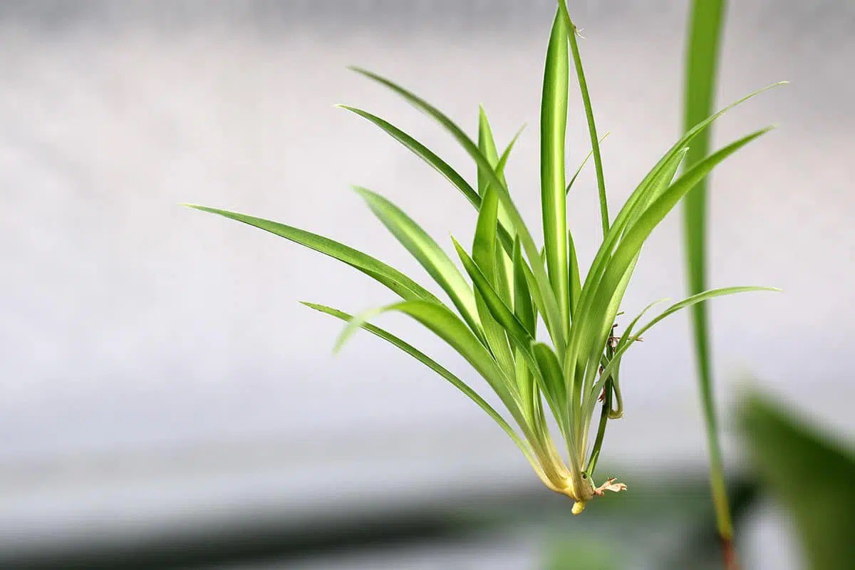
After a few weeks, one of the green lilies I bought finally started to sprout plantlets.
![]()
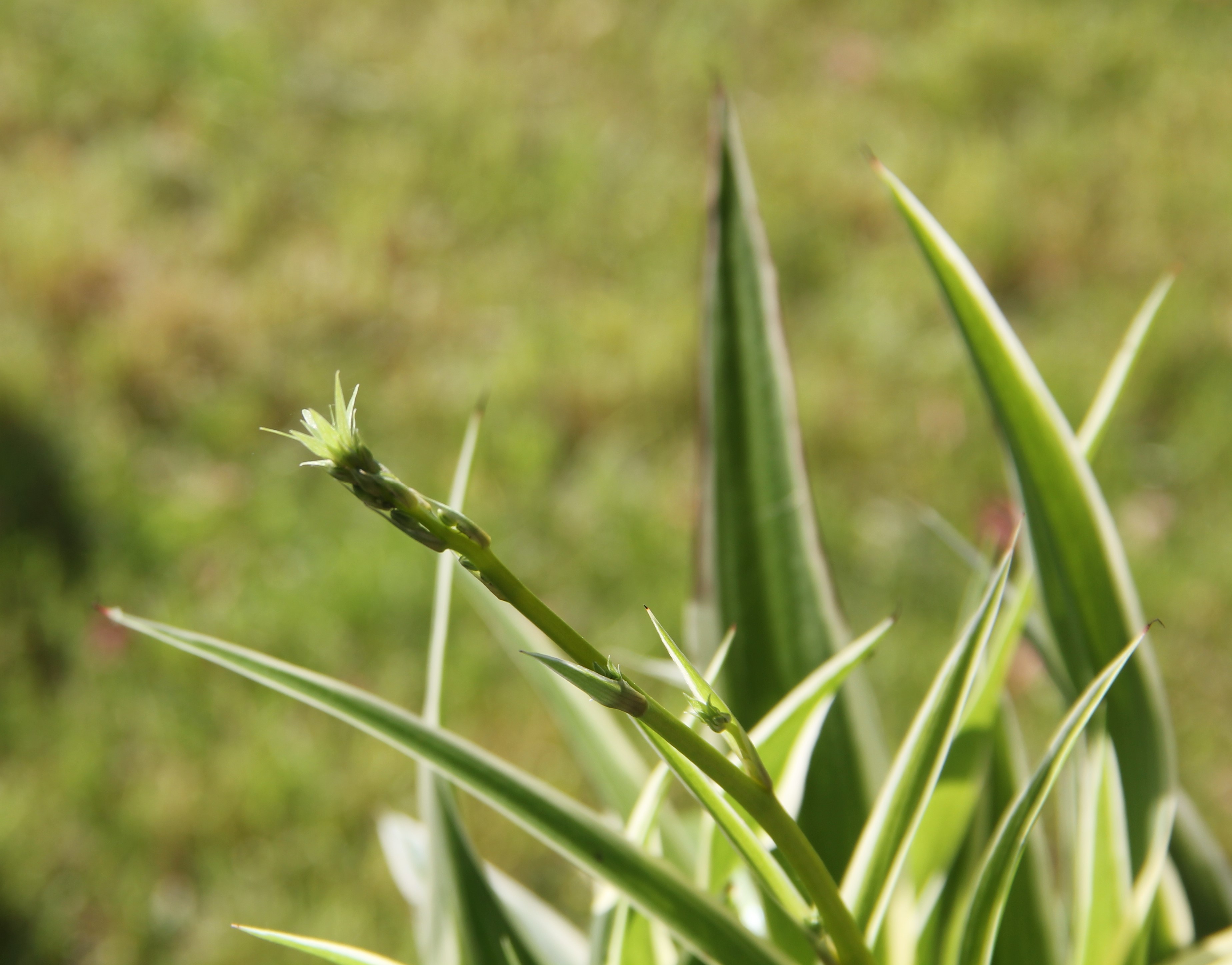
Another week later...
![]()
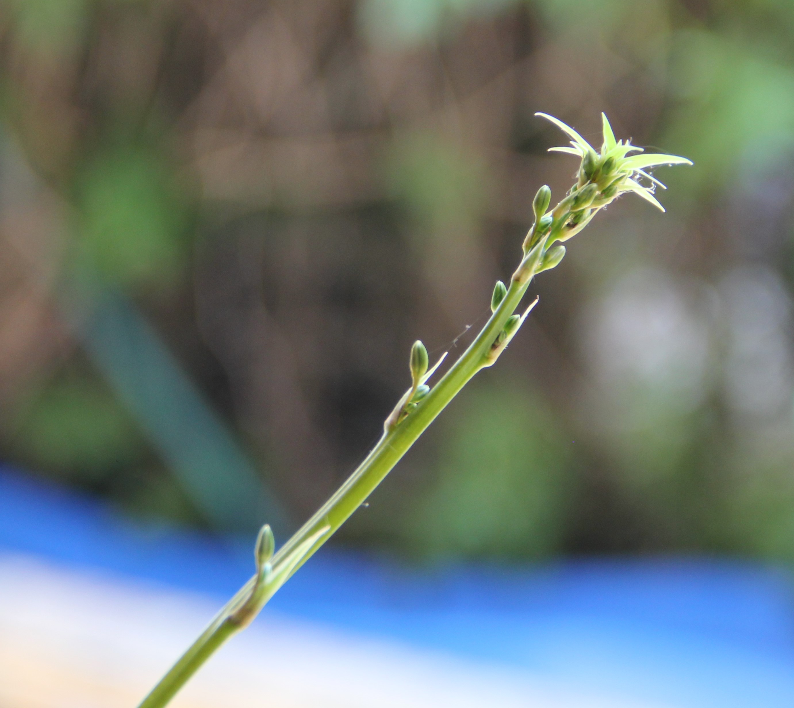
After the offshoots had at least five leaves of their own, I cut the offshoots off the flower sprout with a sharp knife and watered them to get roots.
![]()
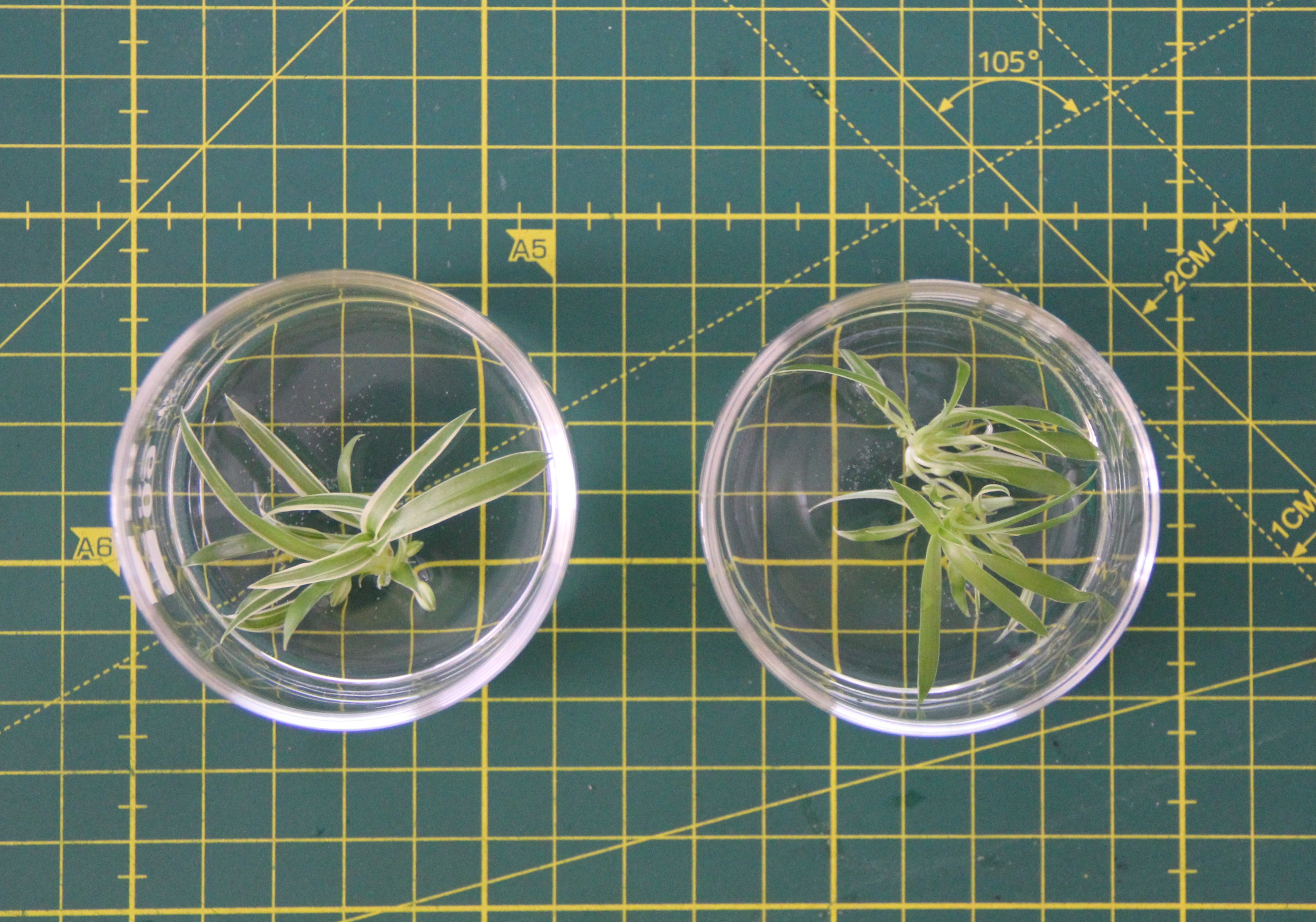
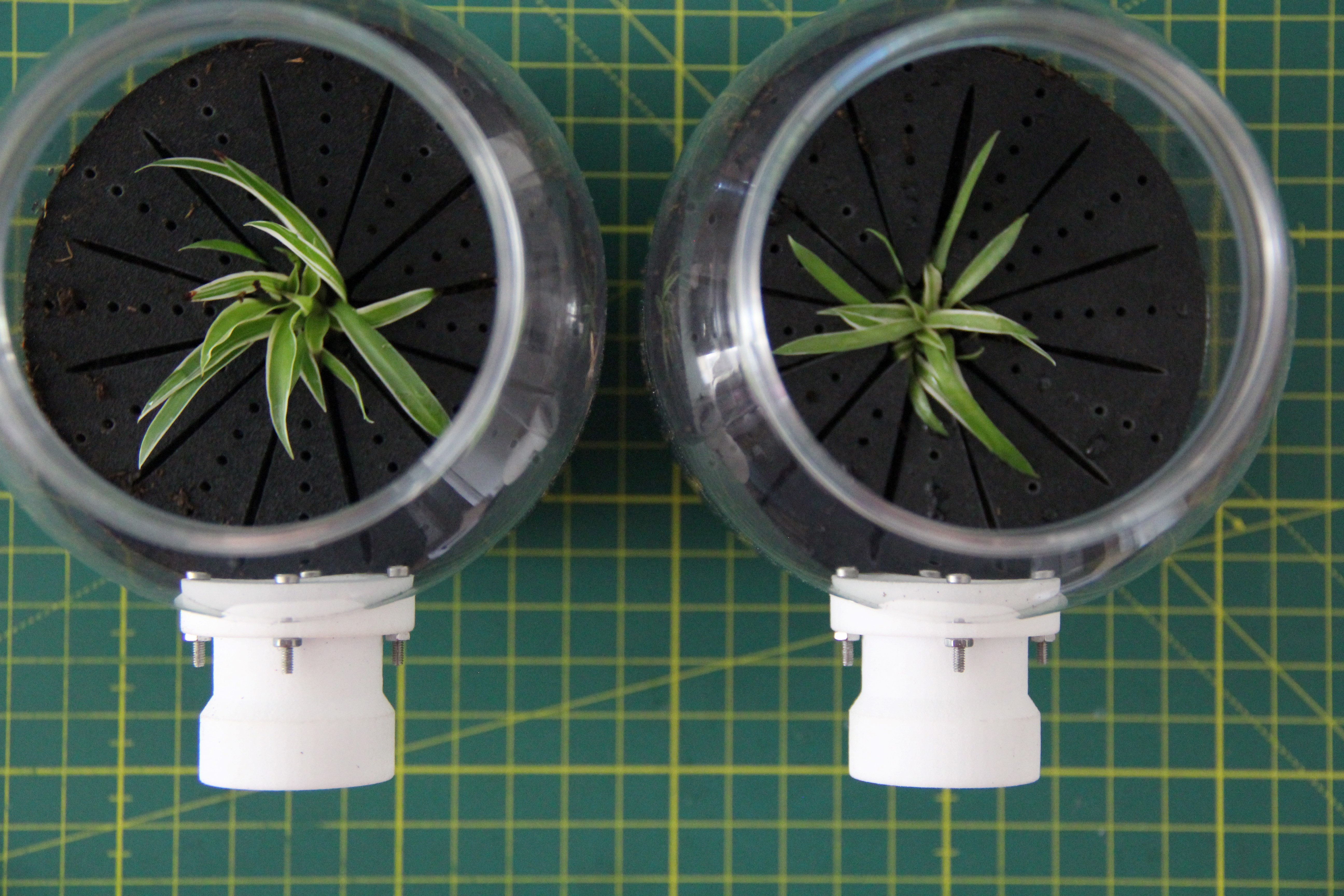
Another two weeks later, the offshoots finally got roots so I could transfer them into the plastic containers.
![]()
-
Code
04/28/2023 at 12:24 • 0 commentsThe following code displays the gas sensor values on the AR glasses.
/* Note: Because the sensor is warming up, the first 10-20 readings will always be TVOC 0 ppb and eCO2 400 ppm. */ #include <Arduino.h> #include <U8x8lib.h> #include <Wire.h> #include "Adafruit_SGP30.h" Adafruit_SGP30 sgp1; // Define two classes Adafruit_SGP30 sgp2; U8X8_SSD1306_128X64_NONAME_HW_I2C u8x8(/* reset=*/ U8X8_PIN_NONE); void setup(void) { Serial.begin(9600); u8x8.begin(); u8x8.setPowerSave(0); // Start I2C communication with the multiplexer Wire.begin(); // Init sensor on bus number 0 TCA9548A(0); sgp1.begin(); // Init sensor on bus number 7 TCA9548A(7); sgp2.begin(); } void loop(void) { printValues(sgp1, 0); printValues(sgp2, 7); } // Function to select I2C BUS void TCA9548A(uint8_t bus) { Wire.beginTransmission(0x70); // TCA9548A address Wire.write(1 << bus); // Send byte to select bus number Wire.endTransmission(); } // Function to display sensor values on the OLED void printValues(Adafruit_SGP30 sgp, int bus) { u8x8.setFont(u8x8_font_7x14B_1x2_r); TCA9548A (bus); Serial.println(bus); if(bus == 0) u8x8.drawString(2,10,"Inside: "); else u8x8.drawString(2,10,"Outside:"); u8x8.drawString(2,20,"TVOC:"); sgp.IAQmeasure(); u8x8.setCursor(2,30); u8x8.print(sgp.TVOC); u8x8.print(" ppb"); delay(3000); u8x8.drawString(2,20,"eCO2:"); u8x8.setCursor(2,30); u8x8.print(sgp.eCO2); u8x8.print(" ppm"); delay(3000); } -
Building the mask
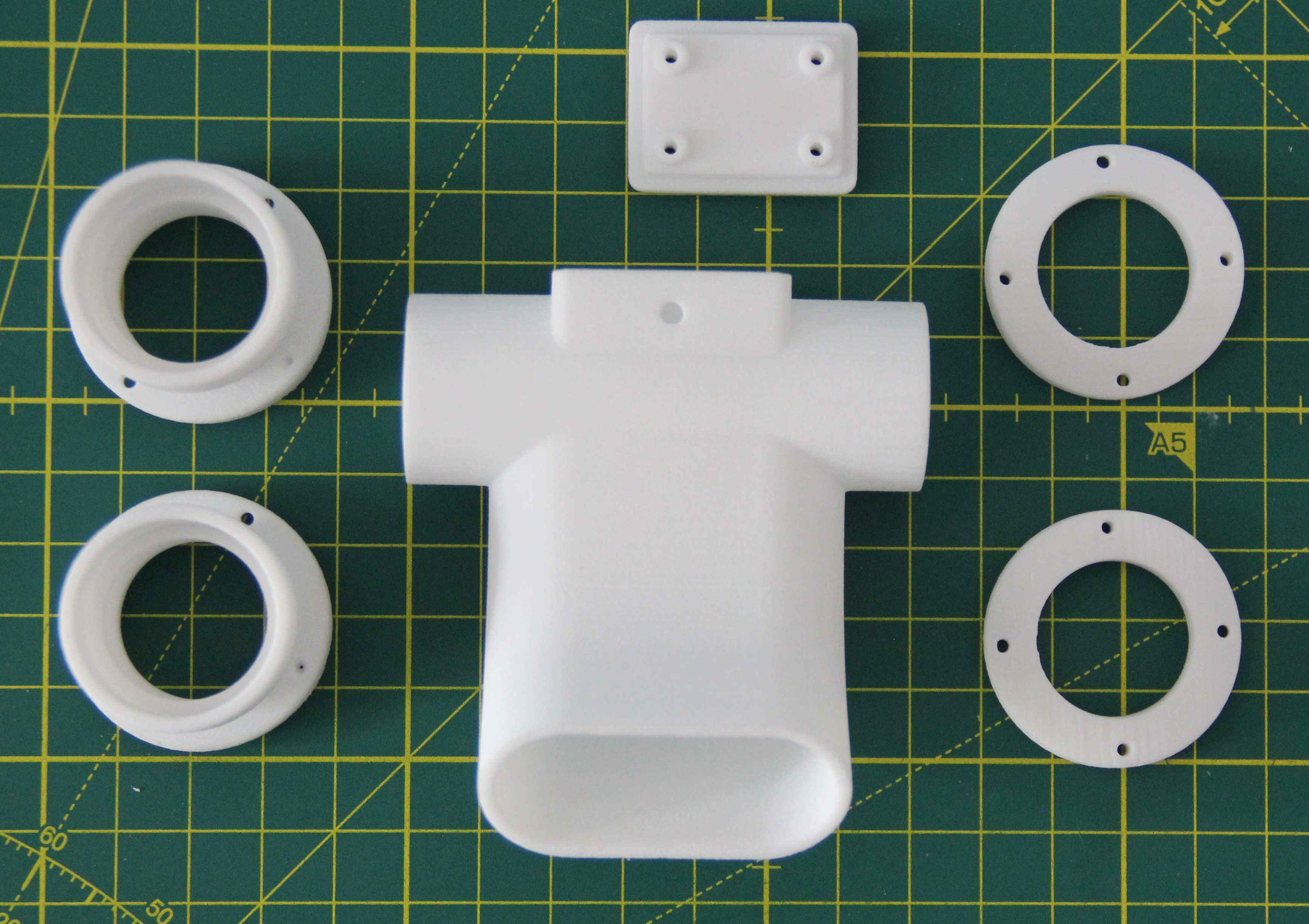
04/26/2023 at 14:56 • 0 commentsThe parts for the mask adapter have also been selective-laser-sintered in PA 12 but kept white.
![]()
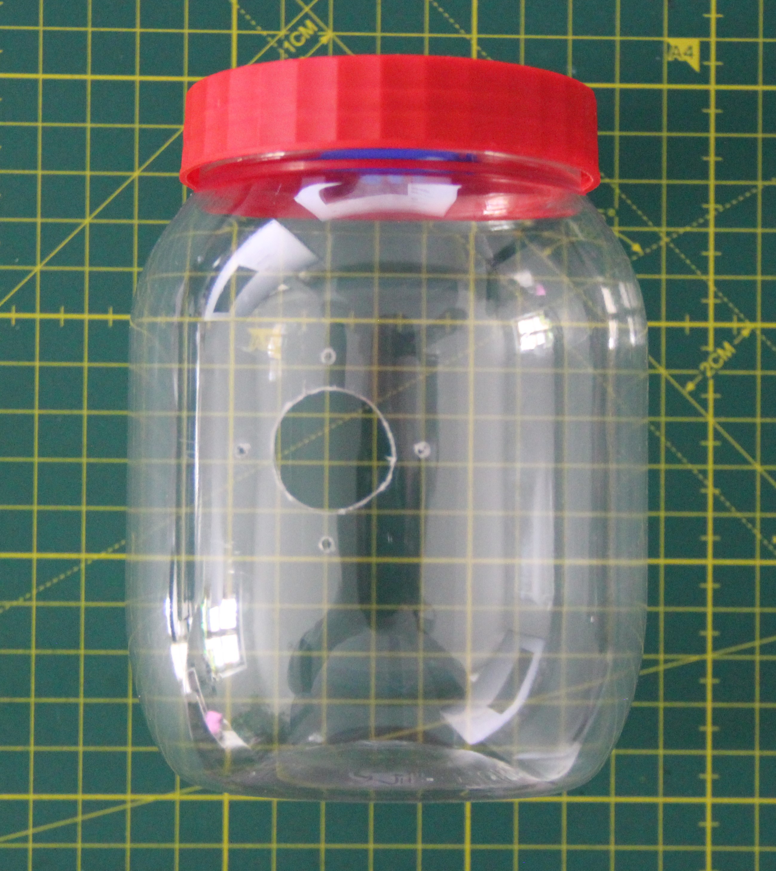
I placed valves in the lids of both containers, as described in my Log Air valves. Using a drilling template I made, I drilled the necessary holes in the containers. For the large hole, I used a step drill. The drill holes must be made at low speed, otherwise, the plastic will melt.
![]()
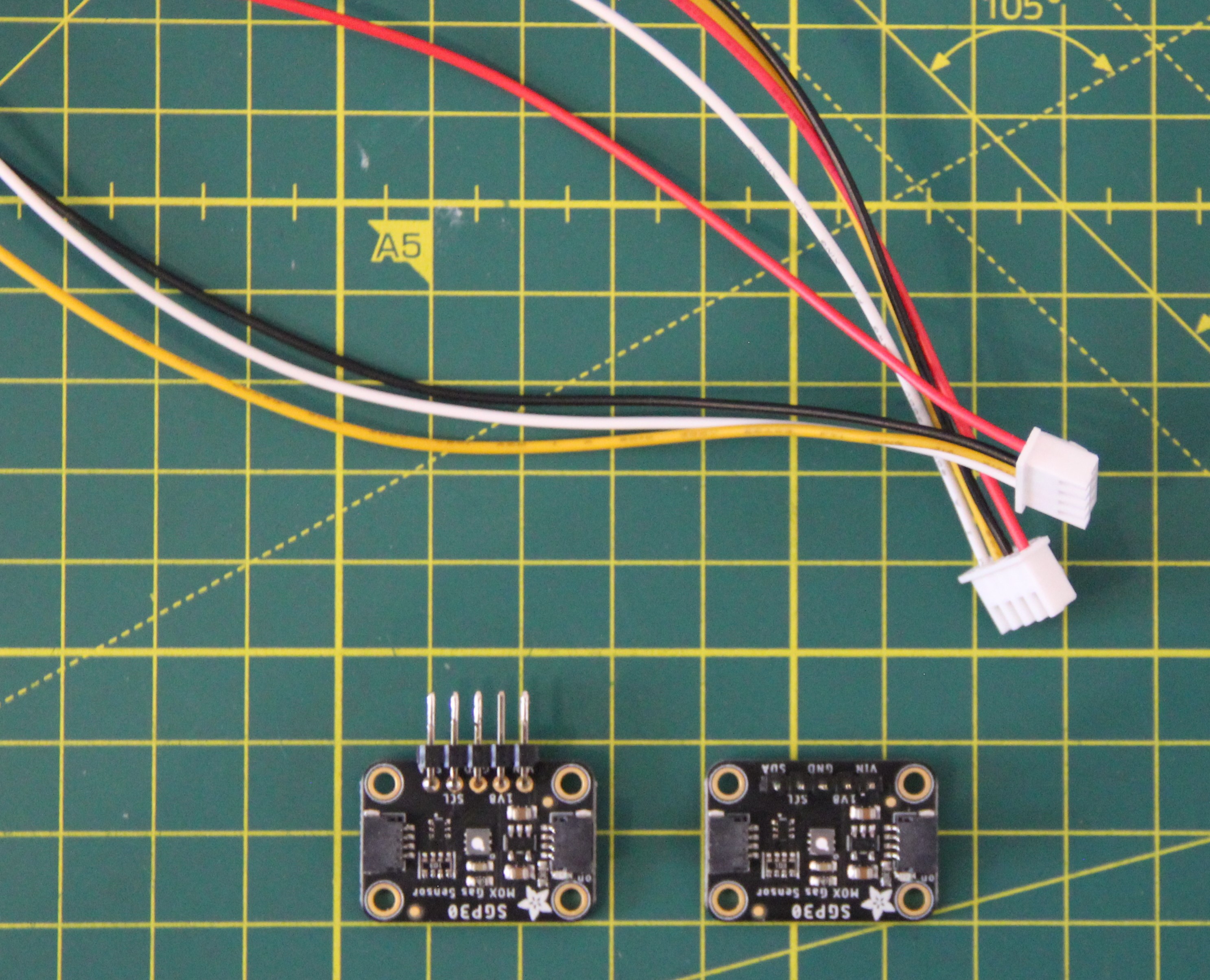
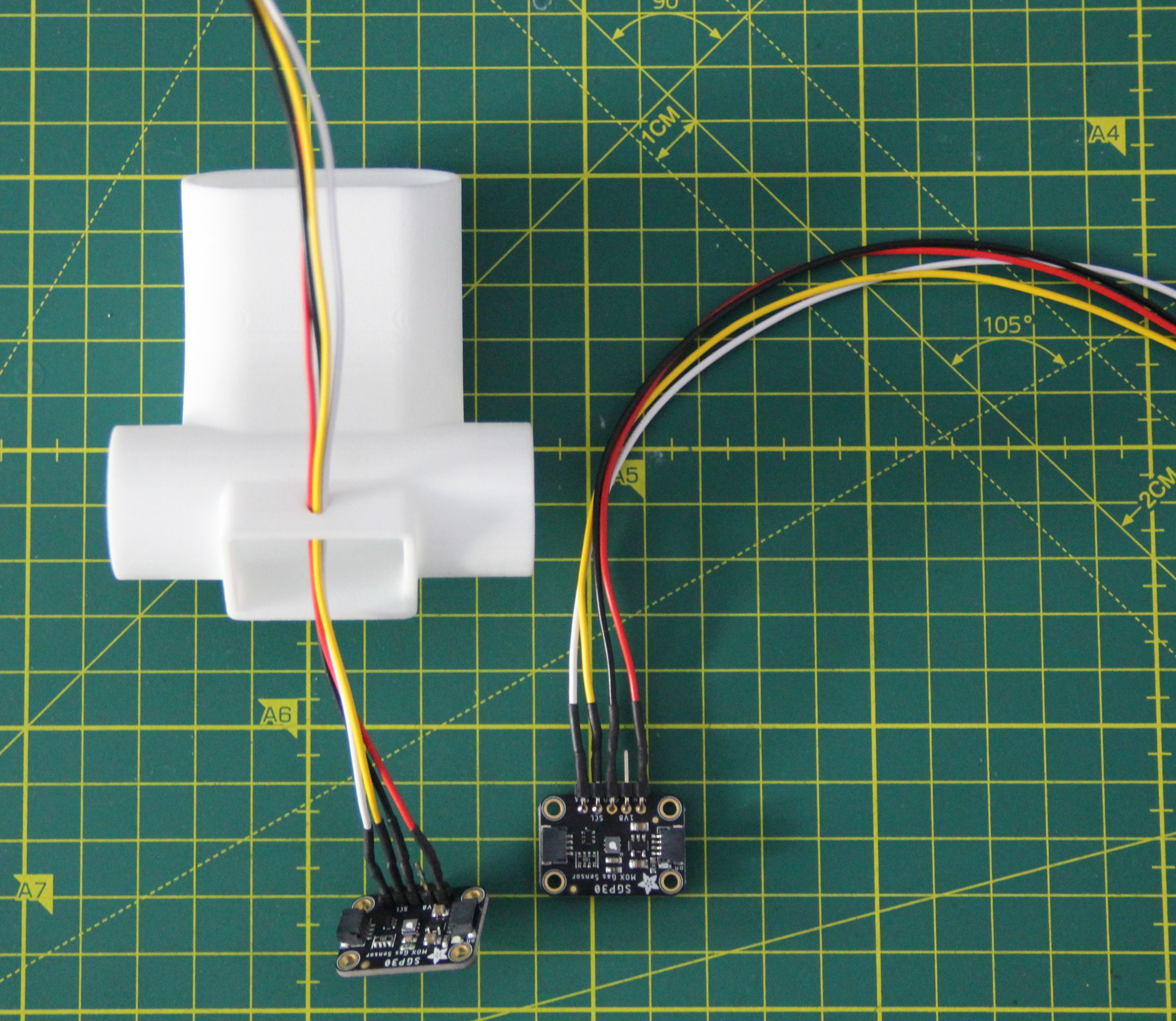
The two Adafruit SGP30 breakout boards need to have pin headers soldered into them, one straight and the other angled. Furthermore, we need two four-pin JST connectors 2.54 PH with 30 cm cable.
![]()
One wire harness was fed through the hole in the 3-D printed tee and the wires were soldered to the Adafruit SGP30 breakout board with the straight pin headers and heat shrink tubed. I did the same with the second harness and the Adafruit SGP30 breakout board with the angled pin headers.
![]()
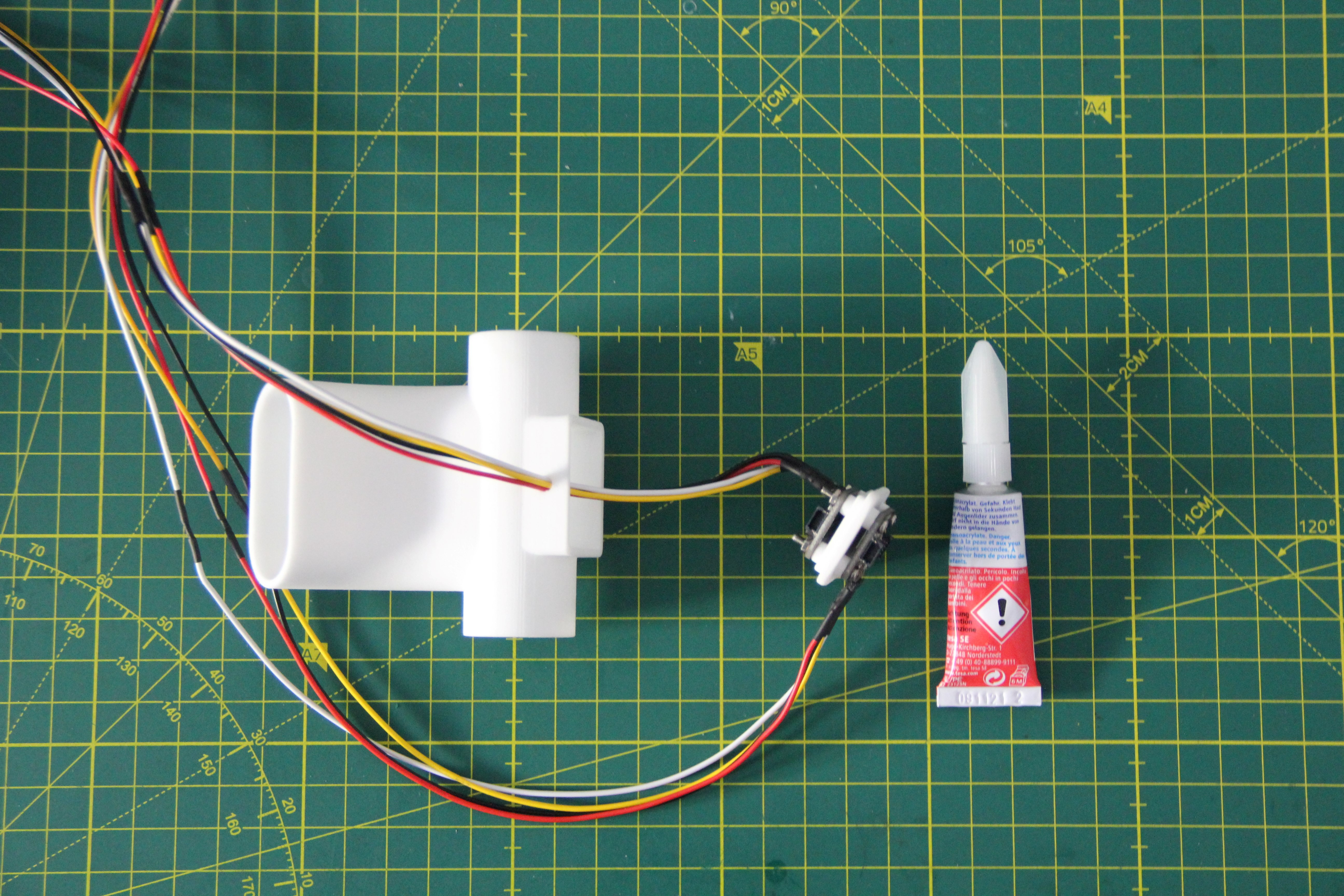
The SGP30 breakout boards were then screwed to the cover of the tee. For that, I used four stainless steel M2 x 16 mm and nuts. The four nuts were each secured with a drop of super glue. We don't want these to become loose and possibly get into our respiratory tract.
![]()
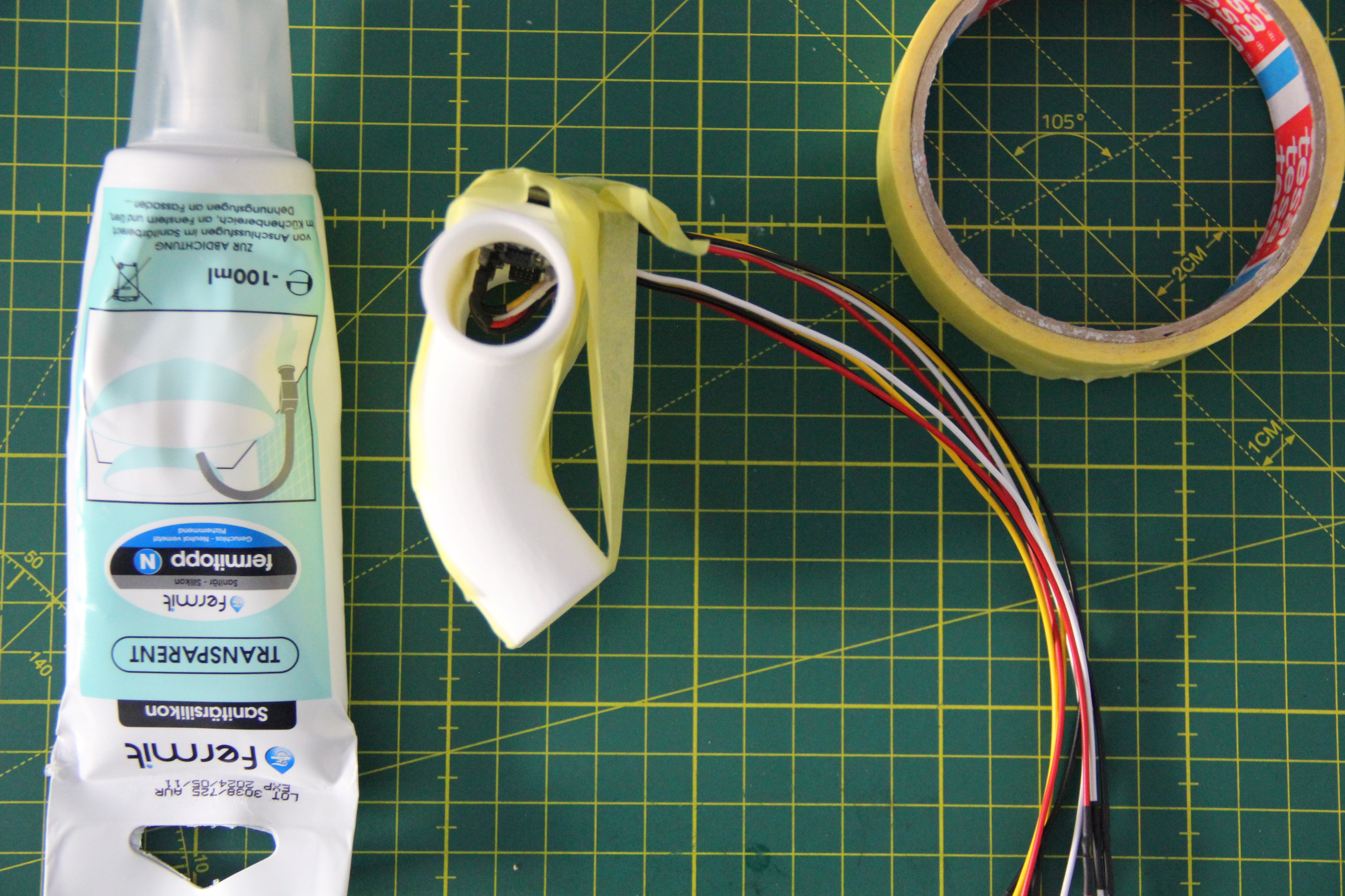
The lid was then glued into the opening of the tee with sanitary silicone. The cable gland was also sealed with silicone. Since the silicone needs 24 hours to cure, the lid was fixed with tape.
![]()
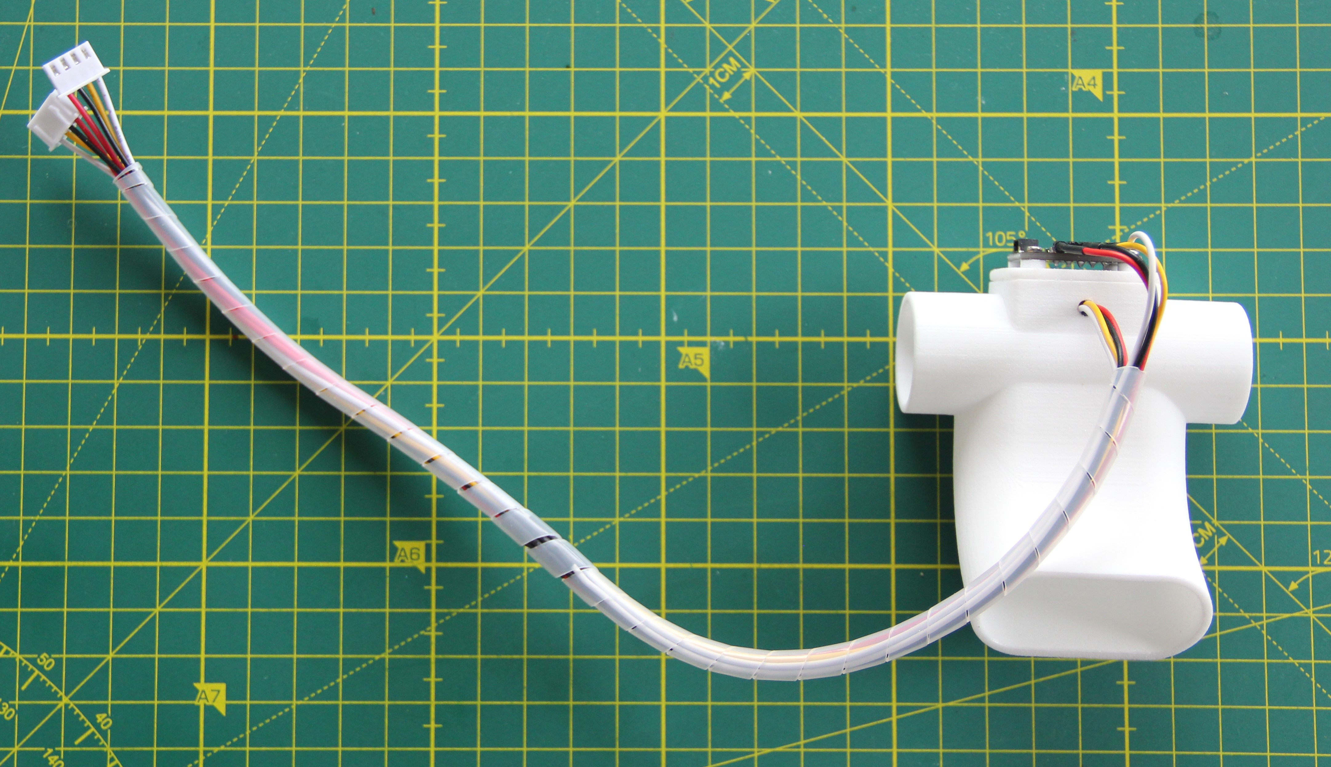
After the silicone had cured, I wrapped the two cable harnesses with spiral tubing. This looks nicer and prevents the cables from getting tangled.
![]()
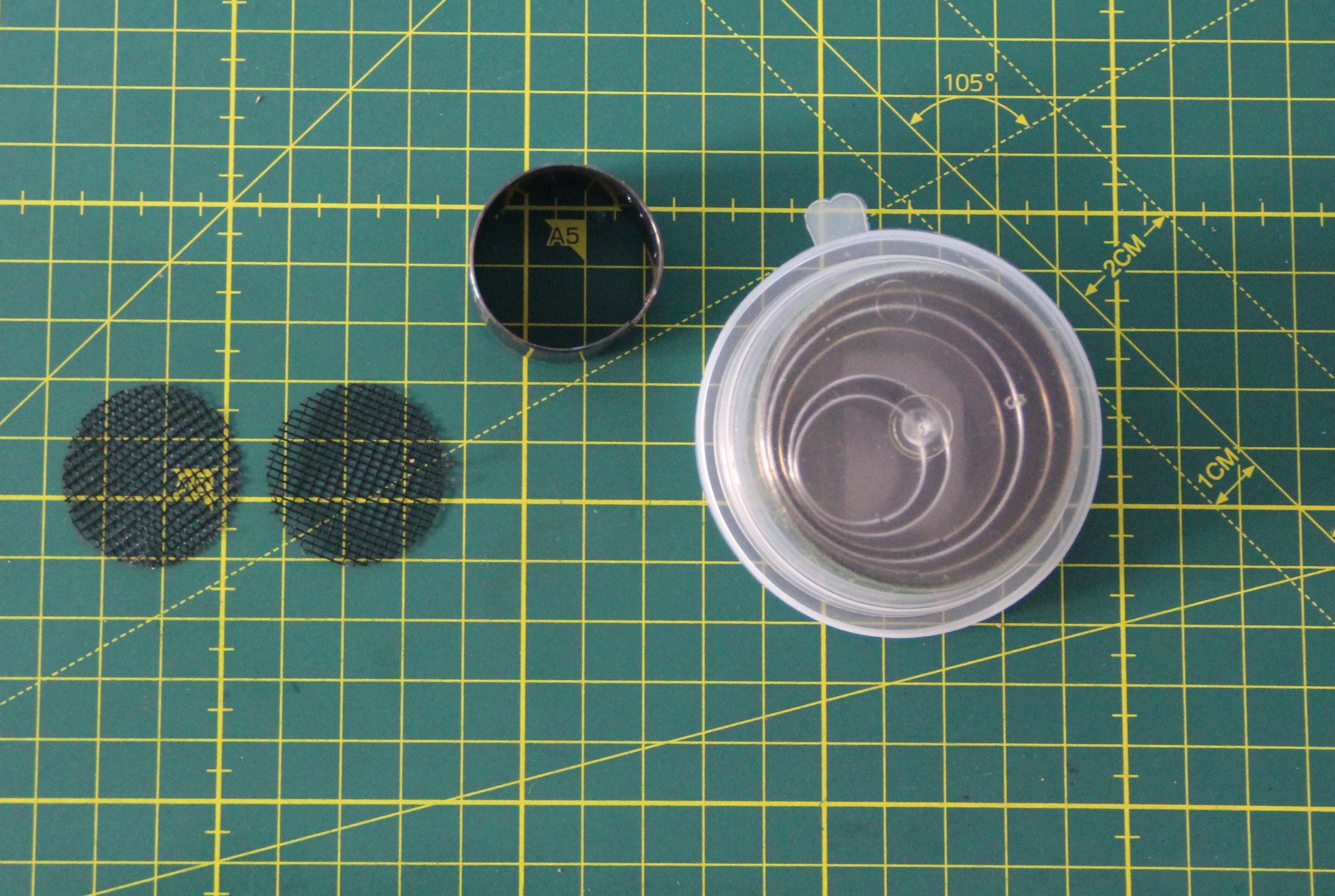
For safety reasons, I decided to install a fly screen between the inner and outer flanges. This way, nothing can accidentally get into the respiratory tract. You can also experiment with other filter materials. I punched discs out of the fly screen with a 30 mm diameter hole punch.
![]()
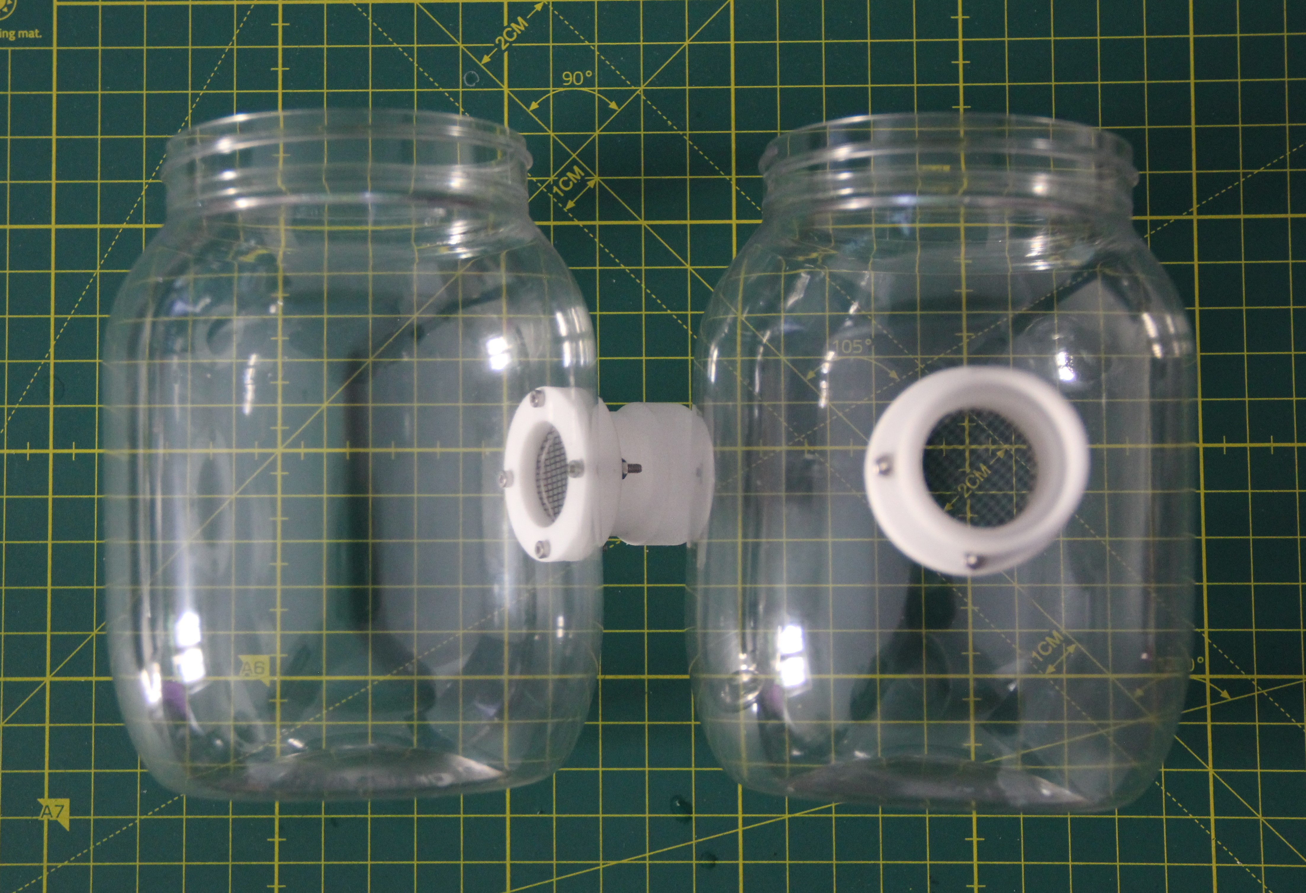
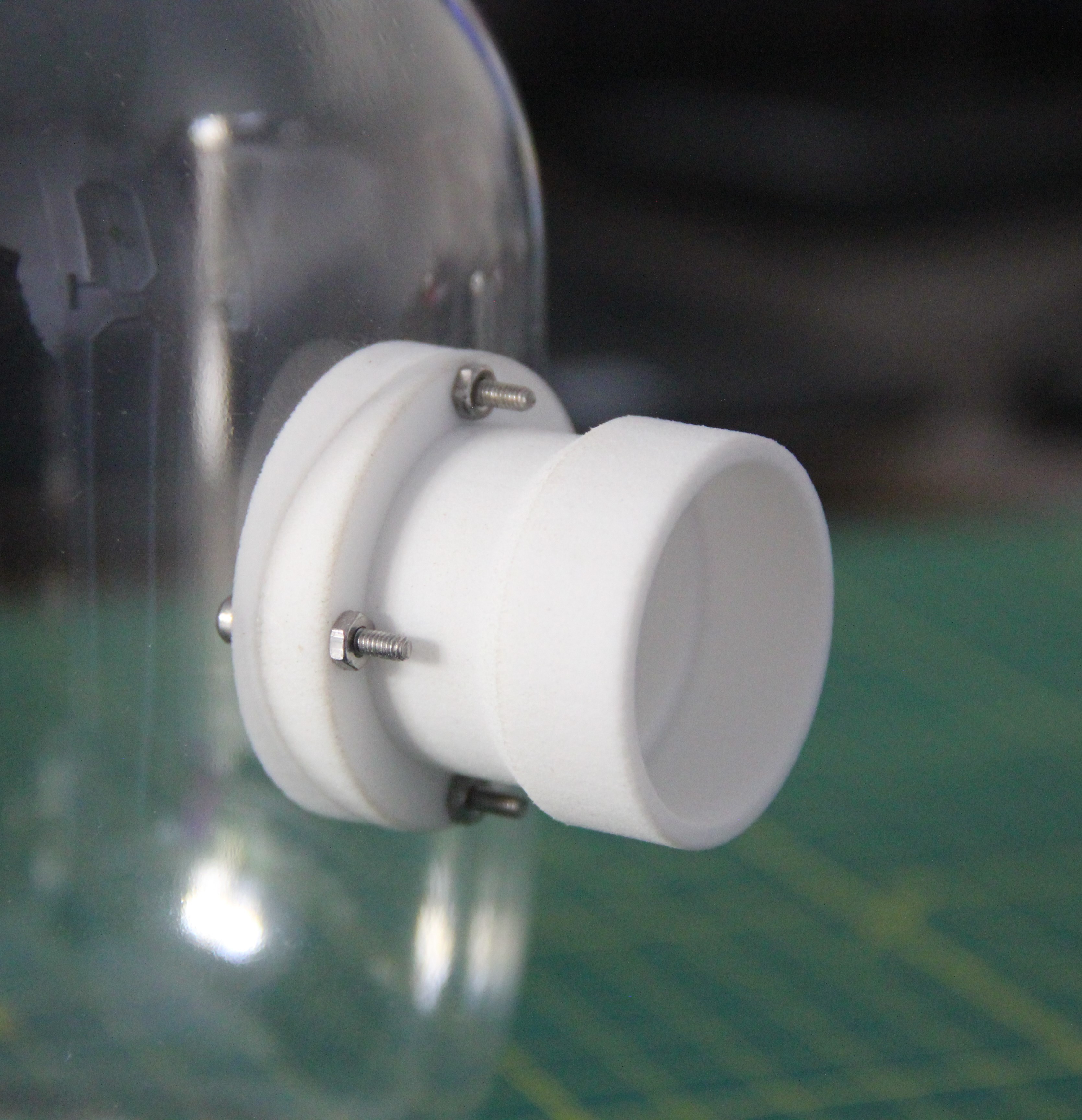
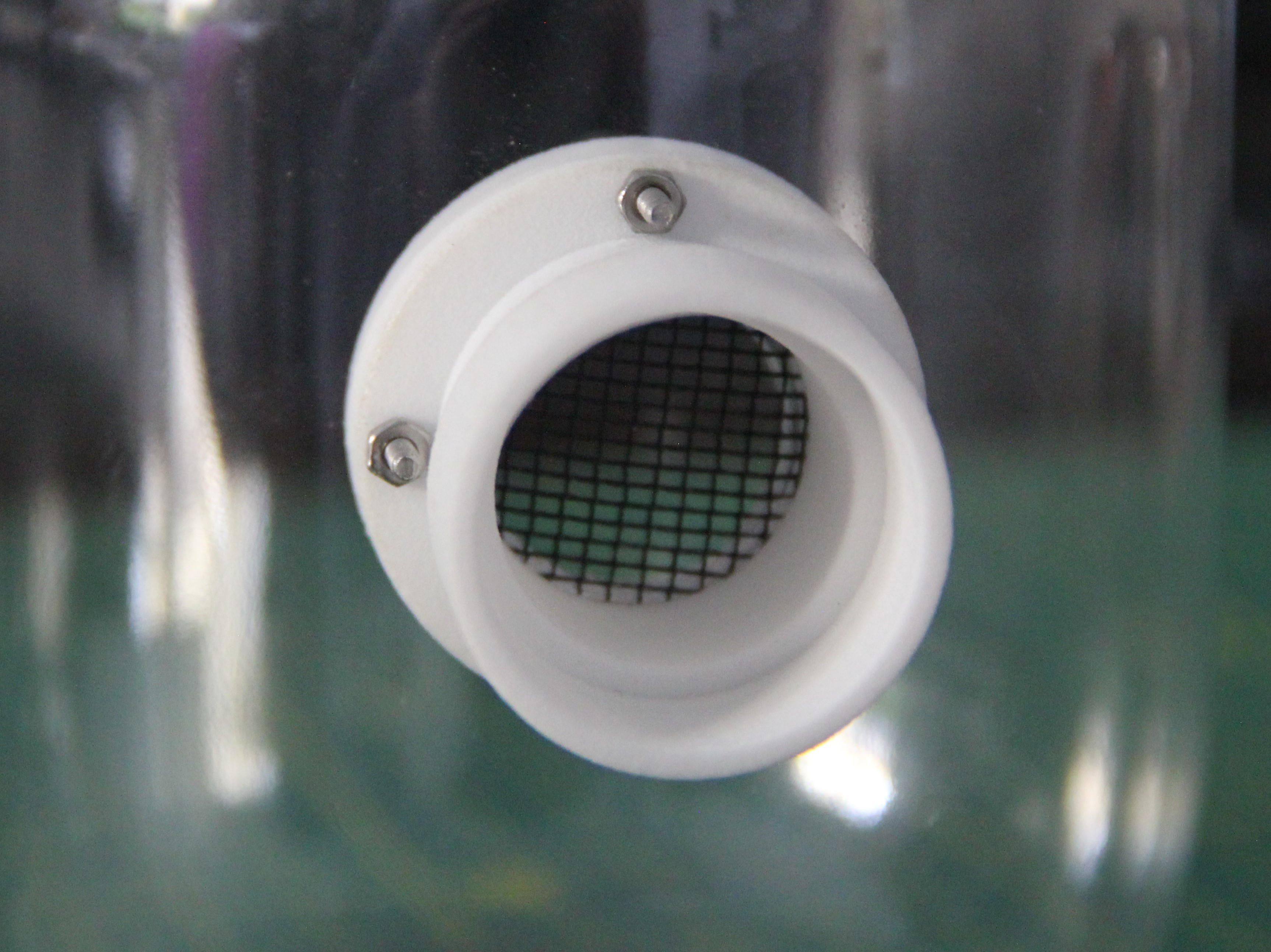
The two flanges were then bolted to the container using four M2 x 14mm stainless steel bolts and nuts each. If your hand does not fit in the opening, you can help yourself out with needle-nose pliers.
![]()
![]()
![]()
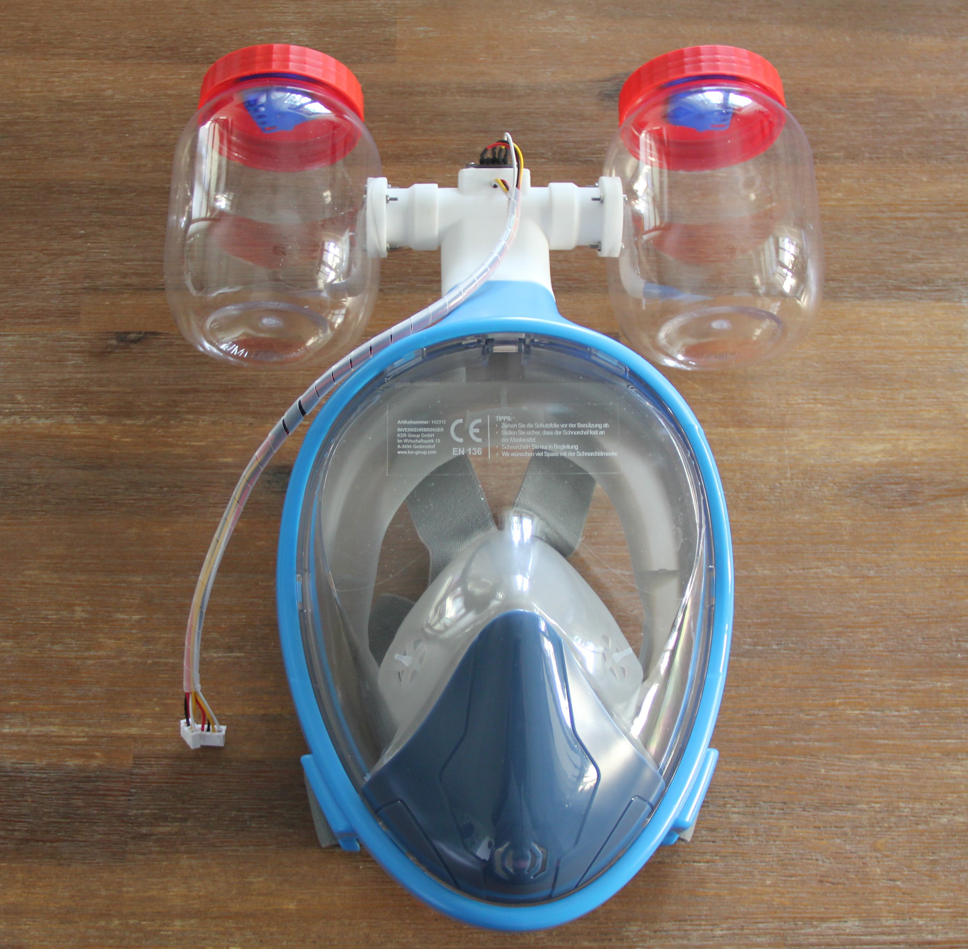
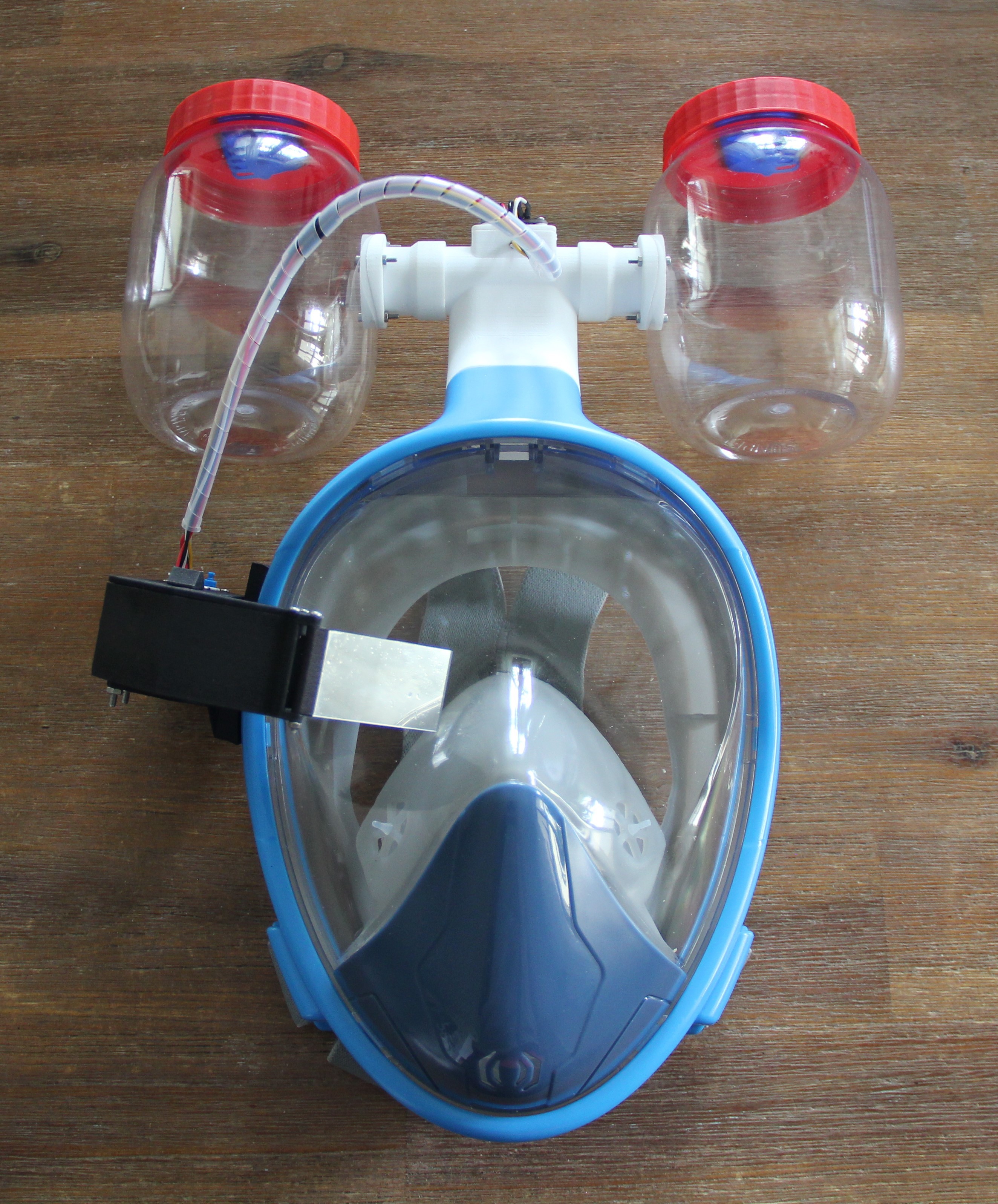
Next, I inserted the tee into the snorkel opening of the mask and then the two containers with the prepared flanges.
![]()
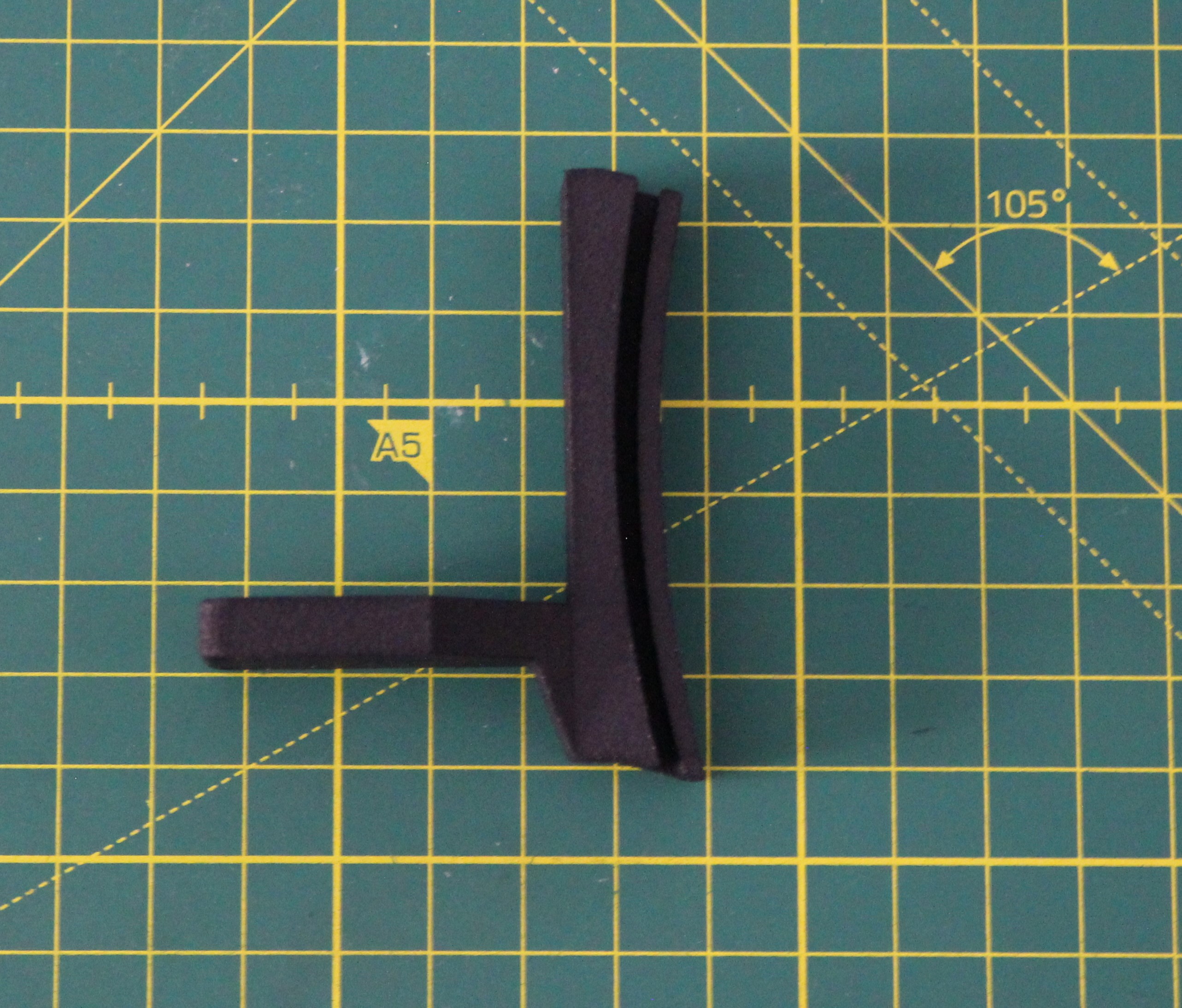
The last part that is needed is the AR glasses bracket. This part was also laser-sintered from PA 12 powder and then dyed black.
![]()
The holder is designed to be snap-fit inserted into the mask without using screws or glue, so the mask gets not damaged.
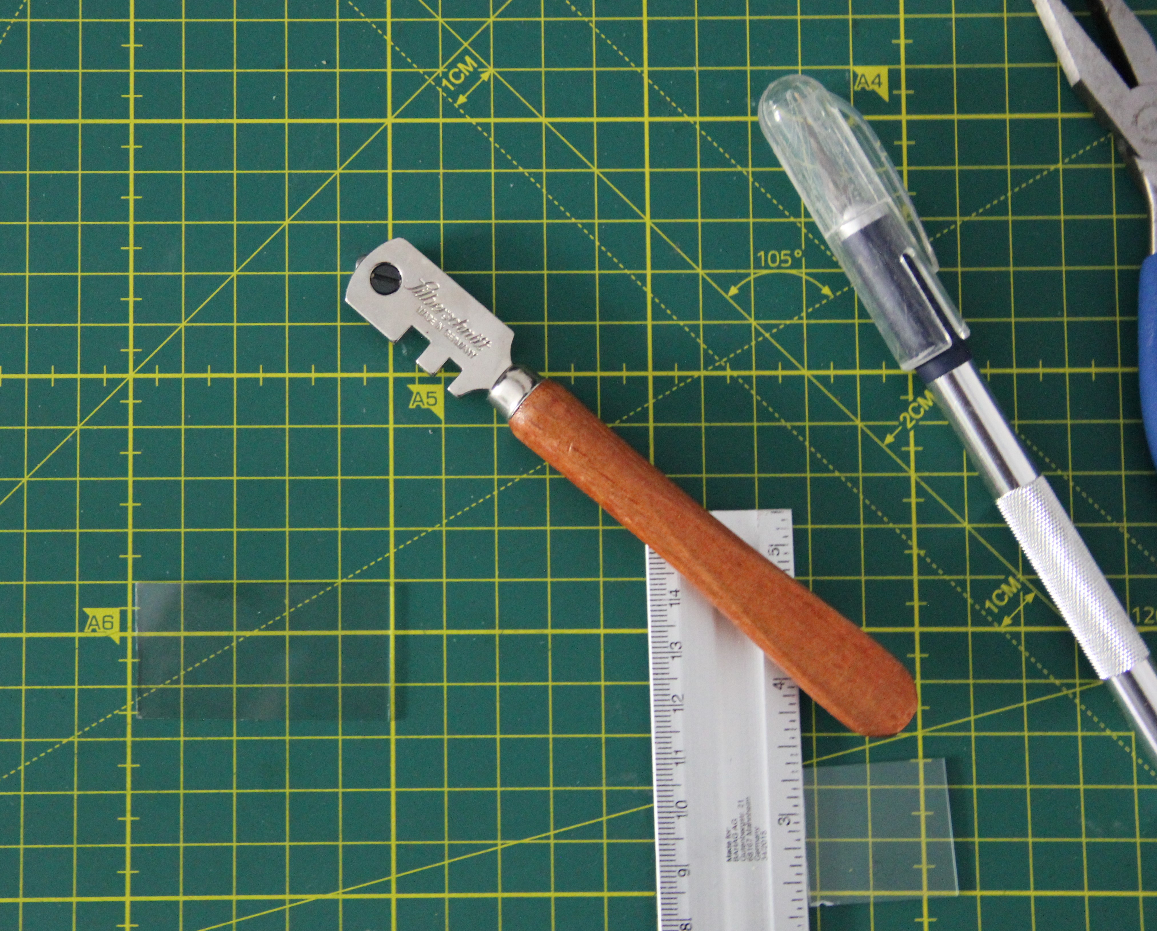
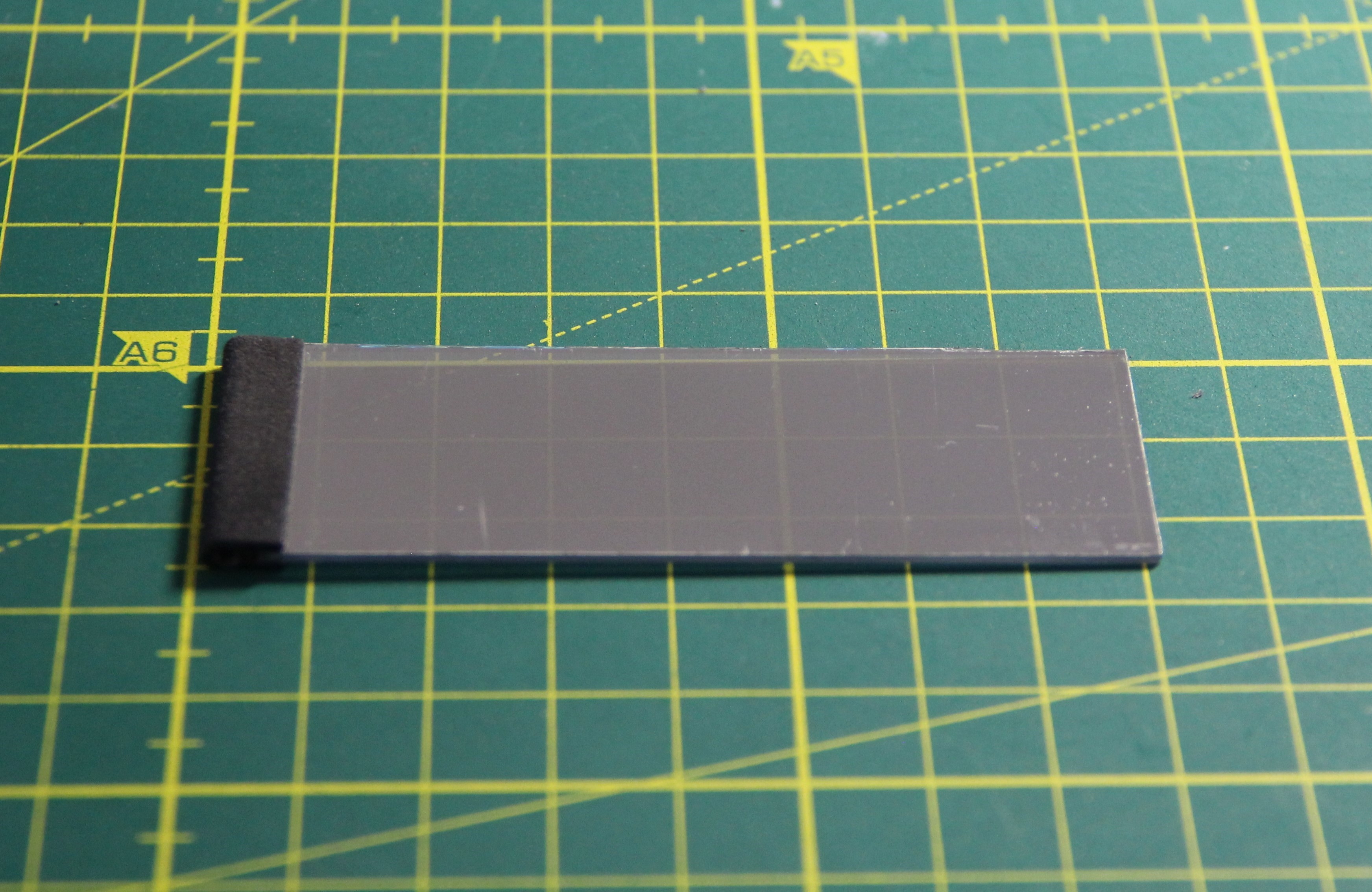
Since the microscope slide interfered with the nose section of the mask, I shortened it. This can easily be done with a glass cutter.
![]()
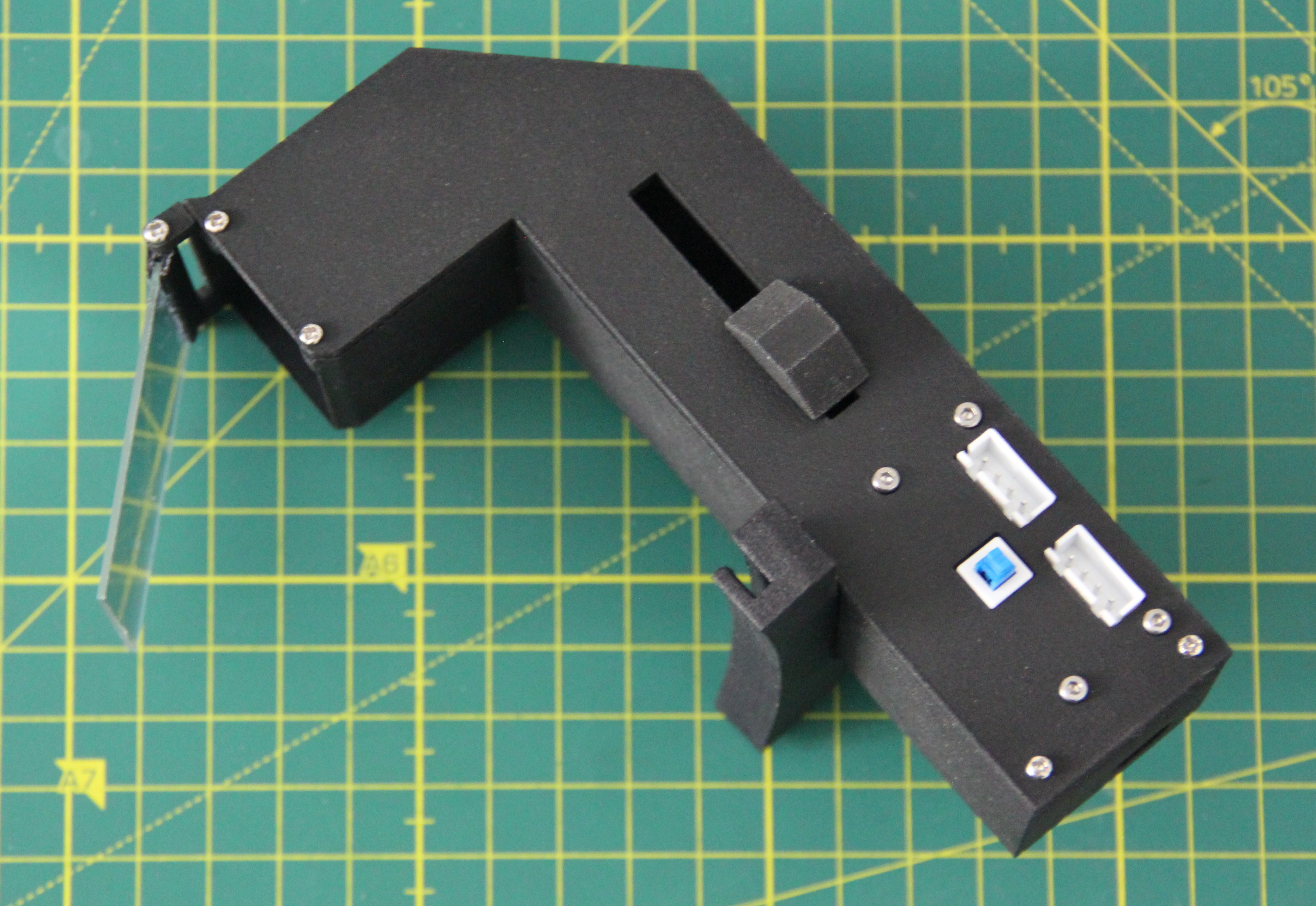
The bracket was then bolted to the AR glasses using 2 stainless steel screws 3 x 12 mm and nuts.
![]()
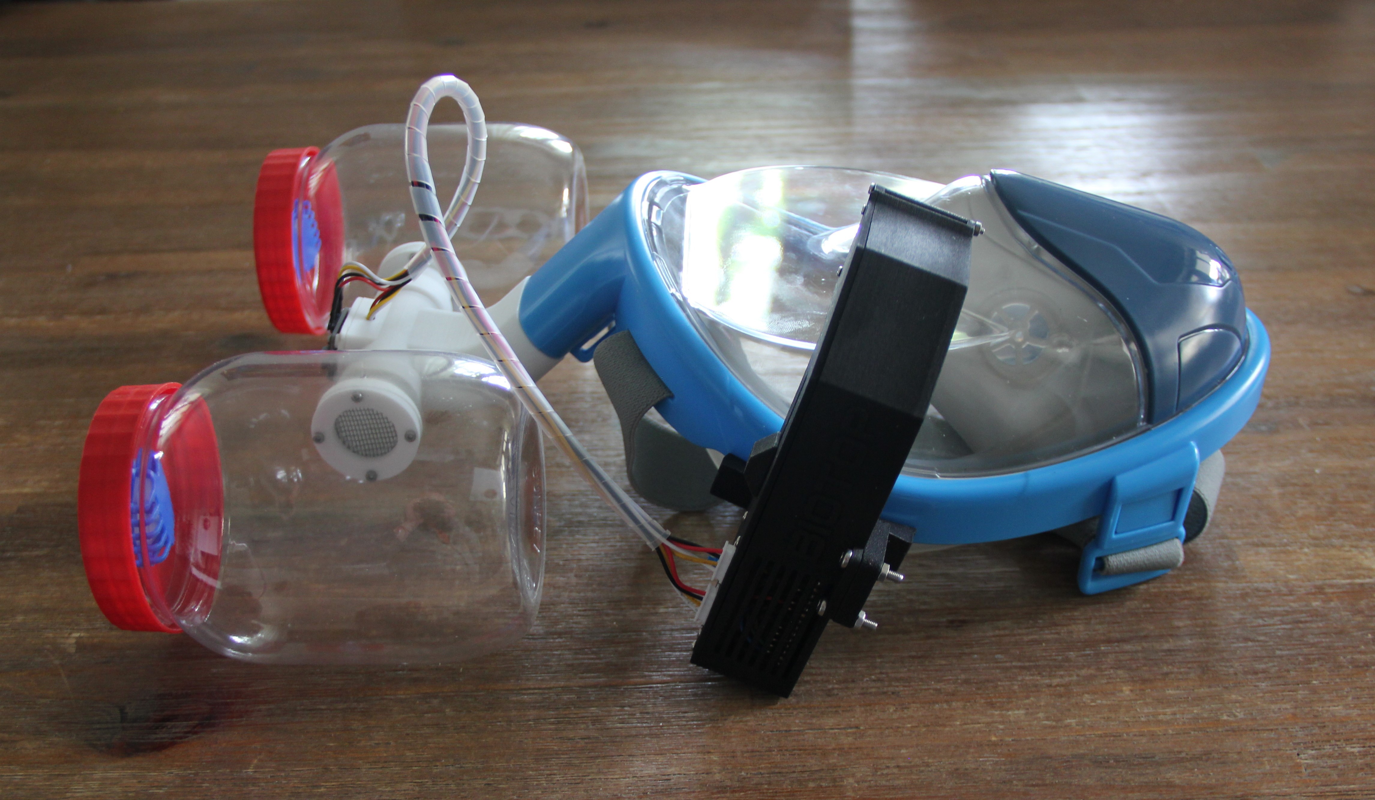
Front and side view of the finished mask:
![]()
![]()
-
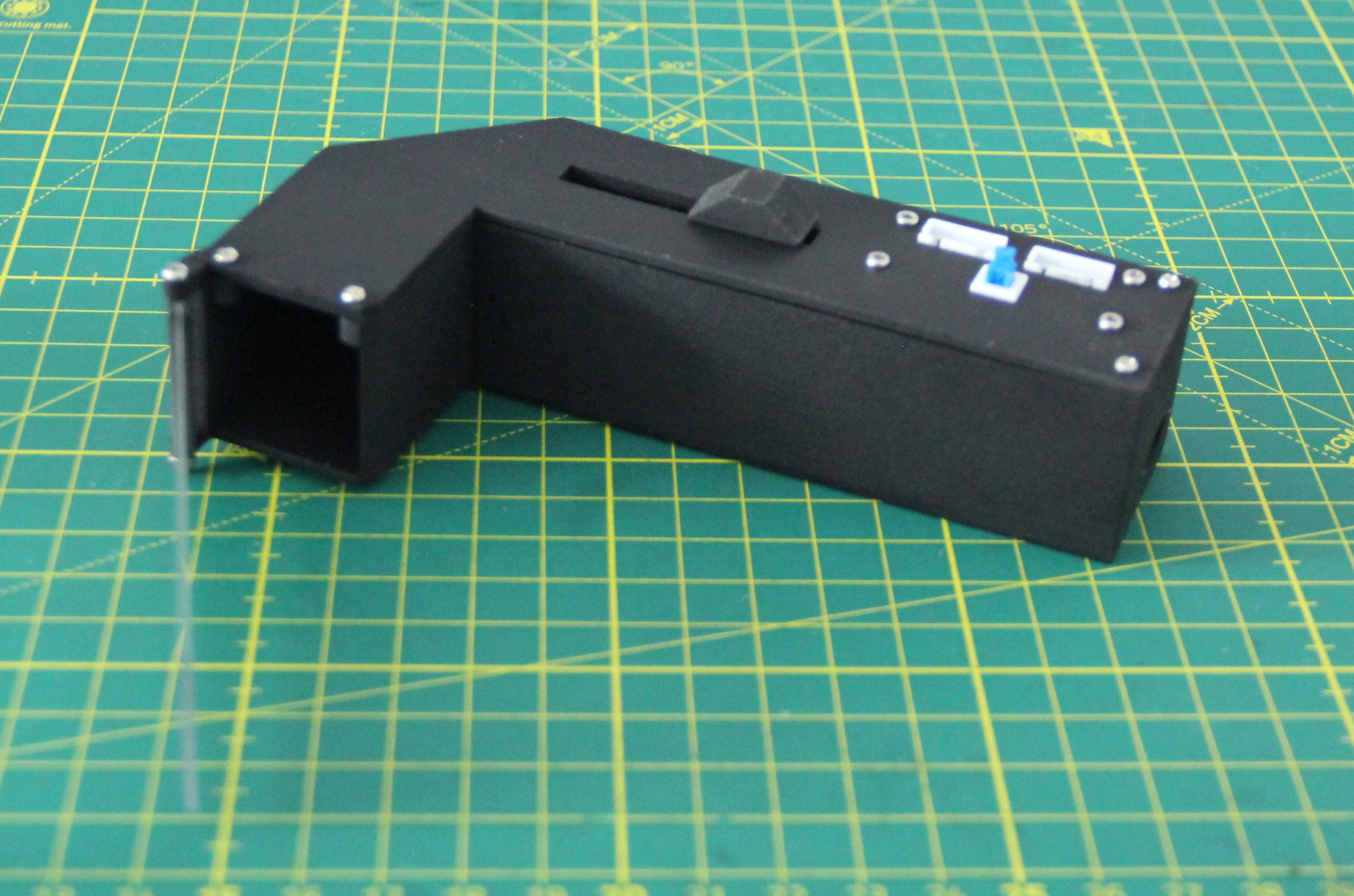
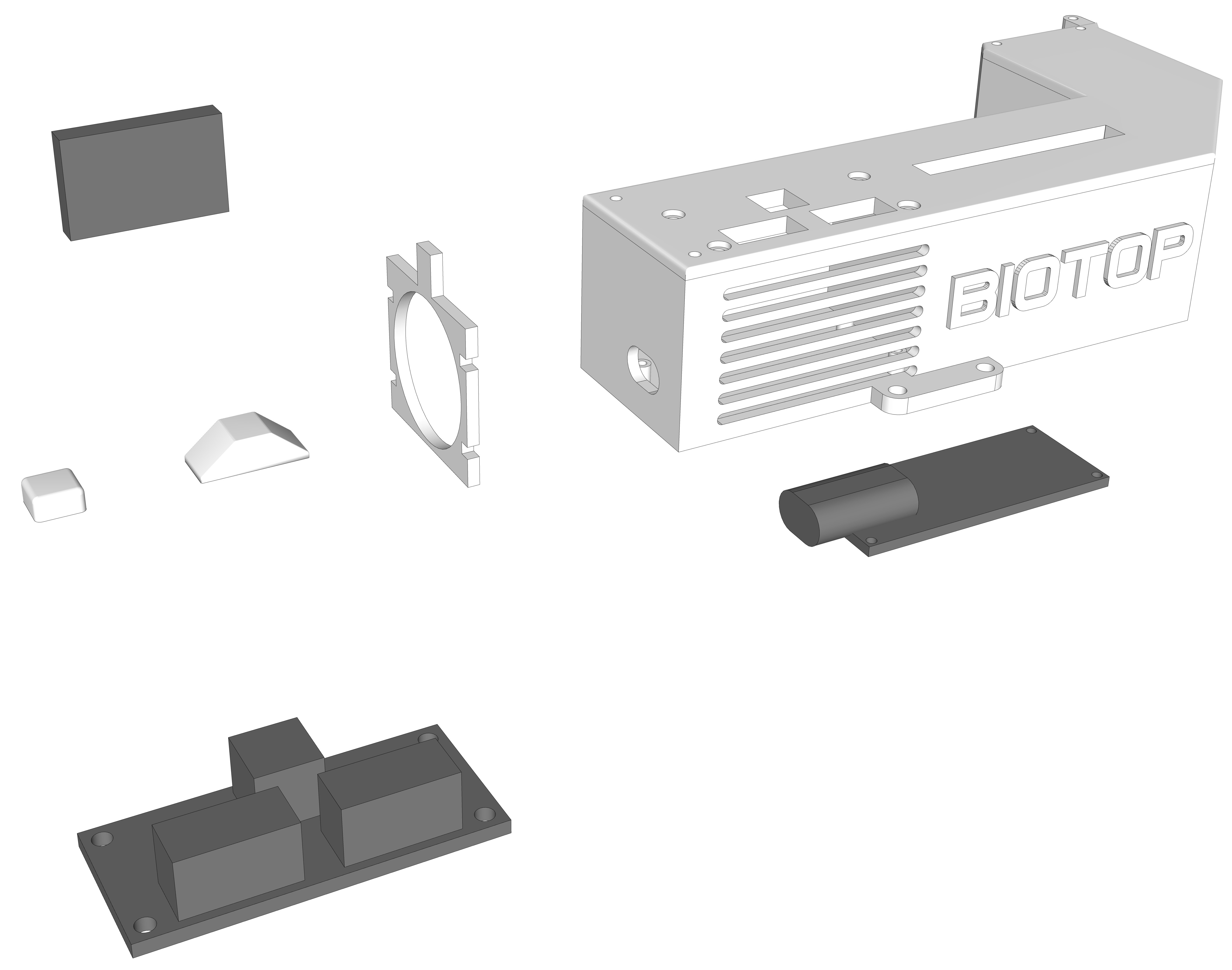
Building the AR glasses
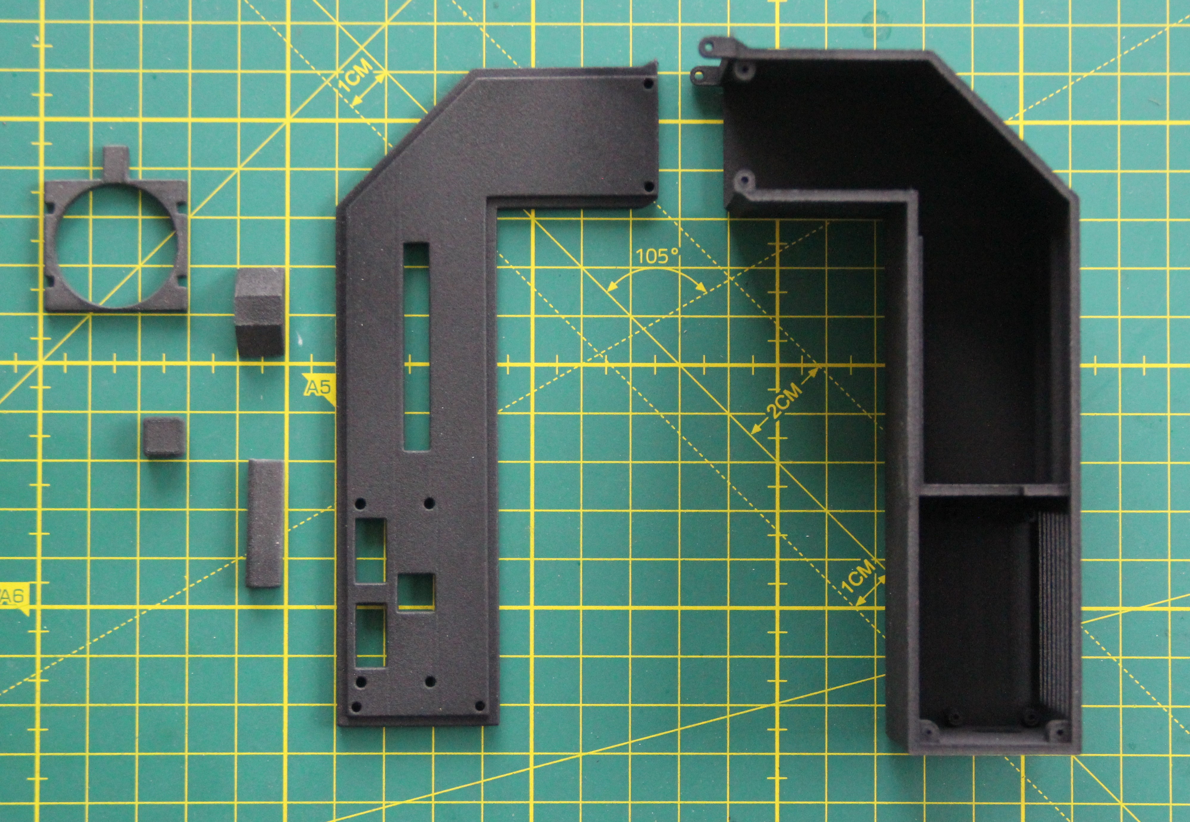
04/25/2023 at 12:39 • 0 commentsThe parts for the glasses have been selective-laser-sintered in PA 12 and then dyed black.
![]()
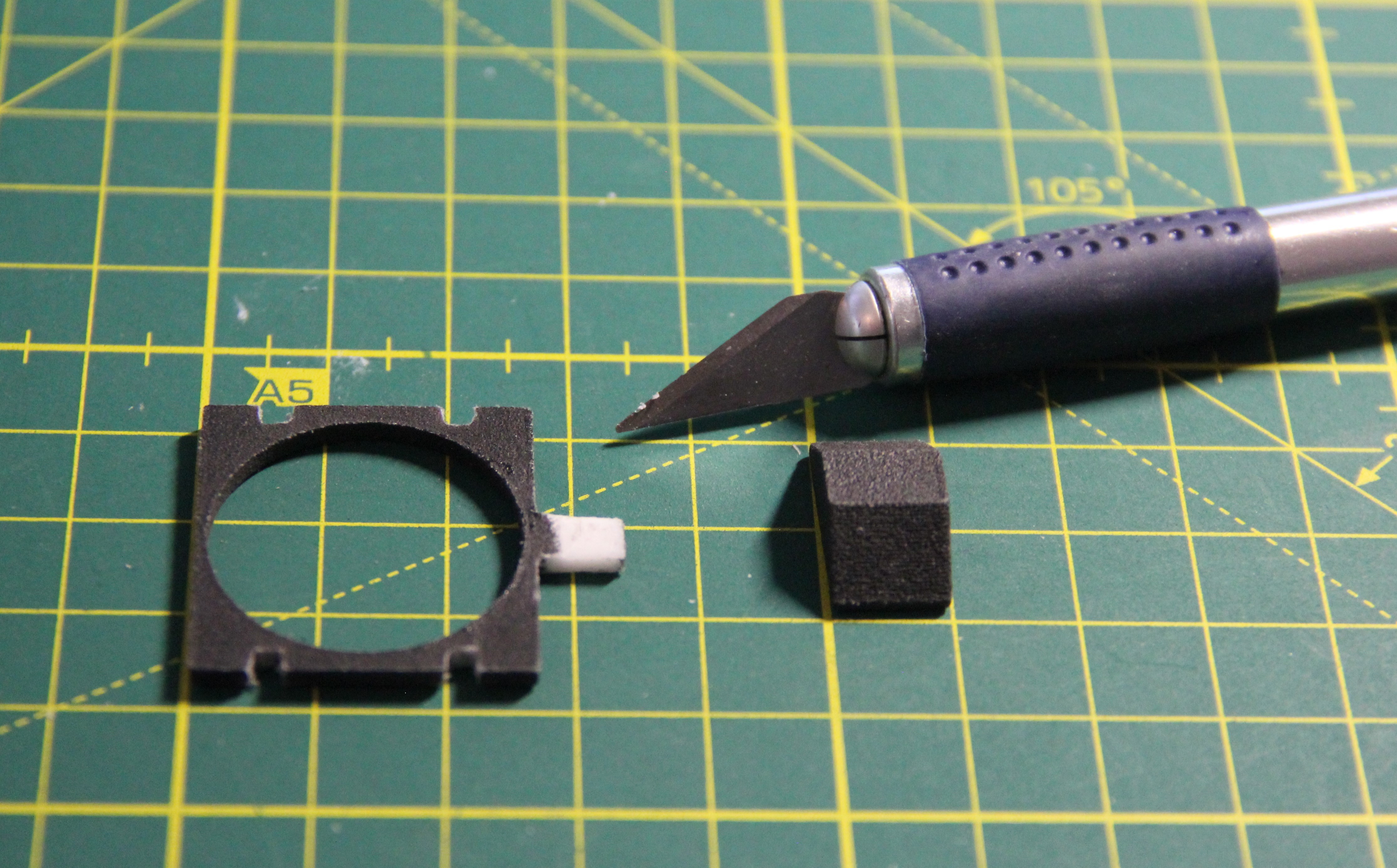
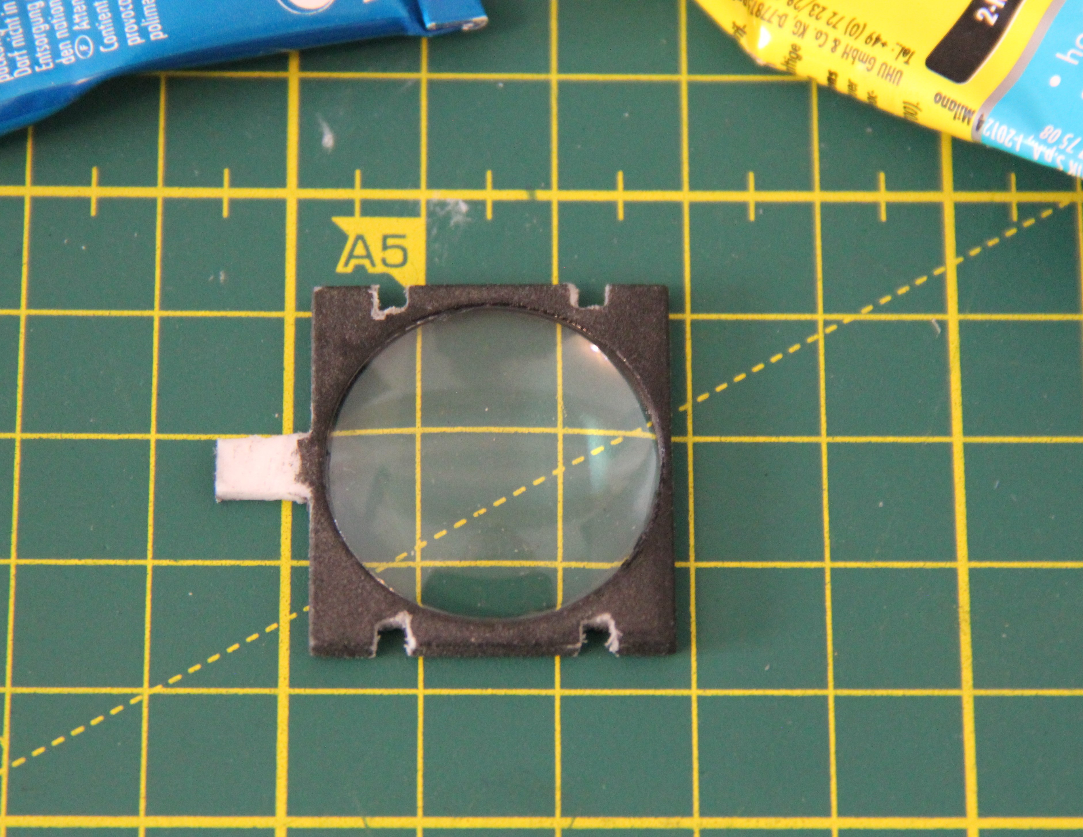
I had to trim the slots of the lens holder a bit with a cutter knife.
![]()
Then I glued the lens in place with 2-component epoxy glue.
![]()
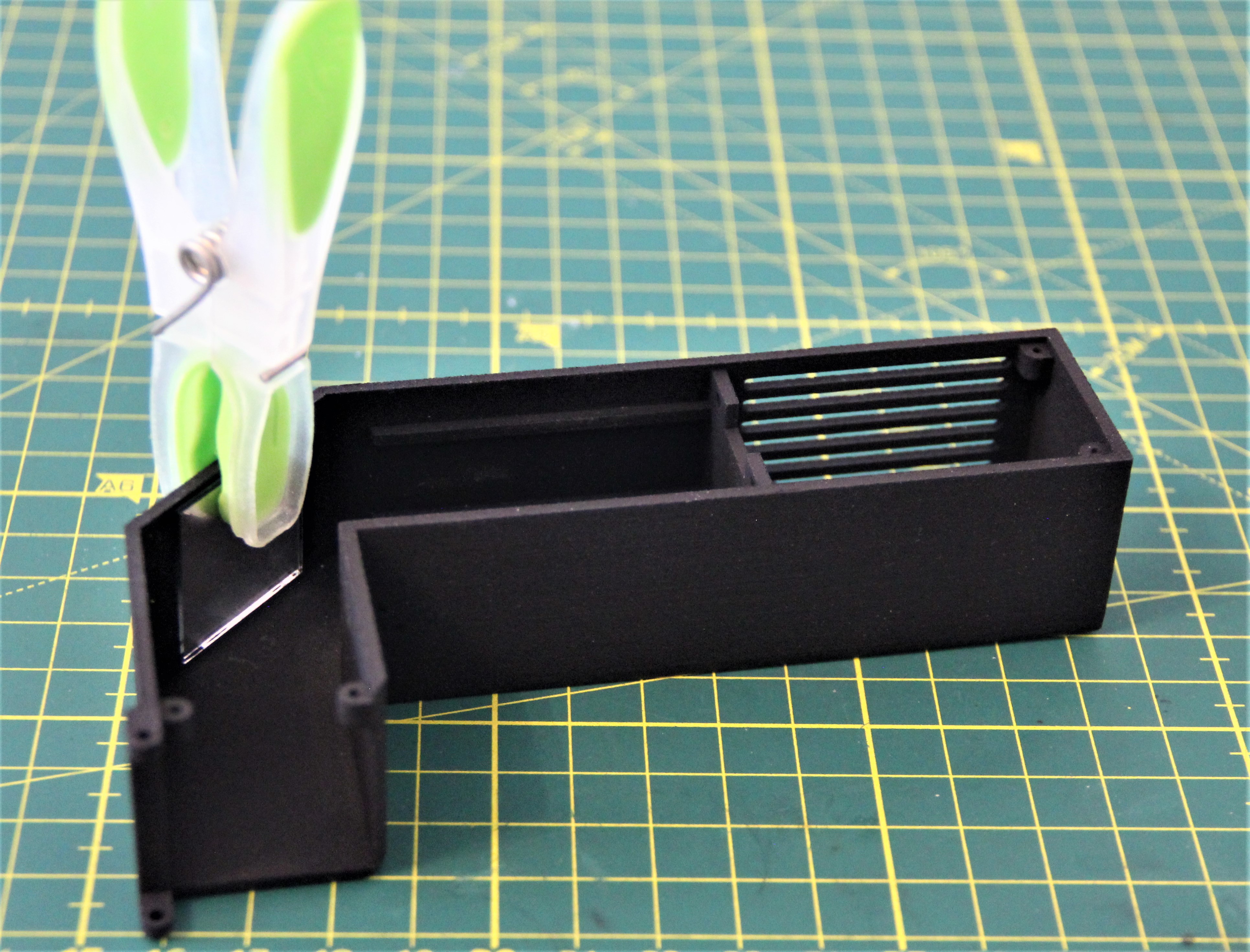
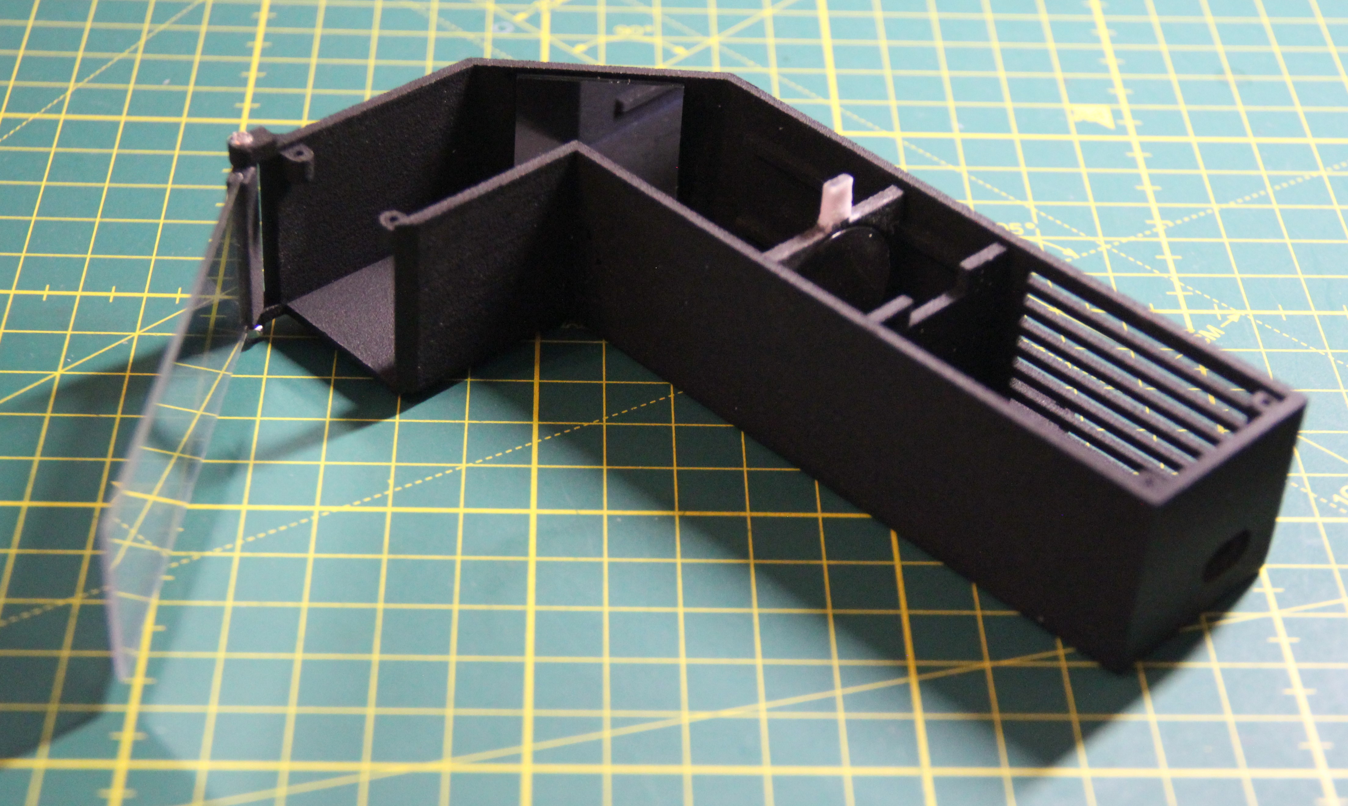
I also glued the mirror into the housing with 2-component epoxy glue. A recess is provided so that it can be positioned more easily.
![]()
Next, I covered a microscope slide with semi-mirrored foil. Care must be taken so that no bubbles form. Then I inserted the slide into the appropriate 3-D printed holder and secured it with two drops of super glue.
![]()
Using an M2 x 35mm bolt and nut, I then attached the microscope slide to the housing. The mirror foil should be on the side facing the eye. It should be not too easy to pivot the microscope slide. The M2 nut was finally secured with a drop of super glue.
![]()
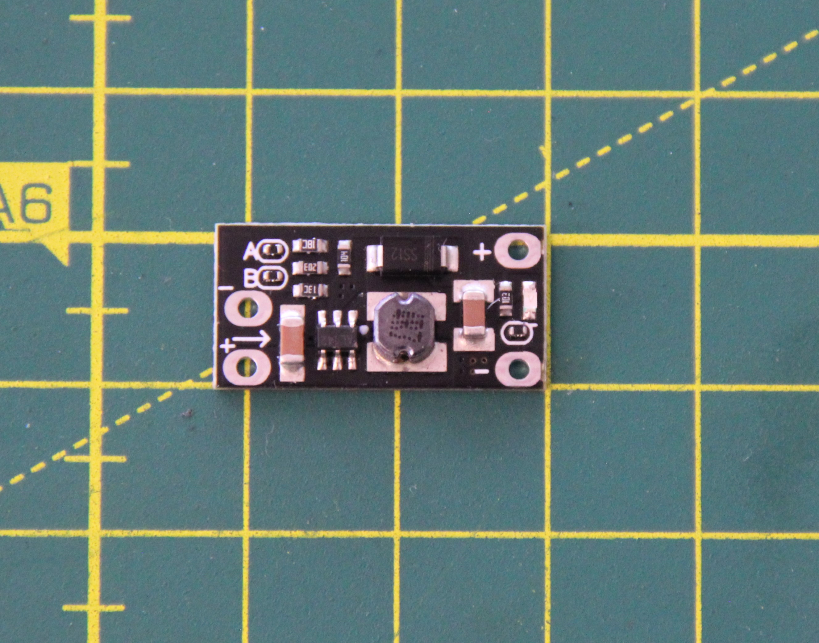
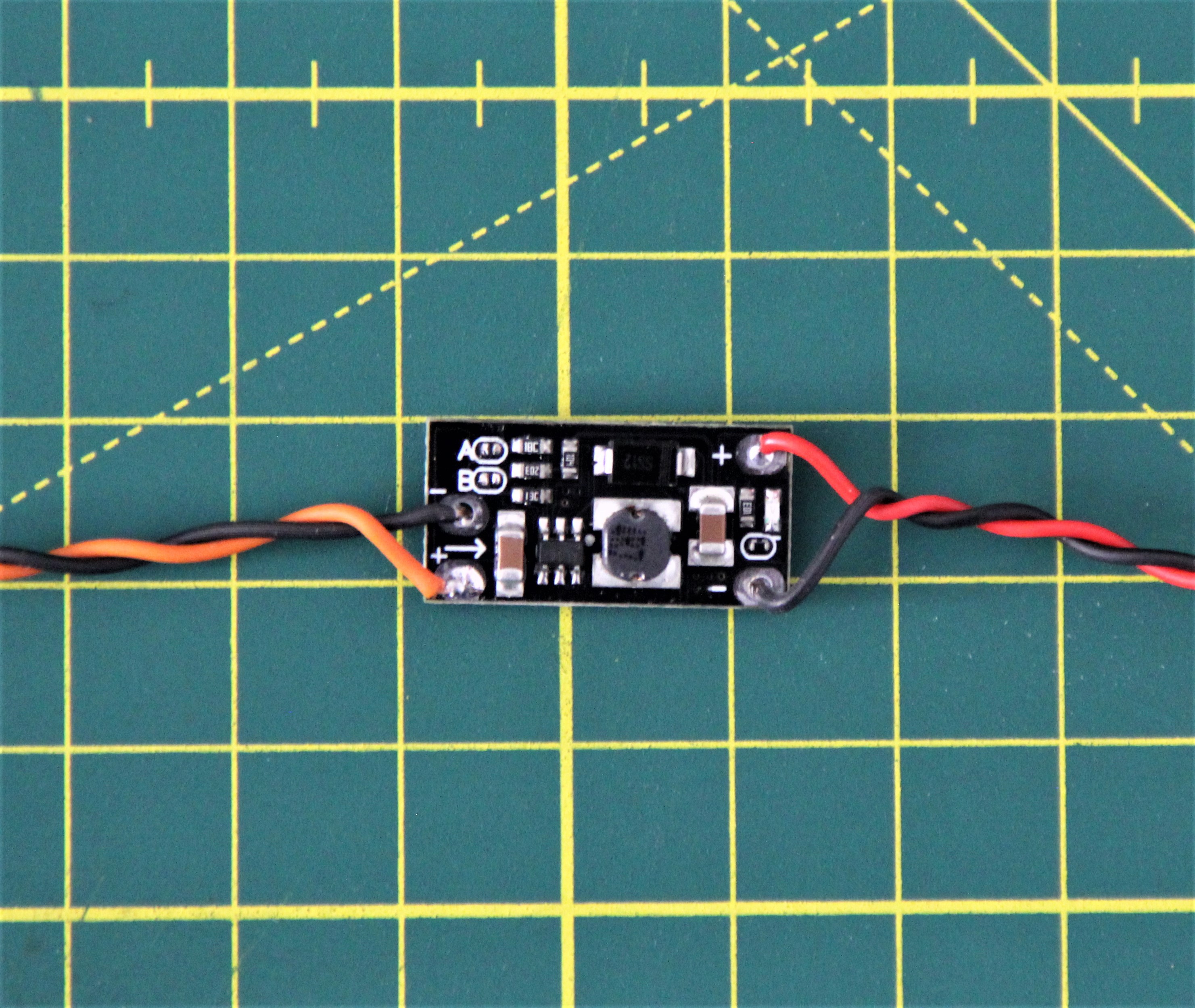
After that, I started working on electronics. First I desoldered the two resistors next to the letters "A" and "B" on the Boost Step-Up Converter Board Module. This is necessary to set the output voltage to 5V.
![]()
The TP4056-based LiPo charger must also be modified to reduce the charging current. Details can be found in my log TP4056-based LiPo charger modification.
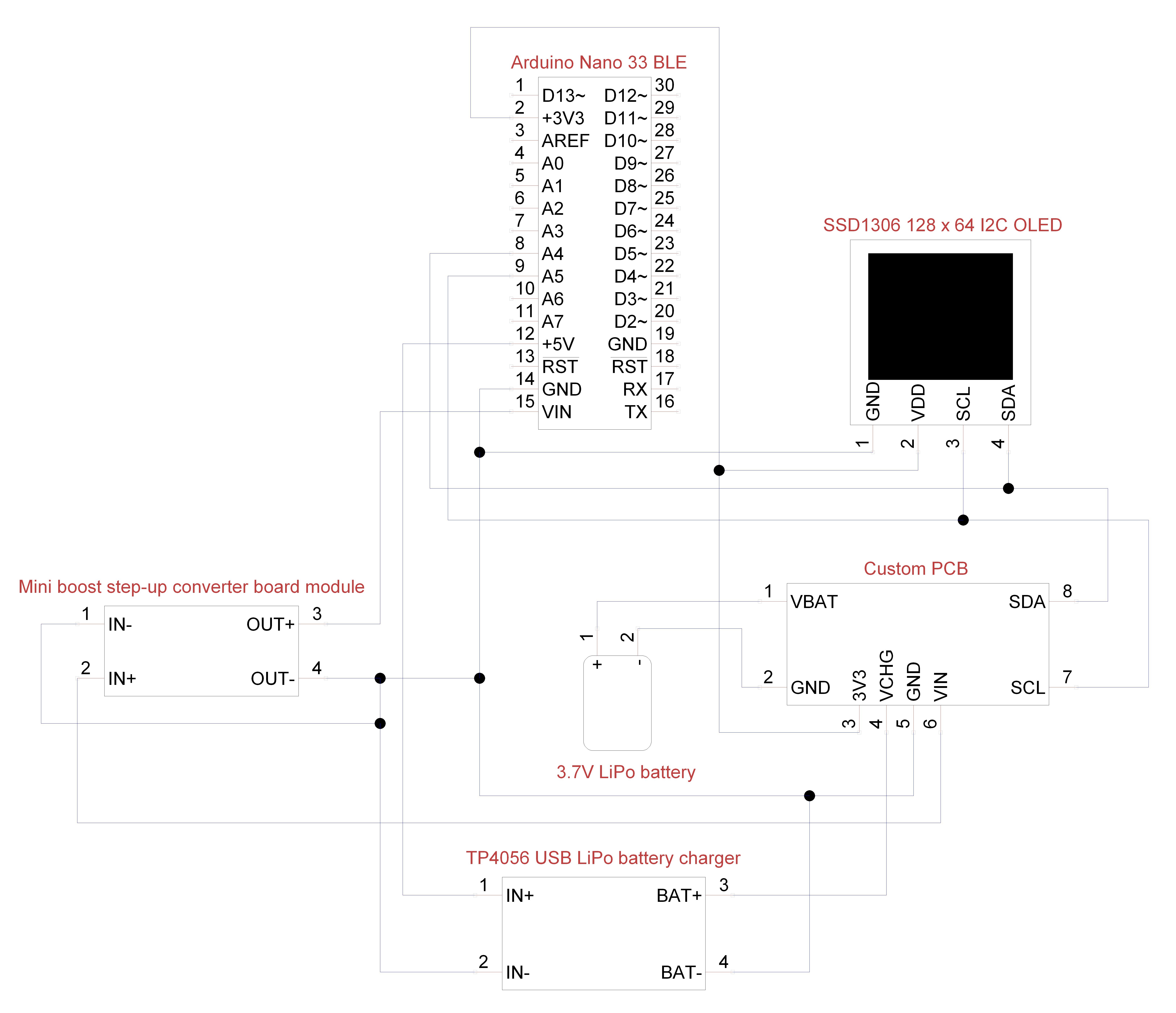
The wiring was then done as follows:
![]()
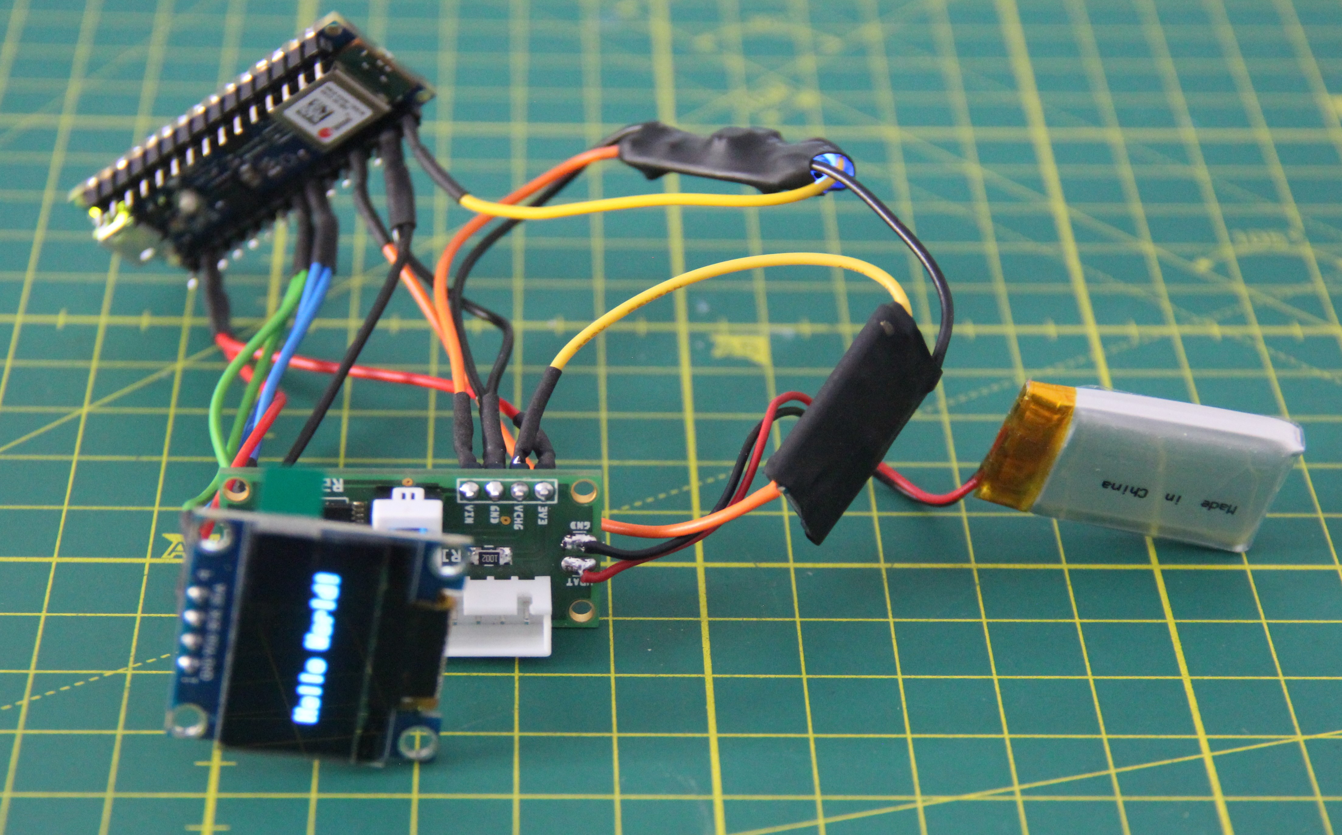
I insulated the LiPo charger and the step-up converter with heat shrink tubing to avoid accidental contact. Before installation, the electronics were tested.
![]()
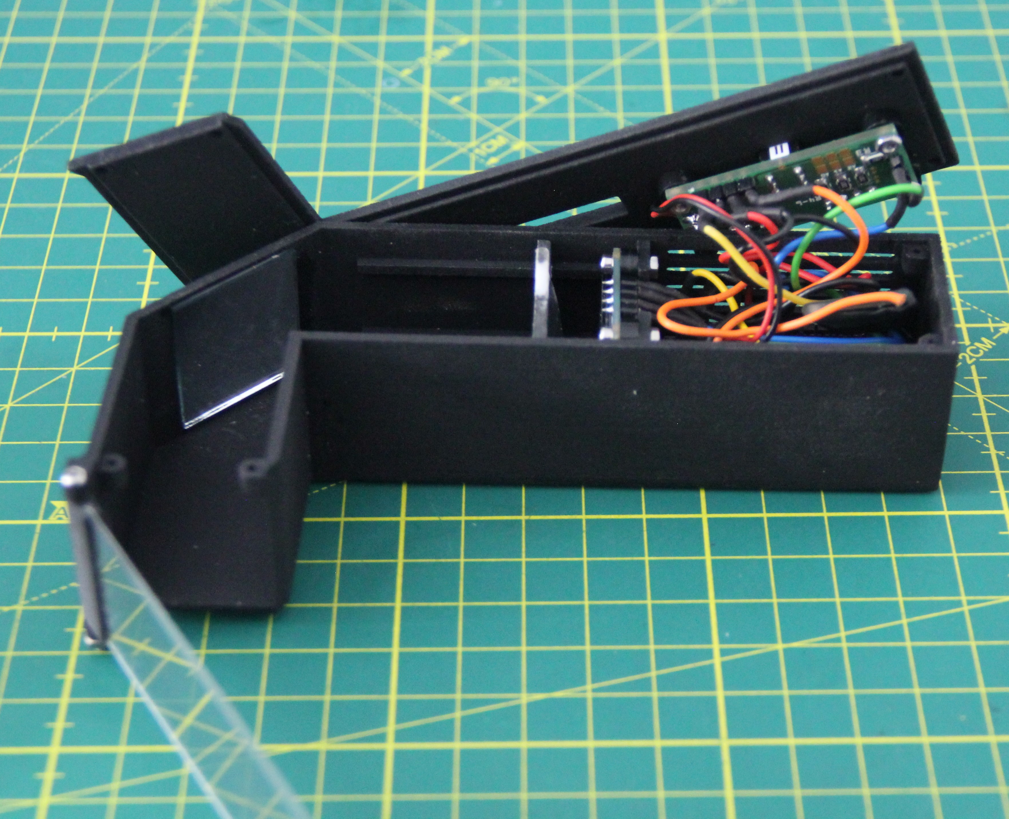
The Arduino Nano 33 BLE was attached with four self-tapping M1.5 x 6mm screws, the OLED, and the custom PCB with six M2 x 8mm screws, 3mm spacers, and the corresponding nuts.
![]()
The biconvex lens should be about 10mm in front of the OLED, the more convex side towards the OLED. The closer the lens is to the OLED, the smaller the image projected onto the microscope slide will be. Now the protective film can also be removed from the OLED.
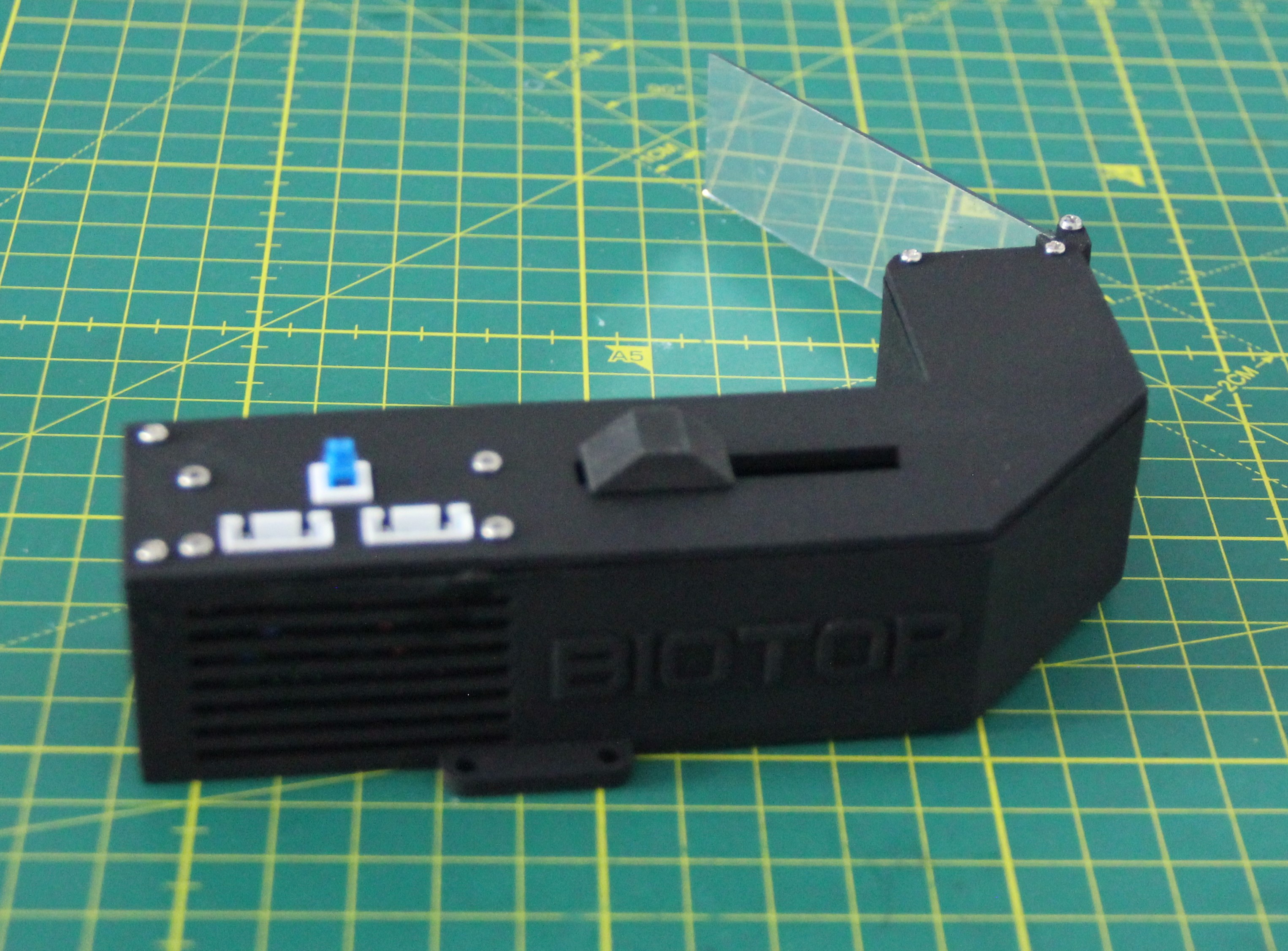
Finally, the AR glasses were screwed together with four M1.7 x 8mm screws and the sliding knob for the lens was inserted.
![]()
![]()
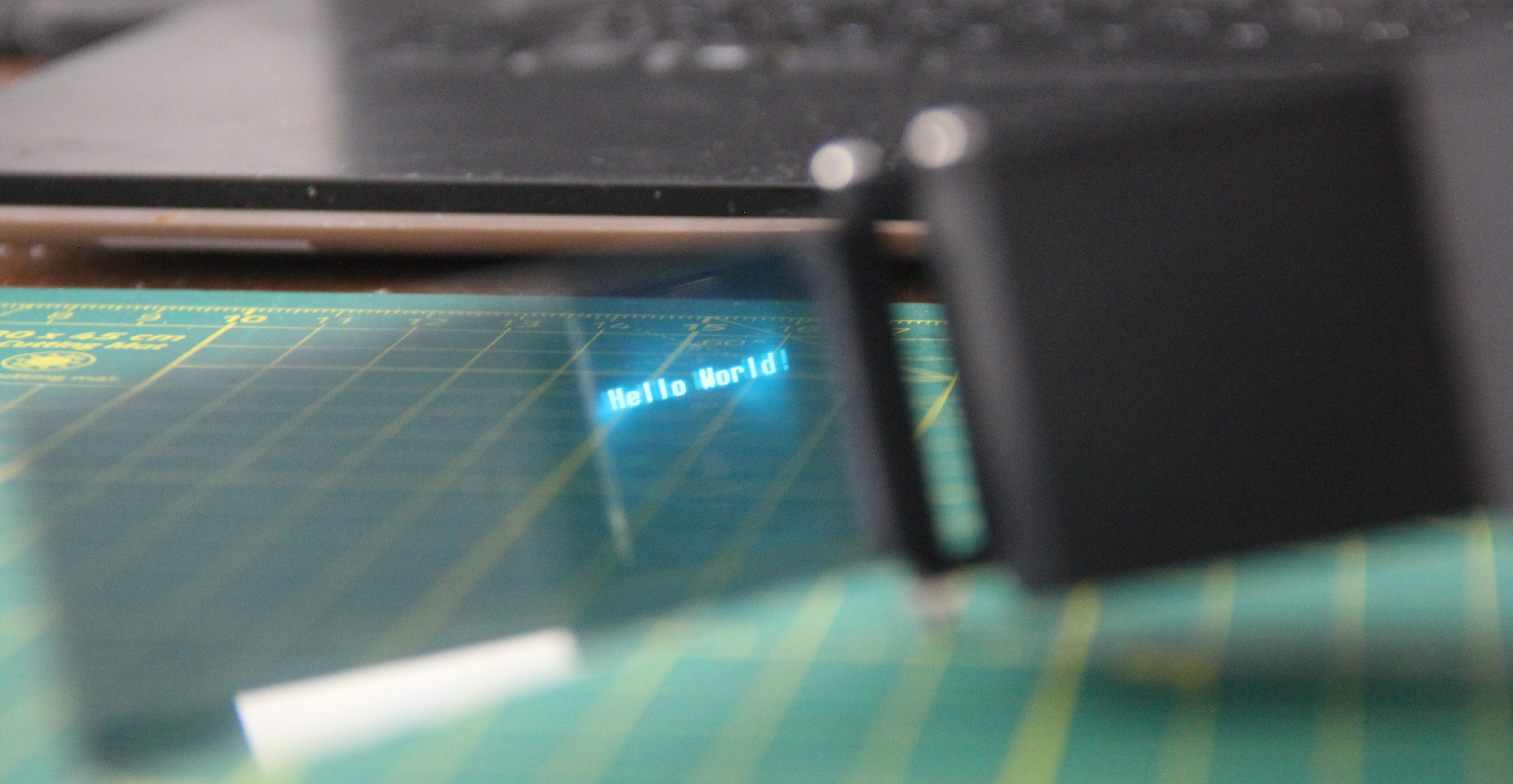
The glasses from the first-person viewpoint:
![]()
-
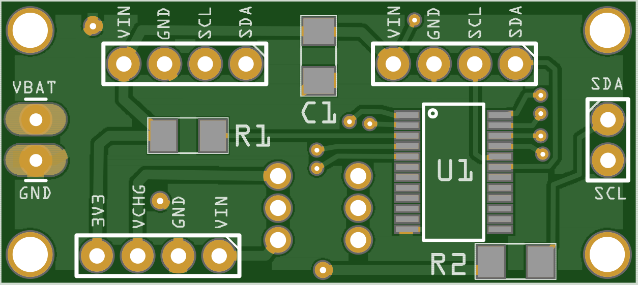
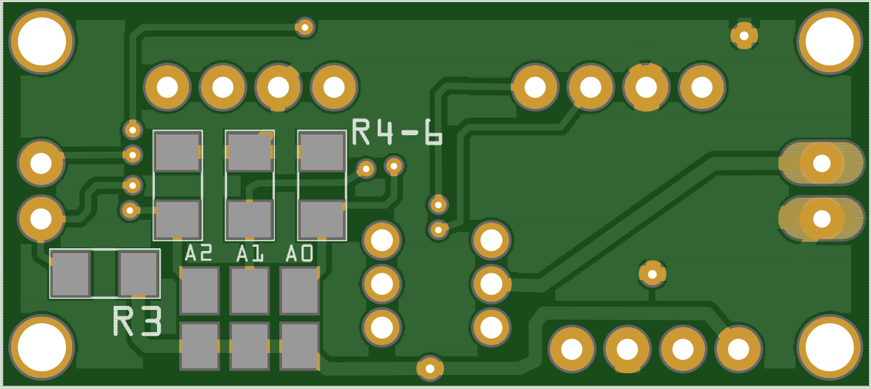
Custom PCB
04/06/2023 at 10:38 • 0 commentsOne custom board is needed for the project on which the I2C multiplexer, the connectors for the LiPo battery, the gas sensors, the IC2 bus, and the on/off switch are located. The PCB will be mounted in the AR glasses housing.
![]()
![]()
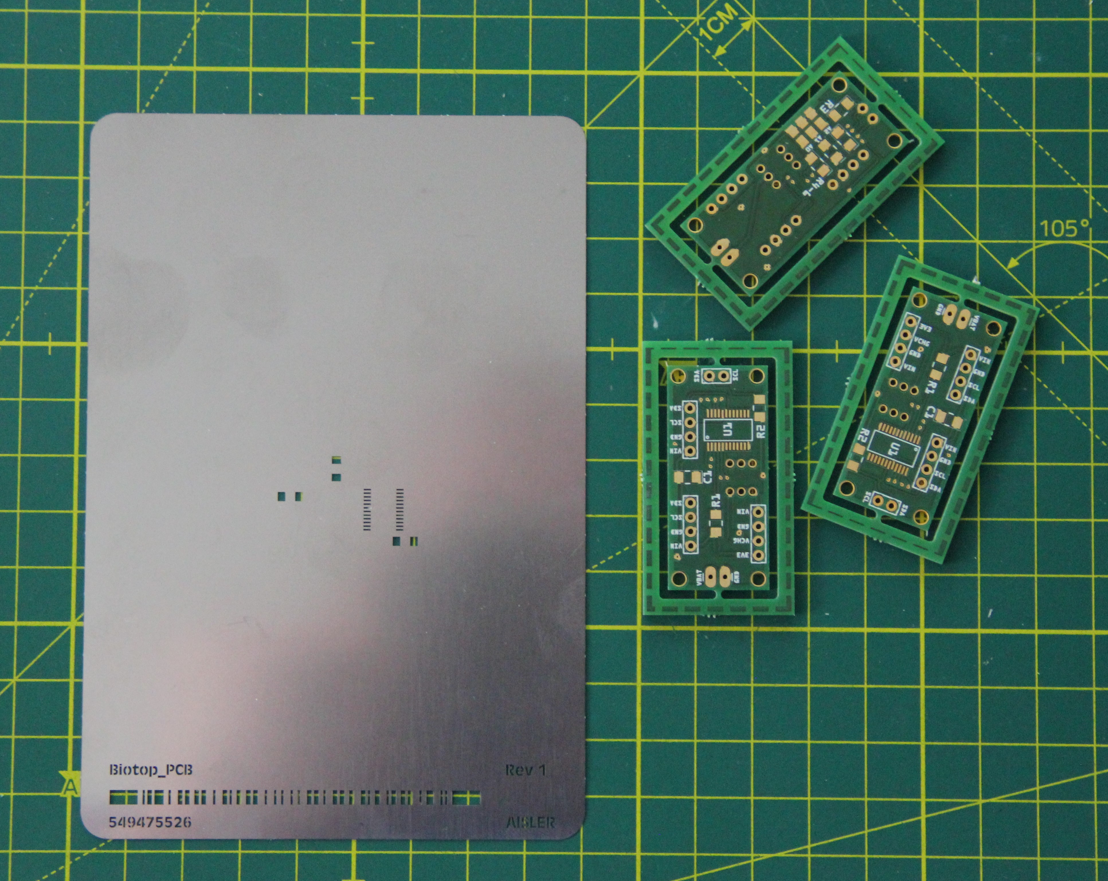
PCB and stencil for the top layer:
![]()
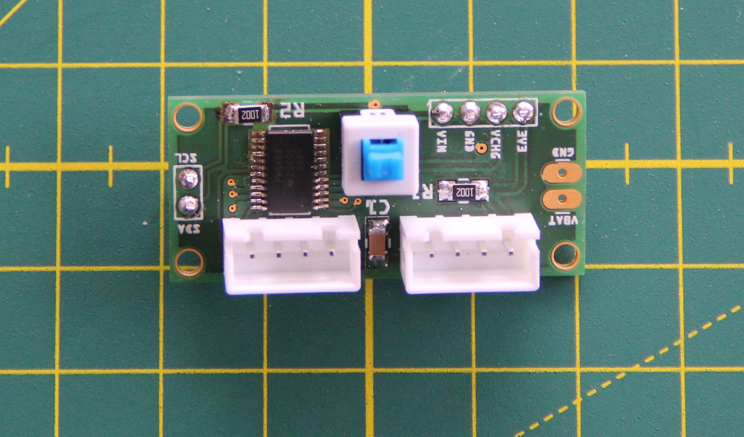
Populated PCB:
![]()
To check the function, I wrote a small test program for the Arduino Nano 33 BLE:
#include <Adafruit_SGP30.h> #include <Wire.h> Adafruit_SGP30 sgp1; // Define two classes Adafruit_SGP30 sgp2; // Function to select I2C BUS void TCA9548A(uint8_t bus){ Wire.beginTransmission(0x70); // TCA9548A address Wire.write(1 << bus); // Send byte to select bus number Wire.endTransmission(); } // Function to print the sensor values void printValues(Adafruit_SGP30 sgp, int bus) { TCA9548A (bus); Serial.print("Sensor number on bus"); Serial.println(bus); sgp.IAQmeasure(); Serial.print("TVOC "); Serial.print(sgp.TVOC); Serial.print(" ppb\t"); Serial.print("eCO2 "); Serial.print(sgp.eCO2); Serial.println(" ppm"); Serial.println(); } void setup() { Serial.begin(115200); // Start I2C communication with the Multiplexer Wire.begin(); // Init sensor on bus number 0 TCA9548A(0); sgp1.begin(); // Init sensor on bus number 7 TCA9548A(7); sgp2.begin(); } void loop() { // Print values for sensor 1 Serial.println("Sensor 1:"); printValues(sgp1, 0); delay(1000); // Print values for sensor 2 Serial.println("Sensor 2:"); printValues(sgp2, 7); delay(1000); } -
Agar instead of soil?
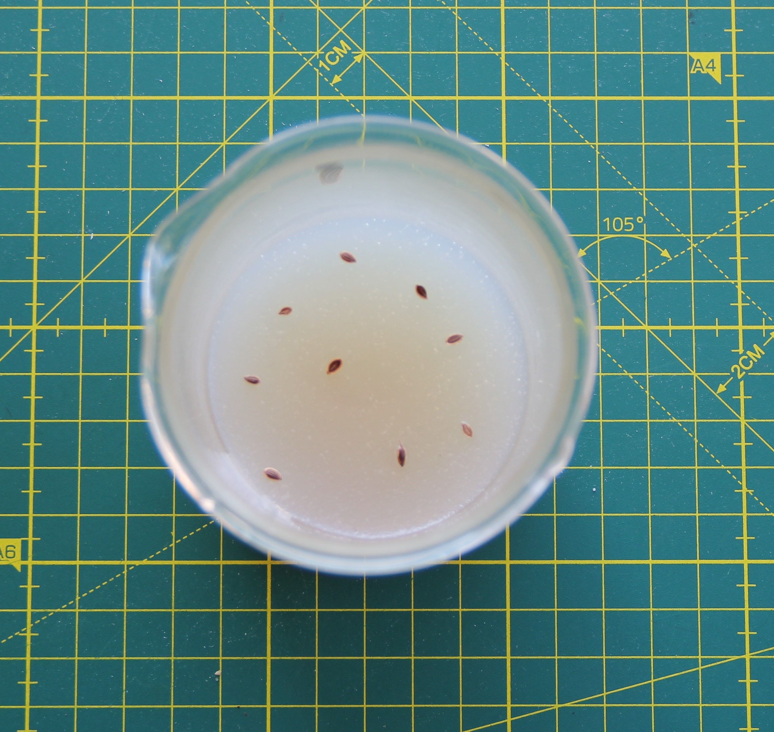
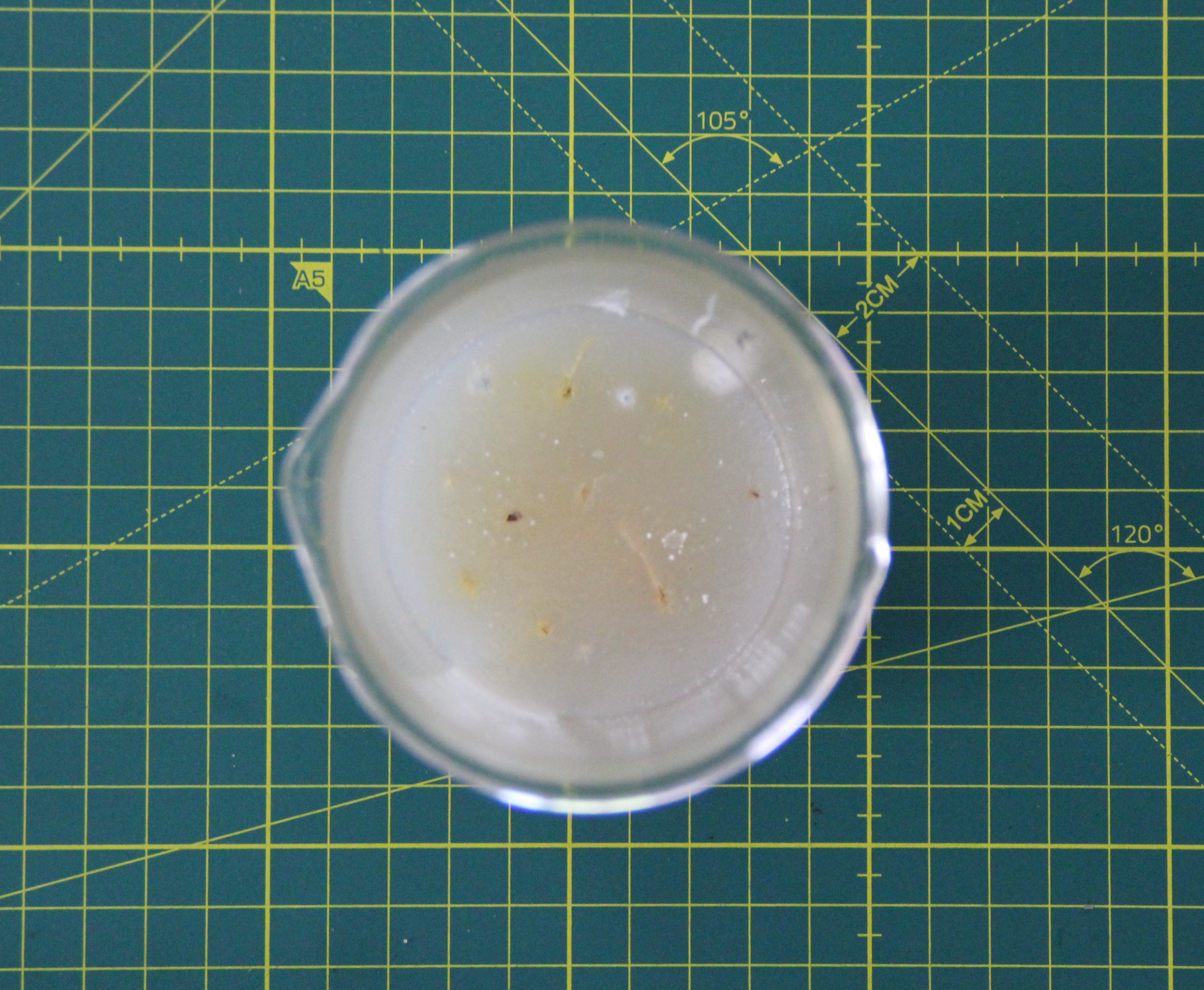
04/04/2023 at 08:26 • 0 commentsFor the first experiment, 4g of agar was boiled in 100 ml of distilled water, and 2 ml of universal liquid fertilizer was stirred in. After cooling, some dill seeds were placed on the agar surface and watered.
![]()
I then used a toothpick to make holes in the agar and pushed the seeds into the holes.
After a few days, the first mold cultures formed on the agar. I had not thought that this would happen so quickly. Some molds seem to be quite undemanding. I will let the experiment continue, as I am primarily interested in whether the seeds sprout and grow in the medium.
![]()
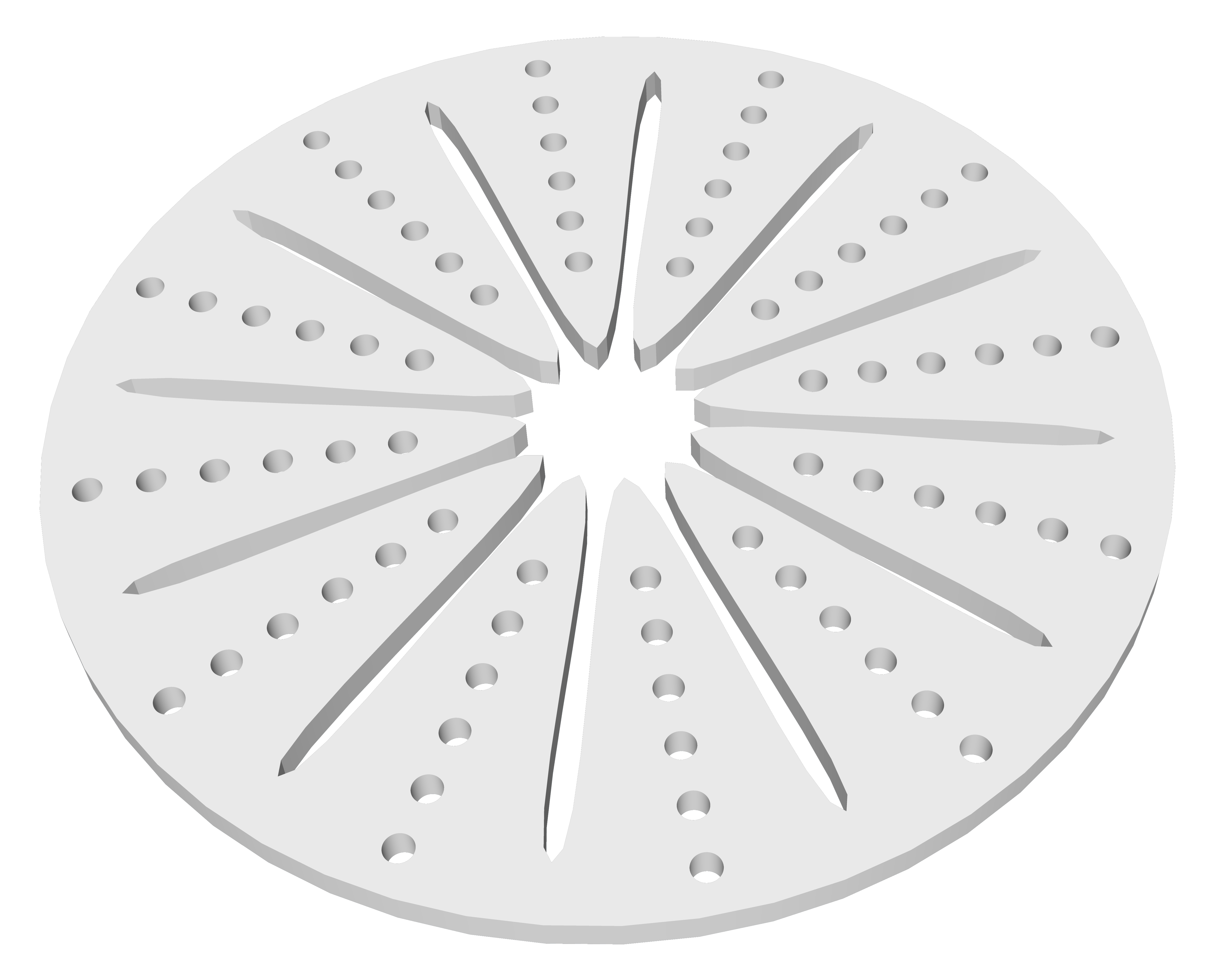
Another possibility would be sodium alginate, which gels when it comes into contact with calcium lactate and finds use primarily in so-called molar cuisine. Or simply a layer of soil, on top of it a layer of expanded clay pebbles, and finally a kind of retainer that retains the pebbles but is permeable to water and air.
![]()
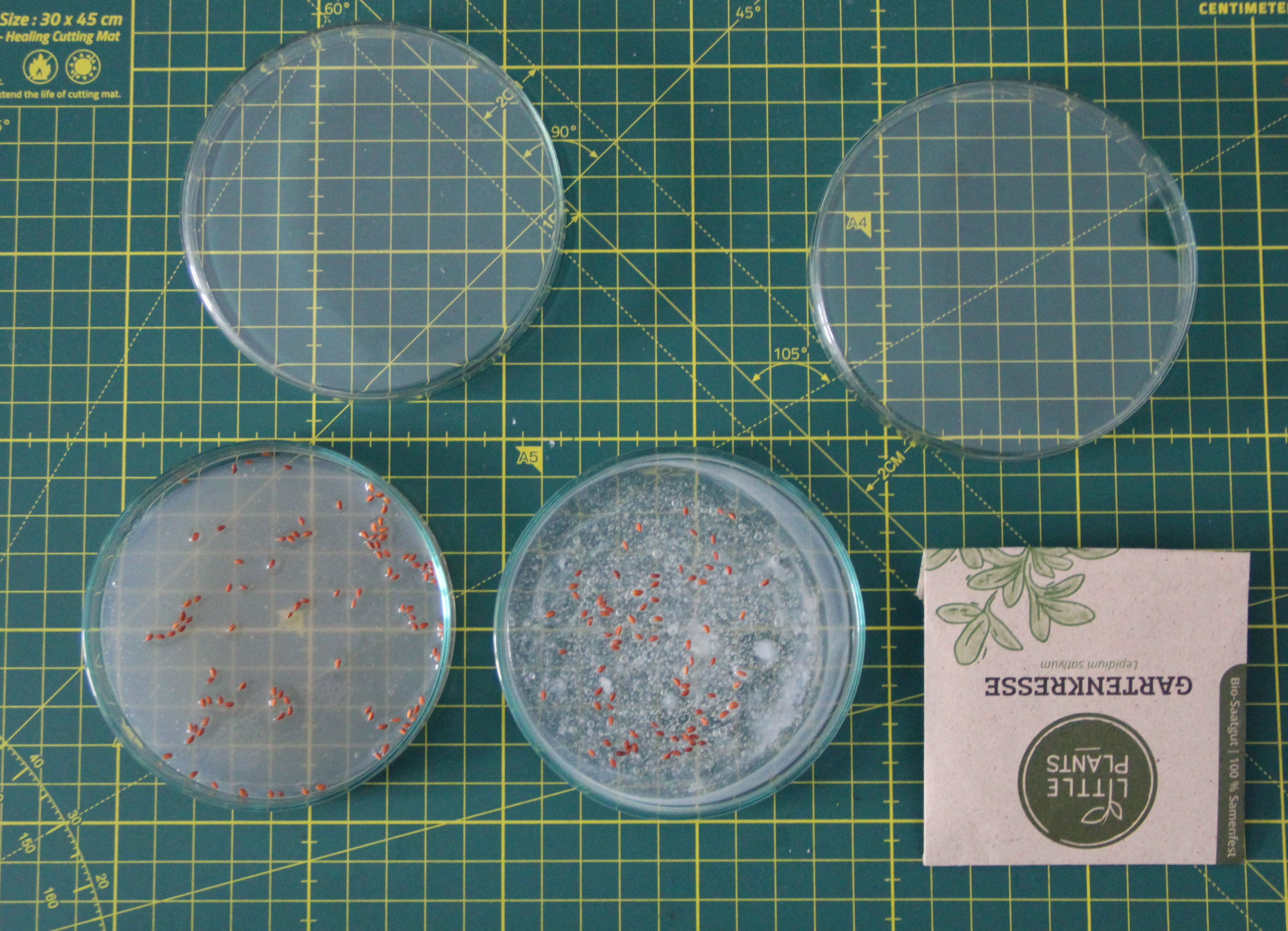
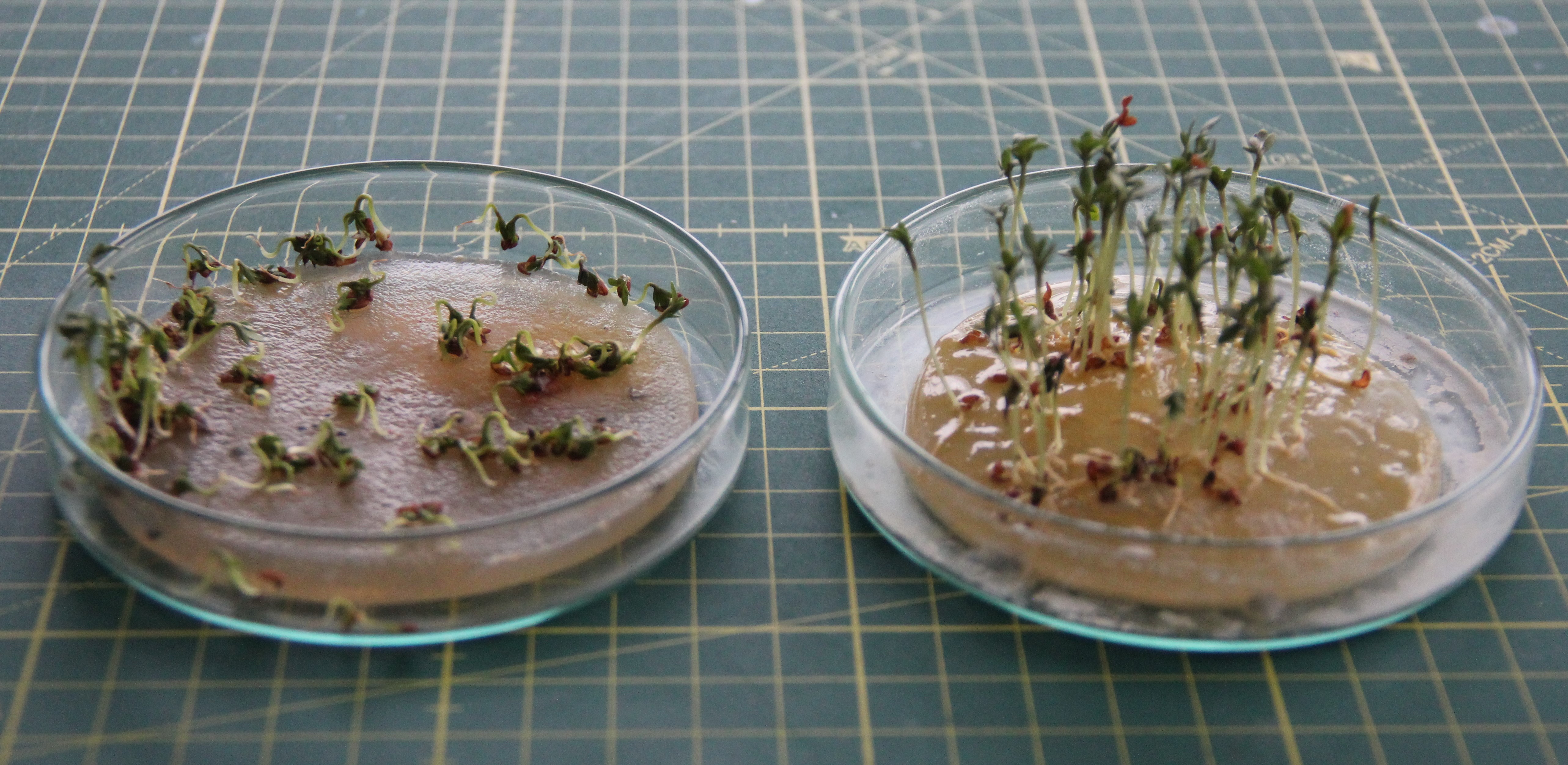
Since I am very interested in the theme, I started another series of experiments. The Petri dish on the left contains agar, and the one on the right contains sodium alginate, which I have set with concentrated calcium lactate solution. This time I use cress seeds (Lepidium satlyum) because they sprout much faster.
![]()
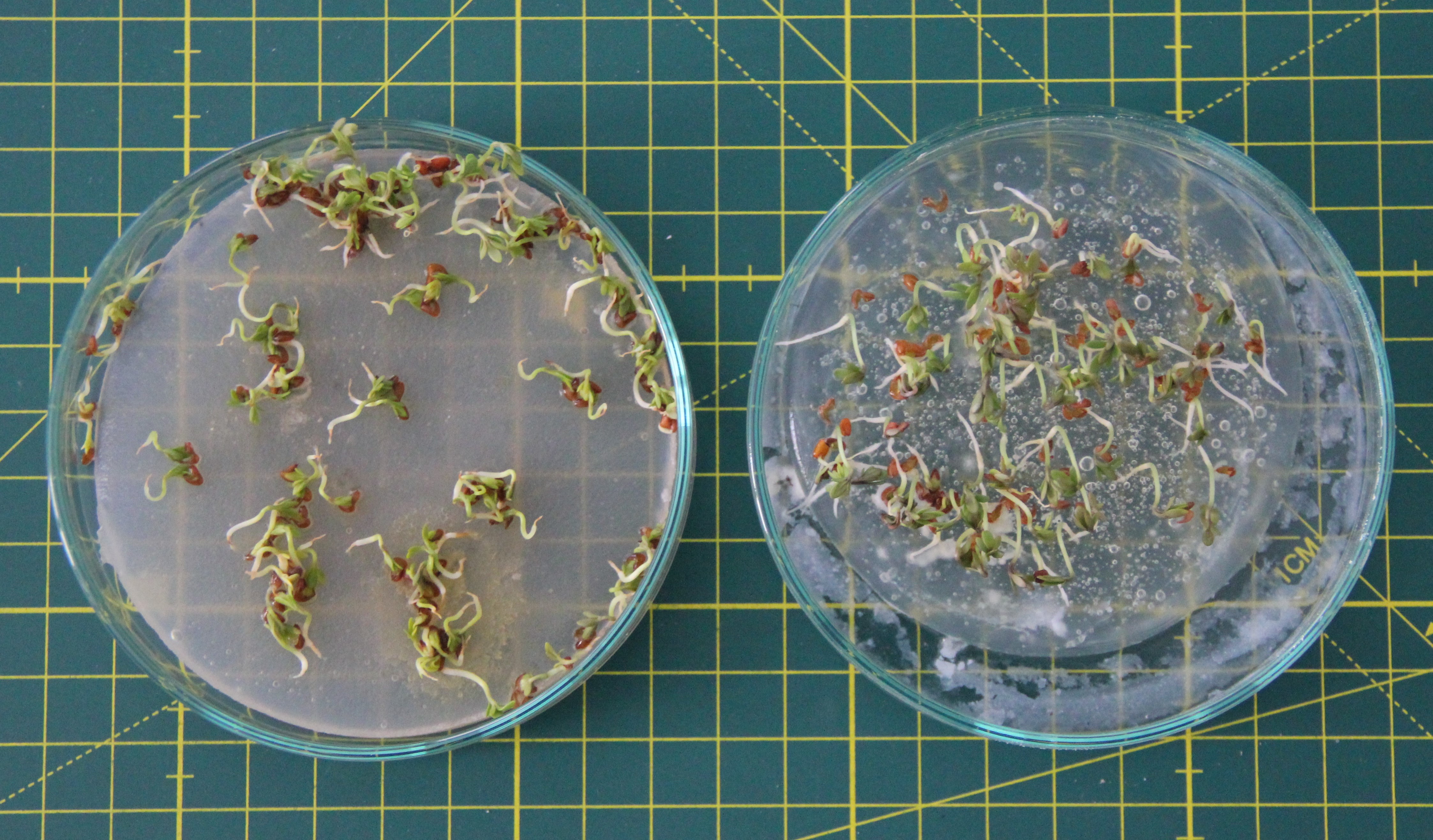
A few days later, the cress seeds sprouted. It seems that the cress grows faster on the sodium alginate substrate than on agar. I suspect it is because the roots penetrate the sodium alginate more easily than the agar. Both Petri dishes can be turned upside down and the plants adhere very well to the substrate.
![]()
A few days later it is even more obvious:
![]()
-
Air valves
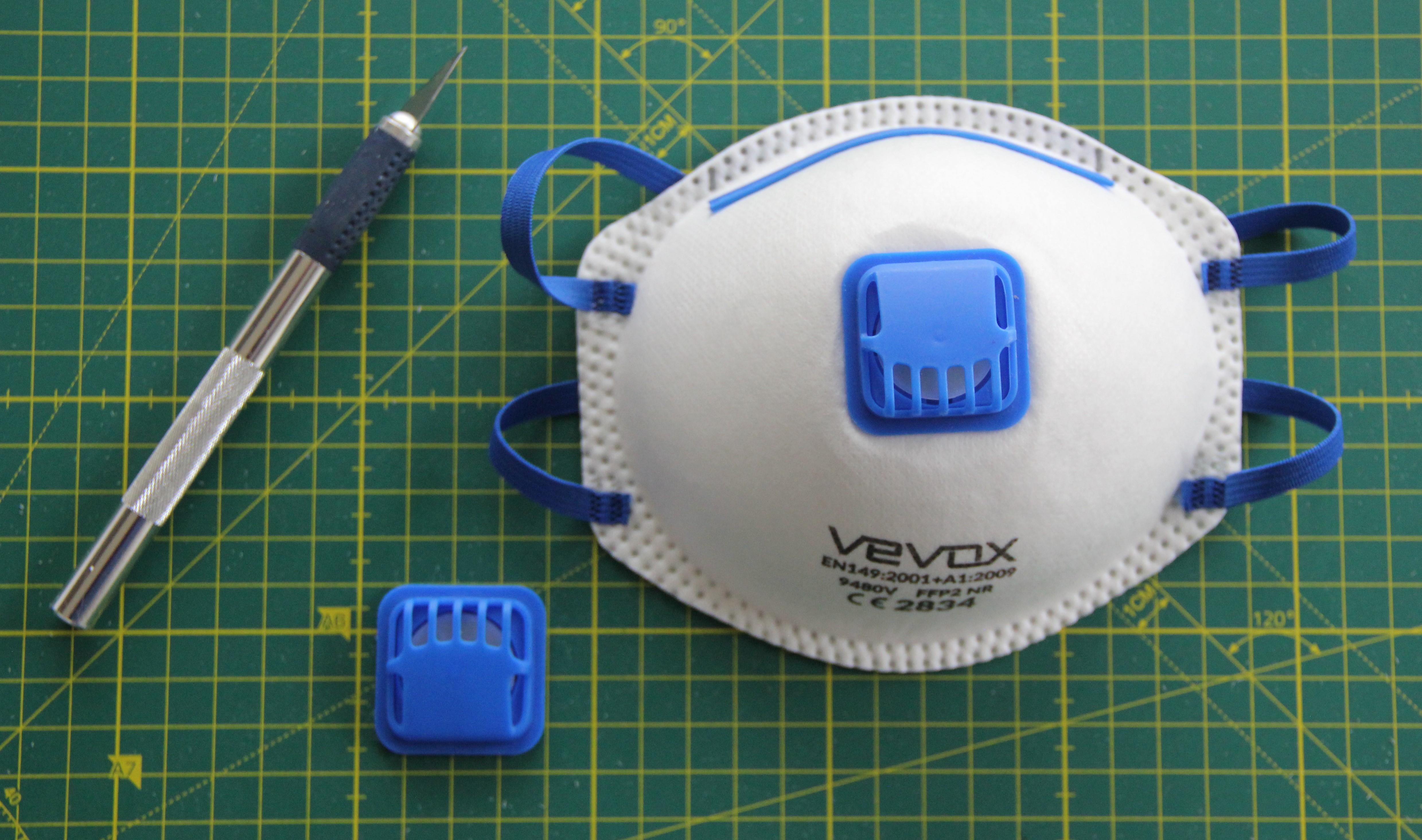
04/03/2023 at 10:53 • 0 commentsAir valves must be fitted in the two closing lids of the mini-biotopes, which allow inhalation via the biotopes but prevent exhalation. Exhalation takes place via corresponding valves integrated into the diving mask. I use a valve that can be found in some FFP2 masks for this purpose.
![]()
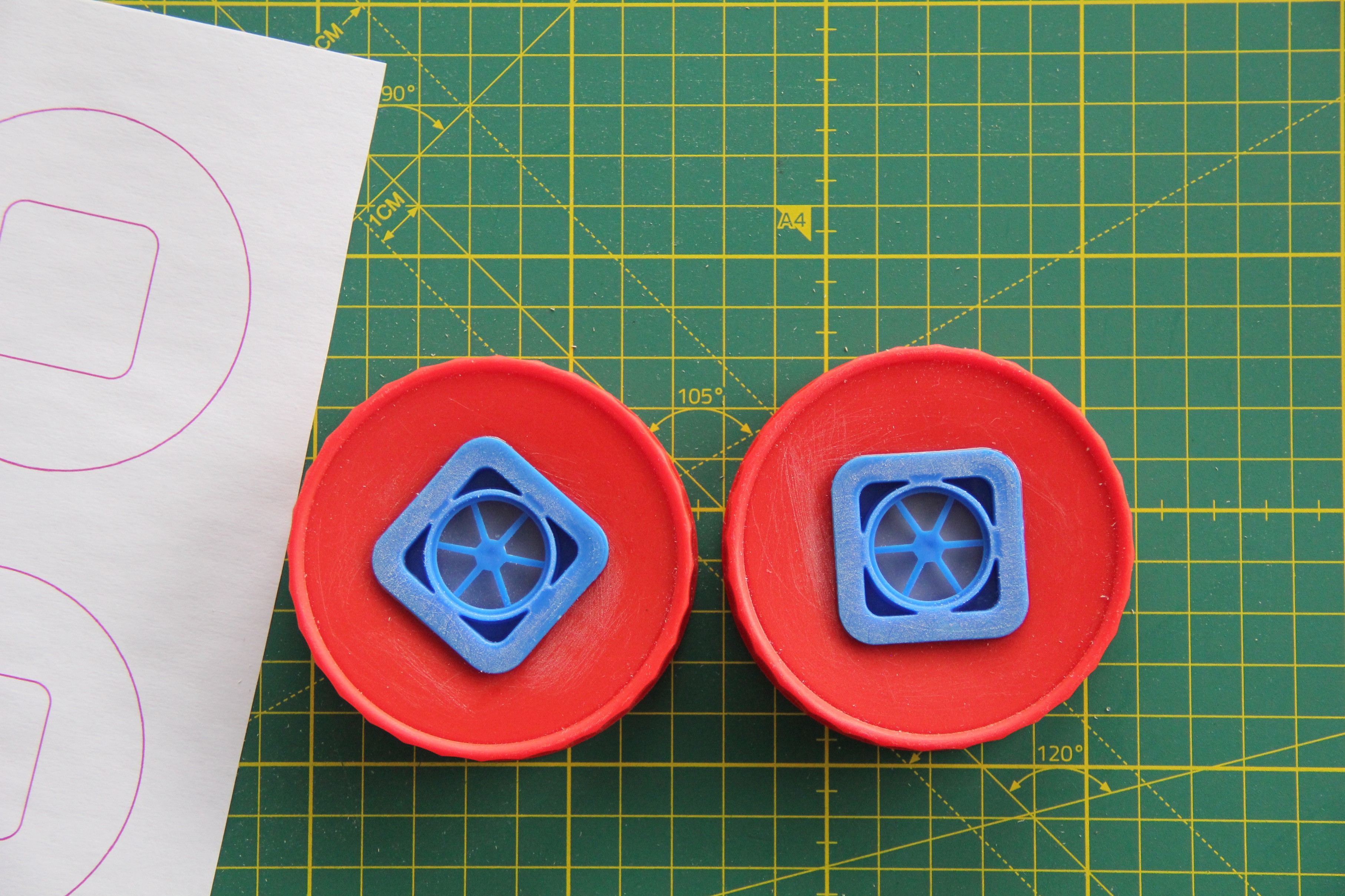
I drew stencils in Inkscape and applied them to the lids using spray adhesive. Then the cutouts were sawed out with the scroll saw, sanded, and cleaned with isopropanol before the air valves were glued in place with 2-component epoxy glue.
![]()
-
TP4056-based LiPo charger modification
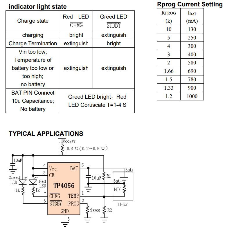
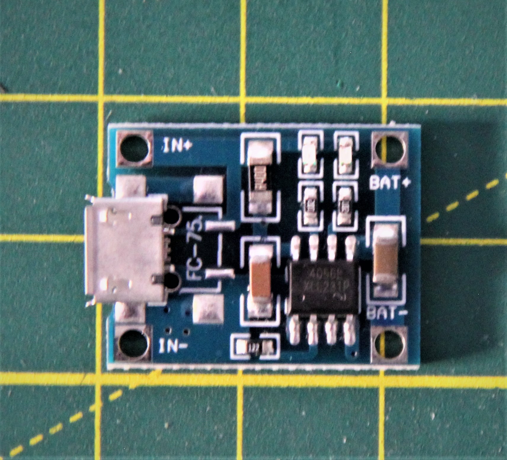
04/03/2023 at 09:10 • 0 commentsI use a TP4056-based LiPo charger with a micro USB connector. The charging current is 1A according to the manufacturer. But since I use a 250mAh LiPo battery, I need a lower charging current (max. 250mA). The following excerpt from the datasheet shows that the resistor at pin 2 of the TP4056 determines the charging current. So I have to change the resistor accordingly.
![]()
The charging current can be accurately calculated by the following formula:
The according resistor is located in the middle of the lower side of the PCB and is labeled with "122":
![]()
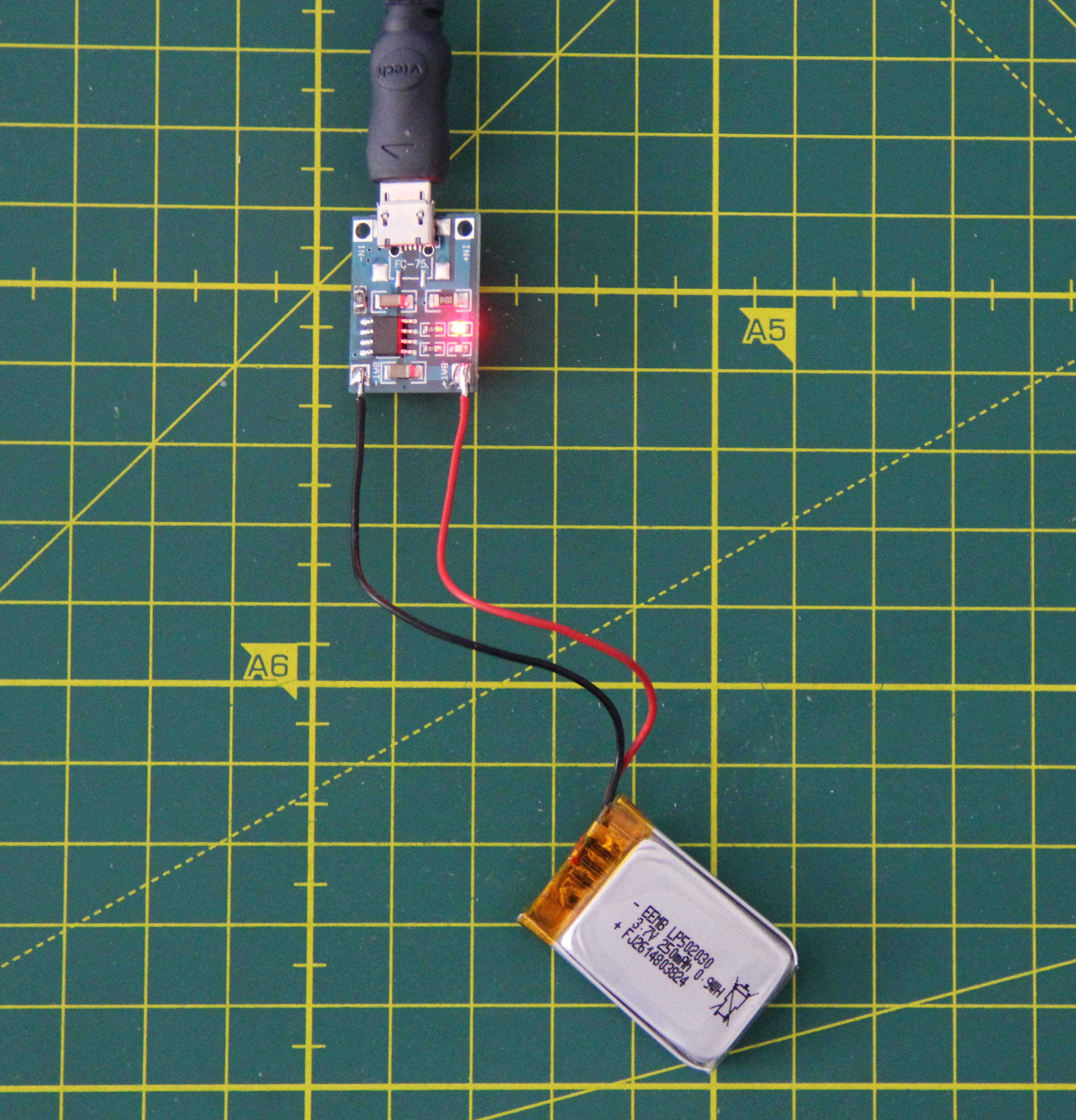
Testing the charger after modification:
![]()
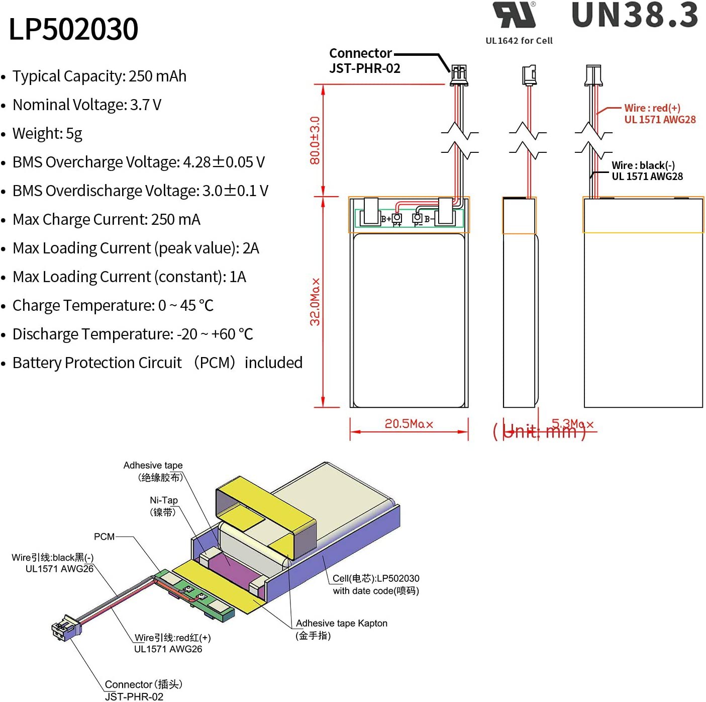
The LiPo battery I use has the following characteristics:
![]()
The first DC-DC step-up converter I tested was total garbage. Even with a constant input voltage, the output voltage fluctuated consistently over 1 to 2V. The following one is fine. The output voltage can be programmed via two solder jumpers.
![]()
-
Arduino Nano 33 BLE
04/02/2023 at 14:04 • 0 commentsIMU
The nice thing about the Arduino Nano 33 BLE, besides the Bluetooth, is that it has an IMU on board. We can use it as a human-machine interface for the AR glasses. To do this, the Arduino_LSM9DS1 library needs to be installed. An example code for the accelerometer is shown here. The accelerometer can also be used to go into power save mode when no movement is detected for a certain time, for example during charging. In addition, a warning can be issued if one takes critical positions while wearing the mask.
U8x8 lib
The U8x8 library works without problems with the Arduino Nano 33 BLE. An unnamed I2C 128x64 OLED was used for testing.
Adafruit SGP30 lib
Also the Adafruit SGP30 library works without any issues with the Arduino Nano 33 BLE.
-
Started to design the AR glasses
04/01/2023 at 08:32 • 0 comments![]()
Biotop
A mask that filters pollutants from the air in a biological way.