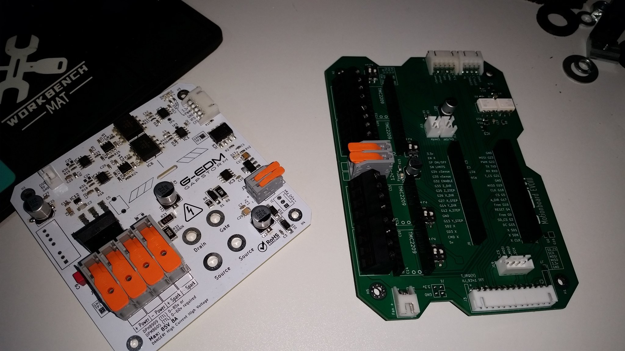
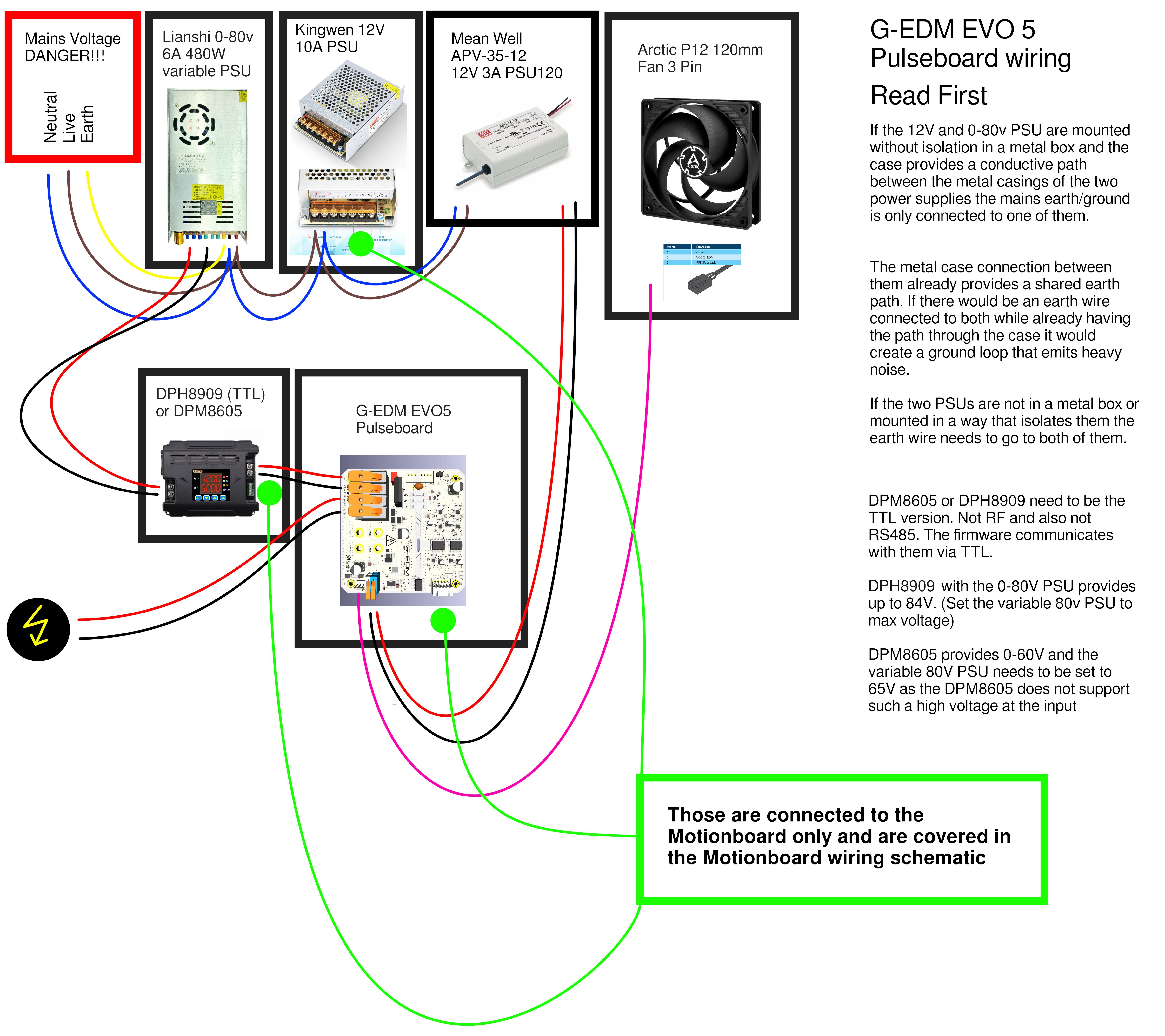
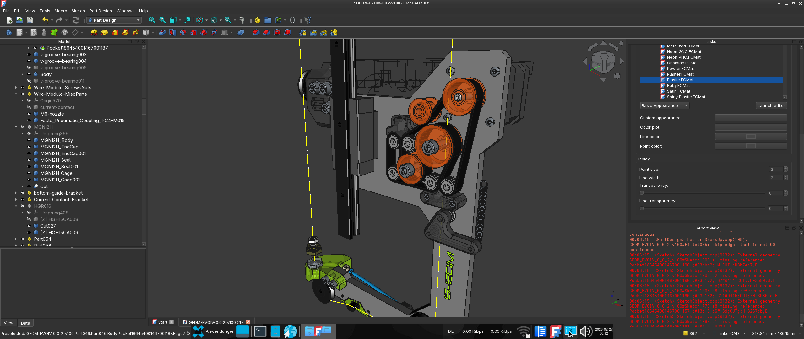
The G-EDM ( new video )
The final version of the control panel:
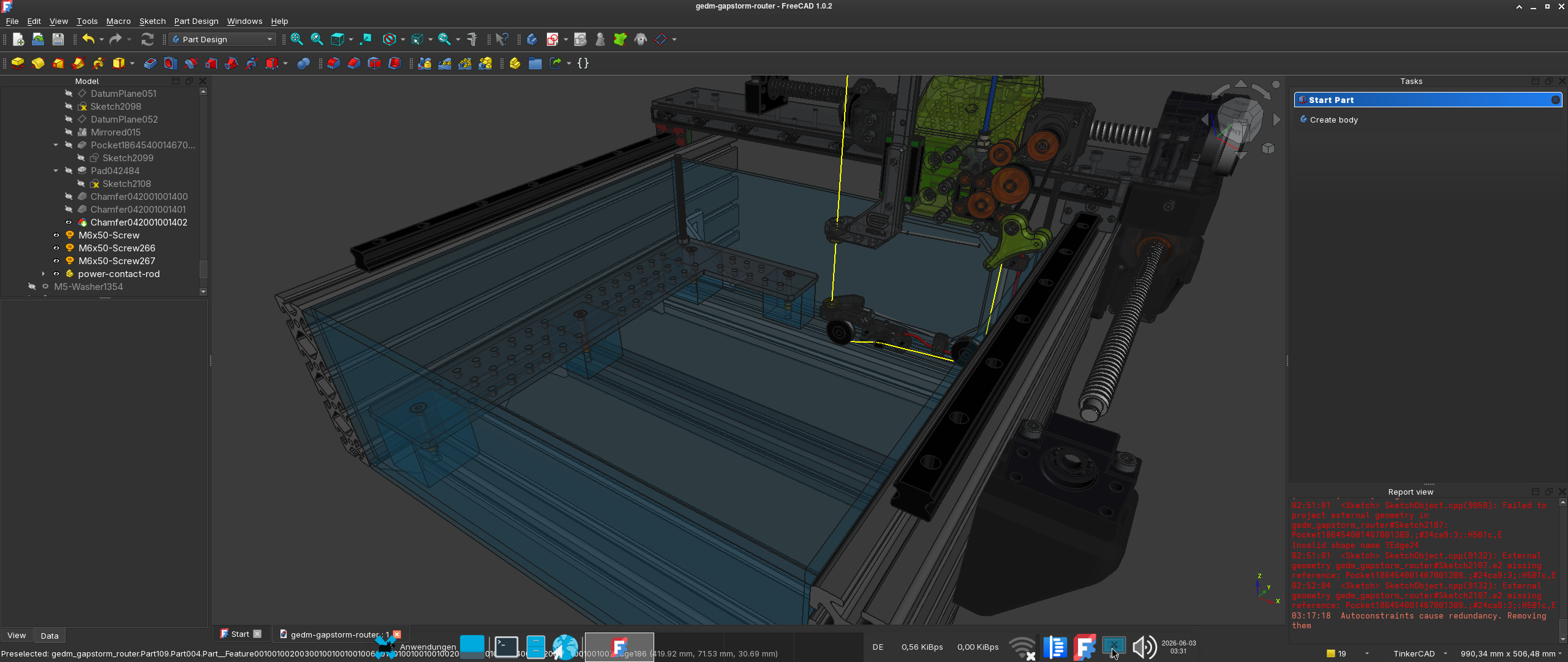
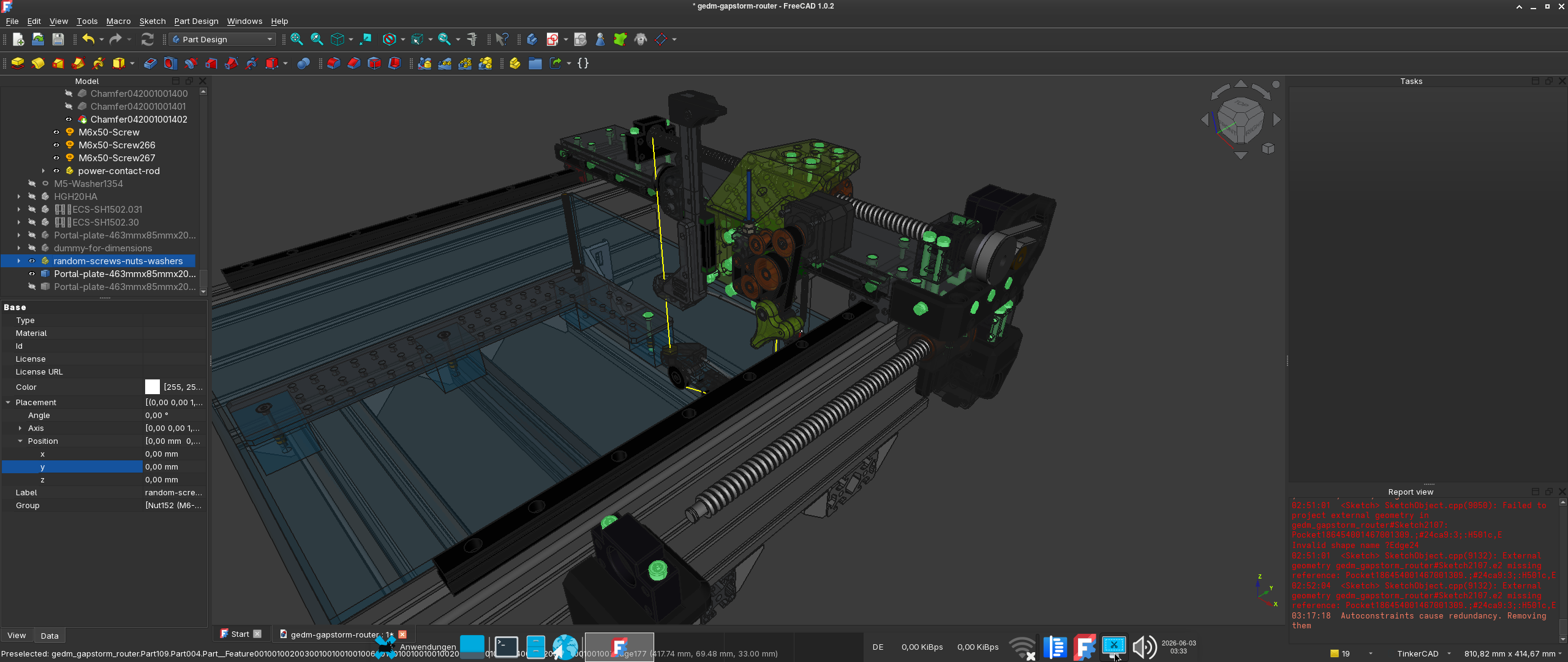
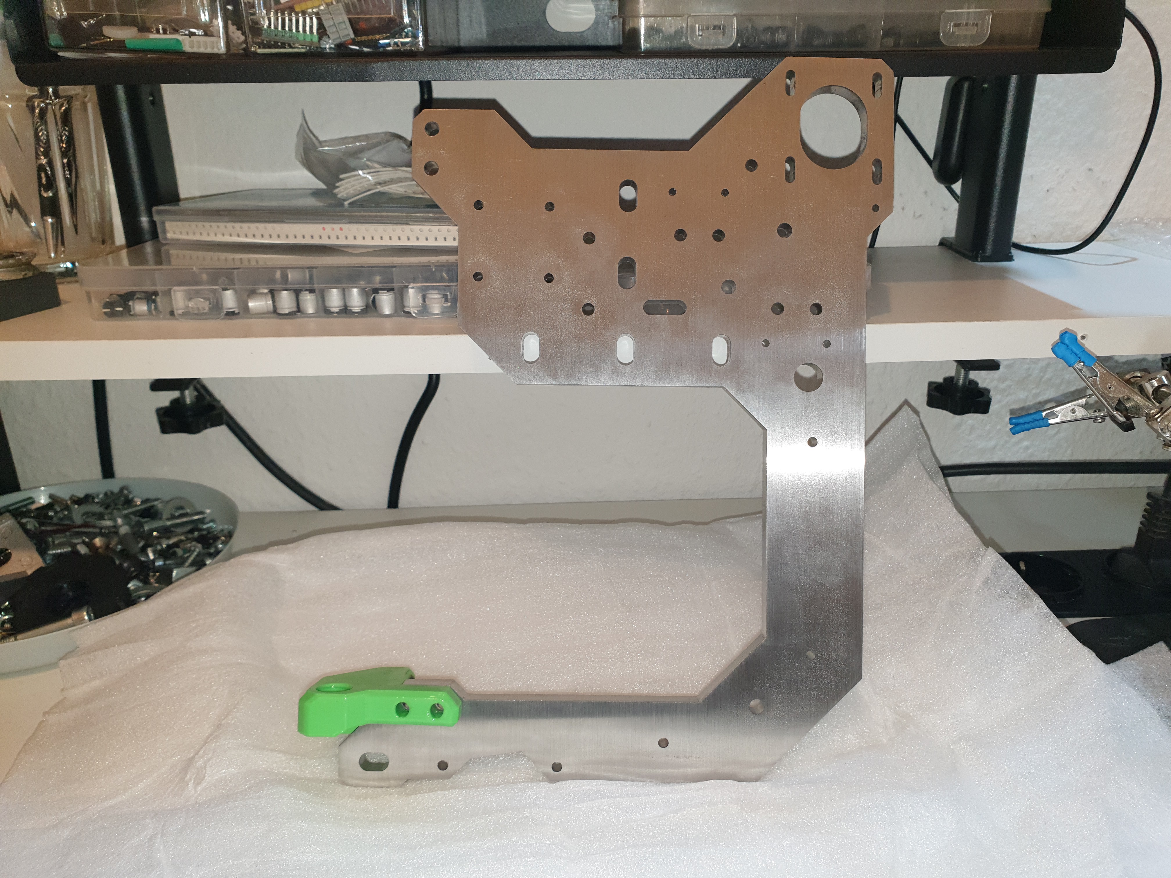
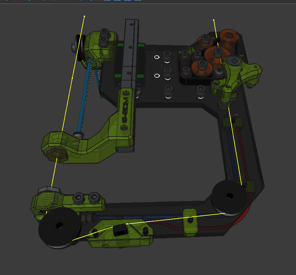
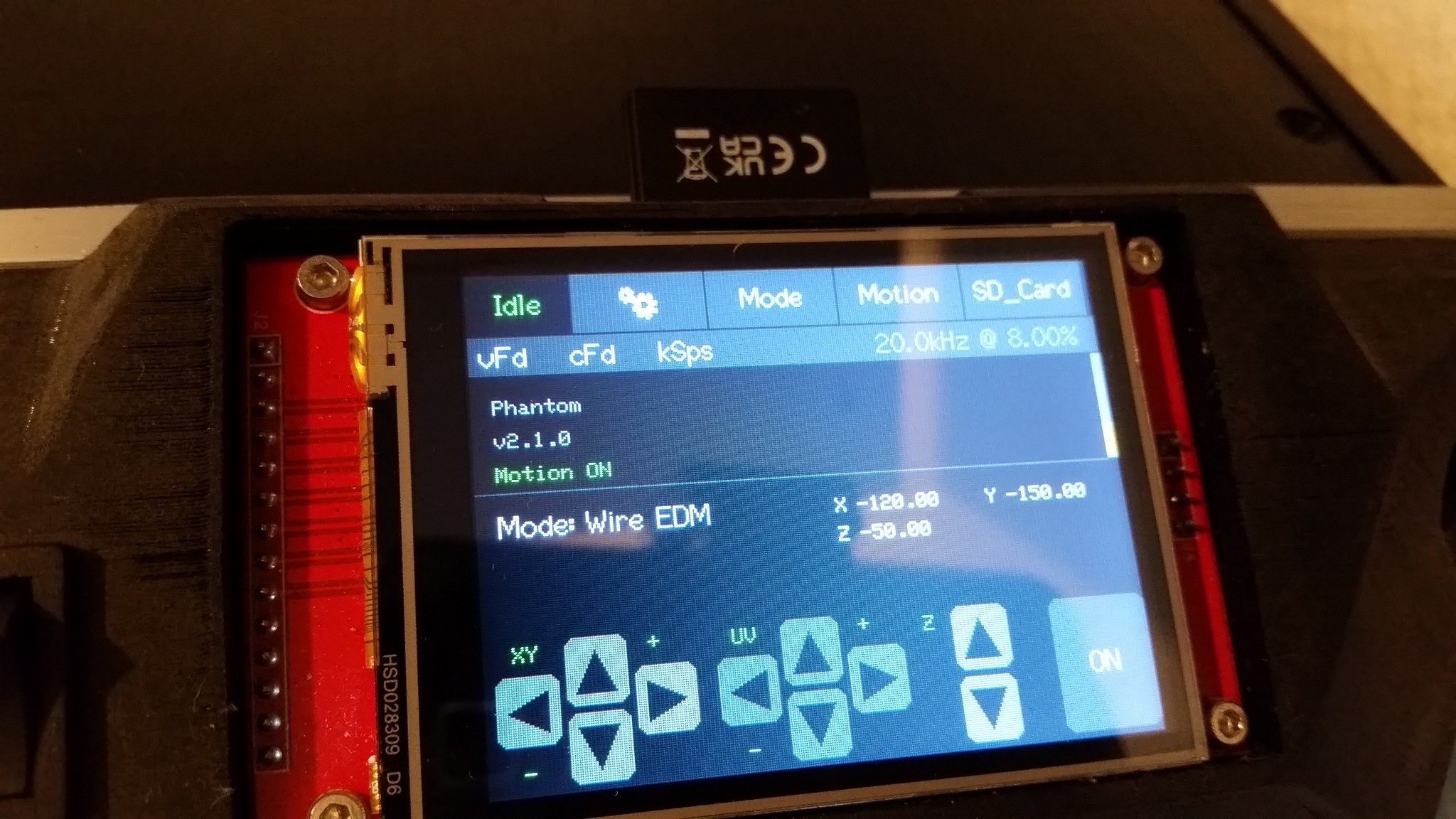
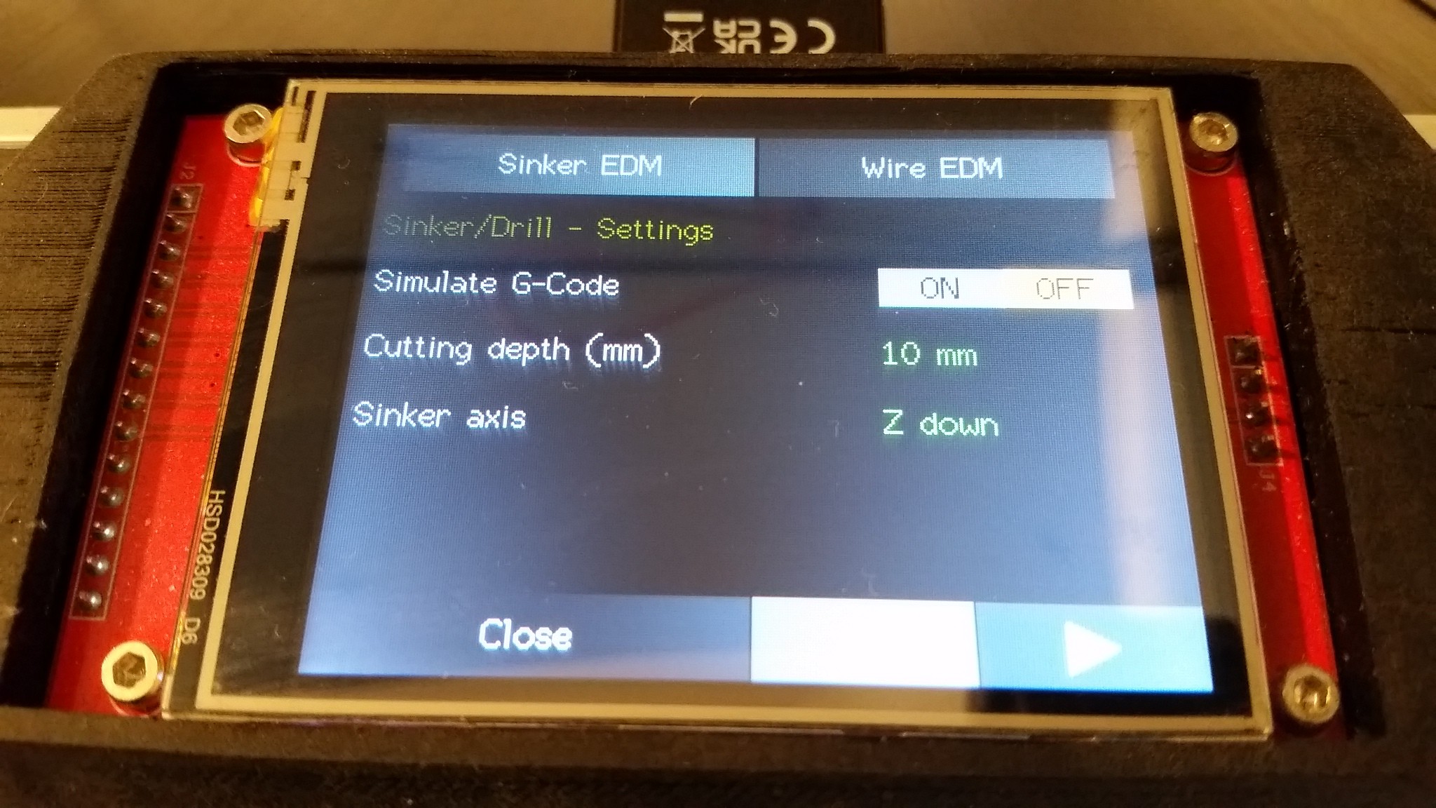
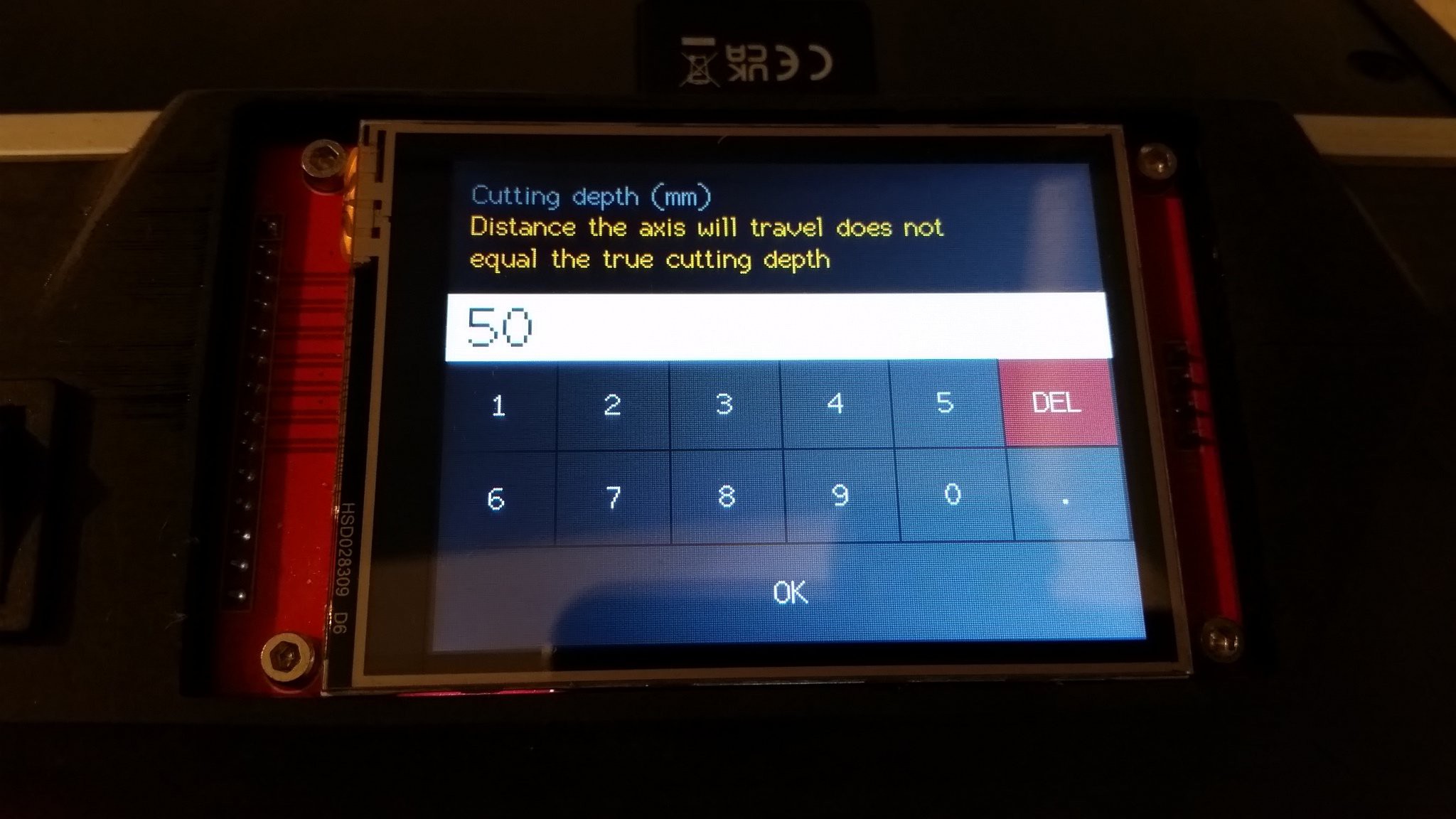
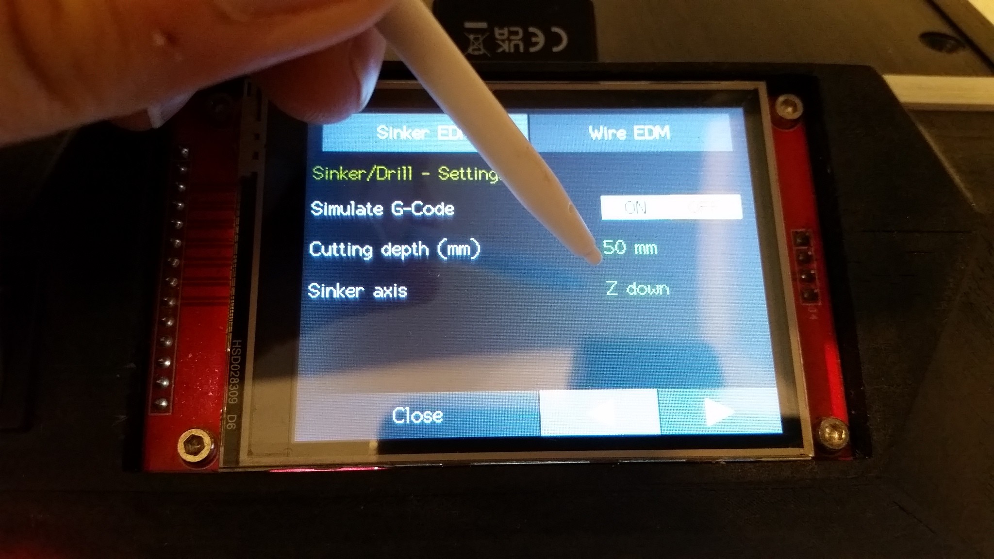
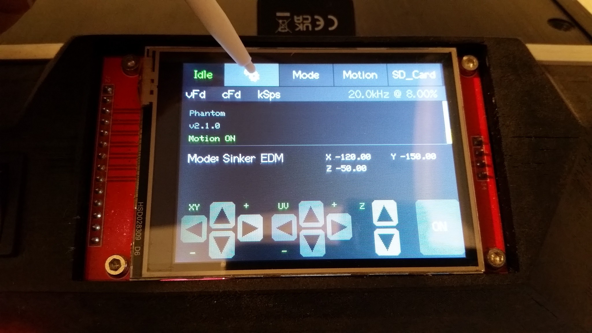
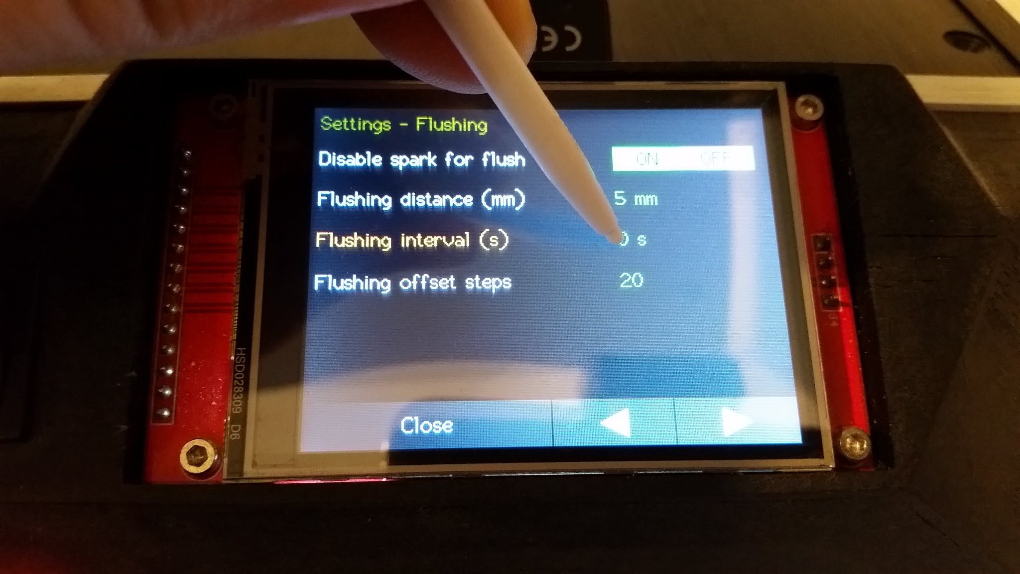
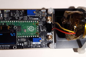
The G-EDM is an electrical discharge machine that supports sinker EDM, EDM engraving, EDM drilling and Wire EDM operations. #Drahterodieren
To make the experience fit your profile, pick a username and tell us what interests you.
We found and based on your interests.
The G-EDM ( new video )
The final version of the control panel:
The current router works very nice but there is so much room left to improve things. Especially the external control box adds to the footprint. The next one will have everything integrated.
Integrated electronics
Less weight
Cheaper
Easier to build
Great day for DIY EDM. The G-EDM won the first prize at the 7th PCBway design contest.
https://www.pcbway.com/blog/News/Meet_the_Winners_of_the_7th_Project_Design_Contest_f25c1e31.html
And there is also a new controlpanel on Github that can be mounted from the front and gives easier access if needed:
https://github.com/G-EDM/EVOIII-ControlPanel
And another major update is a new firmware release that has many bugs fixed and comes with a full makeover of the user interface:
https://github.com/G-EDM/PhantomEDM
Meet the Phantom
New firmware is available on github. It is a major update. many bugs where fixed. The UI got a full makeover and it just looks so much better now.
Available on Github:
https://github.com/G-EDM/PhantomEDM
Preview:
G-EDM EVOIII
The new EVOIII board provides a single PCB containing the pulse stage and the sensing stage. It replaces the EVOII pulseboard and the EVOII sensorboard.
The EVOII Cube is a cool looking piece of Art but it is hard to manufacture. To reduce build costs and make it easier to produce the EVOIII PCB was designed. Specs and performance of both versions is the same. There is one difference: The EVOIII uses a single gate driver IC while the EVOII cube has a discrete gate driver circuit. At higher frequencies they don't switch identically and the cube needs a slightly higher duty cycle.
The board provides two isolated analog feedbacks and also isolates the PWM to drive the mosfet gates.
Here are the links to order the boards directly and build them on your own.
All three boards are needed to build a G-EDM.
Pulseboard:
https://www.pcbway.com/project/shareproject/G_EDM_Low_budget_DIY_Wire_EDM_machine_pulseboard_8975f488.html
Sensorboard:
https://www.pcbway.com/project/shareproject/G_EDM_Low_budget_DIY_Wire_EDM_machine_sensorboard_24b74366.html
Motionboard:
https://www.pcbway.com/project/shareproject/G_EDM_Low_budget_DIY_Wire_EDM_machine_34e1e043.html
The project is almost finished and so far everything works acceptable.
The new concept was able to cut 30mm steel and also 2mm stainless steel.
PCBway helped a lot developing the PCBs and I think they deserve a little fan art for their great work.
The total cut took three hours. This is very slow and based on the feedback shown on the UI scope it should be possible to adjust the settings to make it in 1 hour.
The settings file is the same that made the 30mm cut and seems bulletproof. Not a single issue on this cut except one related to the mechanics.
The X axis belt walked off the idler bearings and finally fully popped off the pulley. That happened at the bottom of the W and from there on the X position is a little off. Shit happens.
I'm doing the recordings with a smartphone and had to swap the clips to the PC multiple times. That is why there are cuts.
Next cut will hunt the max speed.
And a look at the G-EDM EVOII boards. In total there are three PCBs. One to switch the sparkpower, one with isolated dual channel Feedback and one controlboard that runs with an ESP32..
The EVOII cube (pulseboard and sensorboard)
The Controlboard:
The final boss is tamed.
Cutting a 30mm steel block with a cheap DIY wire edm machine is a quest that almost never ends. Almost.
Start to burn like a pro.
https://github.com/G-EDM/G-RBLevo
Create an account to leave a comment. Already have an account? Log In.
You need the pulseboard too. Go for the EVOIII board as it is much easier to setup compared to the evoII cube.
Of course! :)
I agree with you, the EVO2 cubes are works of art, but the EVO3 boards have to be a lot easier to cool! And, I appreciate the minimal number of connectors; That reduces costs a bit!
See, I'm very poor, minimum disability payment, so I can only afford to do one step at a time; Here's my plan:
1st: I bought a 38-pin ESP32-WROOM-32 with CP2102 USB Interface, a 38-pin breakout board, and rainbow wires with 2.54mm female terminals. Prices = $7, $3, and $0.20, respectively.
2nd: Installed VSCode and the platform.IO extension, then compiled and uploaded the firmware to the ESP32. Price = FREE - Yay Roland! :)
3rd: Bought a 2.4-inch iLi9341 Display with XPT2046 Touch Input. Price = $10
4th: Soldered J1 on rear of screen, then confirmed firmware and touch input, using the breakout board and rainbow wires. Price = FREE - Yay Roland! :)
5th: Ordered motionboards. Price = ~$130 for 20 PCBs.
6th: Acquiring components to solder motionboards.
7th: Order Stepper Motors to confirm motionboards, using power supply I already have.
8th: Order EVO3 pulseboards.
9th: Order components to solder pulseboards.
10th: Order Power Supplies, Wires, Case, etc.
11th: Order 3D-printed parts, including the G-EDM v1 toolhead.
12th: Order an "Aluminum-Foil" Enclosure for RF shielding.
13th: Order gantry plate. (I'm guessing that's the right term.)
14th: Order Aluminum Extrusions.
15th: Build plexiglass tank with filters.
16th: Install extraction fan.
17th: Buy dielectric fluid.
18th: Calibrate Machine and start testing!
I think that's everything! I hope to get this done sometime this Summer, if my budget and health will allow it.
PS: I still like the cube. It feels rock solid while the EVOIII board does flex easy due to the cutouts. But for me they are too much work building compared to the new board. If you want the raw cube PCBs I would give them away for free if you pay the shipment.
WOW!!! That's Extremely Generous! :)
I just sent you an e-mail.
Very nice design! I am very interested. Have you shared the circuit schematics and the PCB files? Where can I check them?
Amazing work. I am waiting for the PCB files to build and test one myself. I had made an edm machine in the past but my spark wasnt strong enough. Hopefully this board works in my machine.
Thanks. Wish it would be finished soon. But still so much to do.
Looks amazing so far! As far as I know there haven't been any other EDM makers that were willing to share their files, so thanks (even though you're not to that point yet)!
The only thing unreleased are the PCBs and people may be surprised how simple they actually are. The ESP motion controller is jsut a breakout board that makes life easier. The pulseboard is a little more complex but still pretty basic. At some point they will be available.
Oh dam I should look more into this. I don't need the motion board since I already have individual drivers + breakout boards that are easy to wire
The breakoutboard is very useful. It extends the SPI Mosi/MISO/CLK pins and allows to wire the display without hacking 3to1 jumper wires.
Yes. The planner of grbl was replaced with one that can move back in history.
How feedback circuit looks like? I want to build similar machine and have problem in this part.
The feedback is just a voltage divider. that outputs between 0 and 2.8v depending on the voltage drop created. Everything else happens at software level.
This looks interesting. Is the esp32 code already in a sharable state?
Almost. I just need to confirm that the Y axis works too. Currently building the axis. Should be ready soon.
Become a member to follow this project and never miss any updates
Just placed my order with PCBWay for motion boards! :)