gedm-dev
-
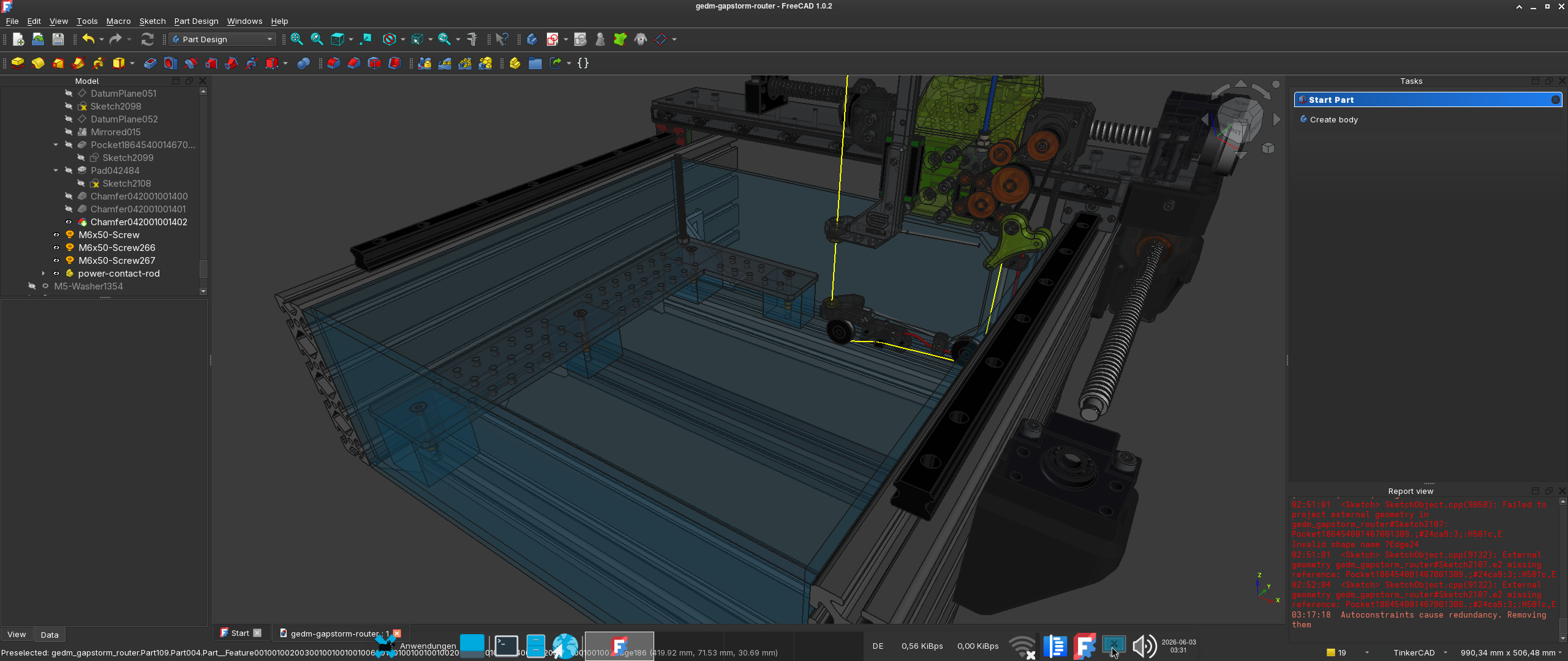
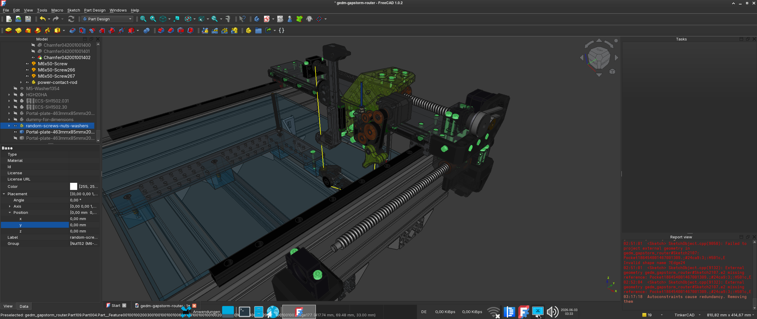
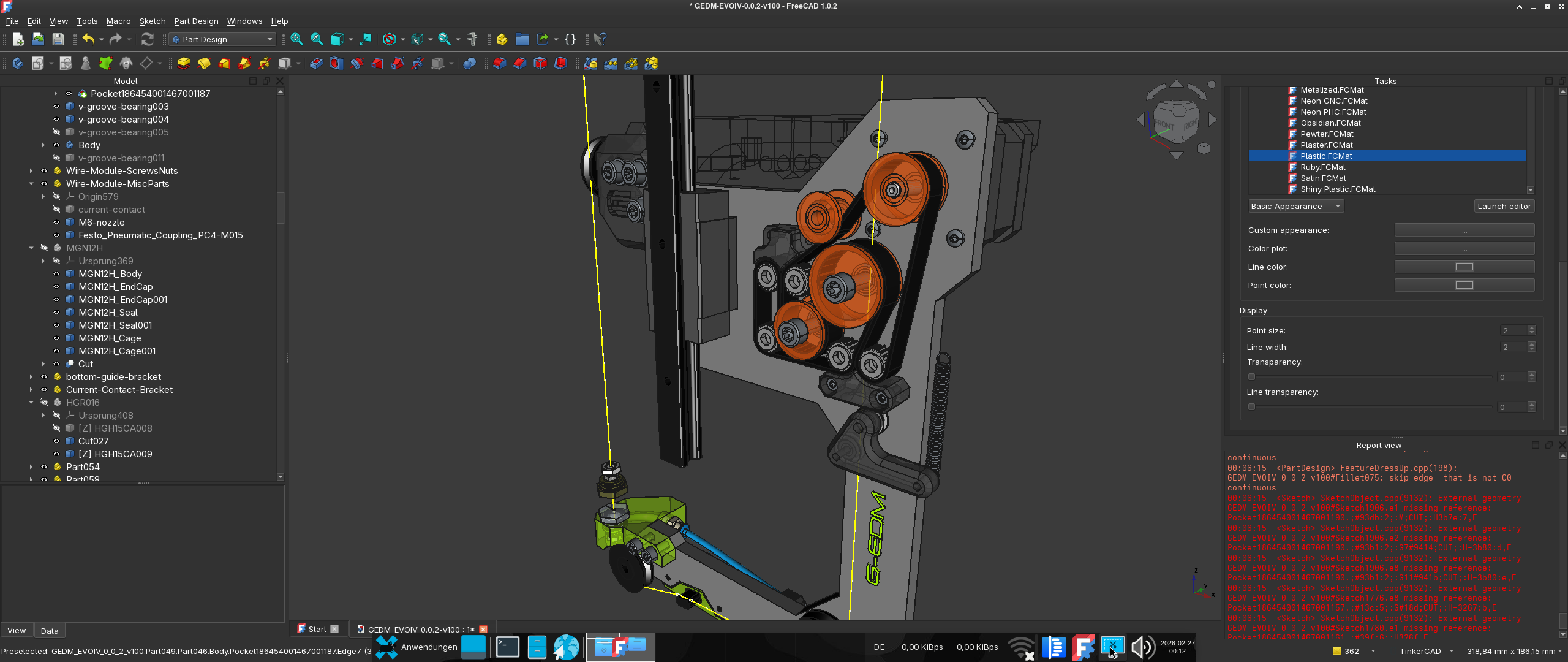
Working on the new Router design
06/03/2026 at 01:57 • 0 commentsThe next router is a lot easier to build. Some parts are cut to size to reduce weight and lower the cost factor.
Much less printed plastic, only one HGR20 rail on X, ballscrew on Y reduced to the size needed, the large Y extrusion cut to the needed size, new mounting table concept and some other changes.
The project file will provide a portal for HGH20CA blocks (the ones that ship with most HGR20 sets) but also a portal for HGH20HA linear blocks which are a little longer and better for Y.
If things work out the new C-Arc and the portal can be ordered on http://justway.com later.
Also this time all parts are labeled with sizes etc. so it is easy to lookup the required size of for example rails/ballscrew/extrusion/acrylic plates etc.
Still trying to figure out a cheaper replacement for the aluminum extrusions.
![]()
![]()
-
G-EDM Gapstorm wire module - Backbone arrived
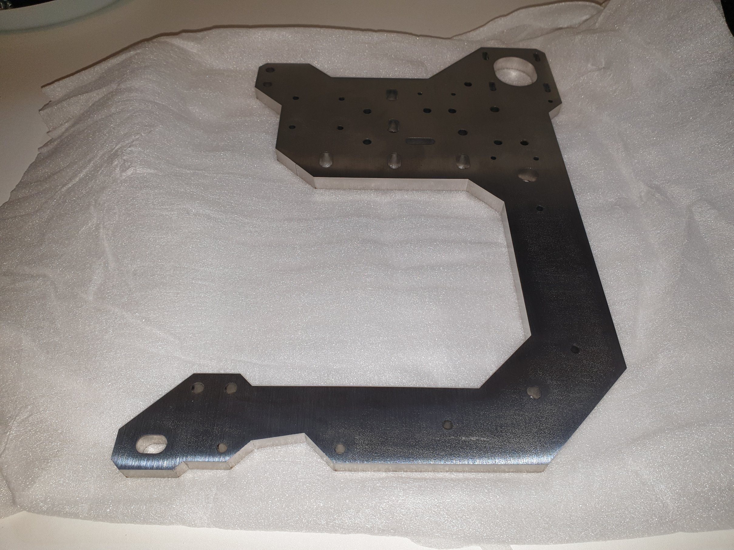
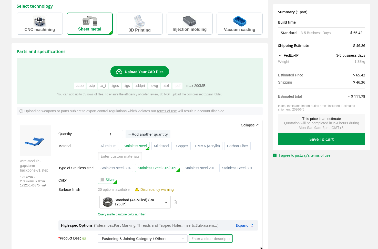
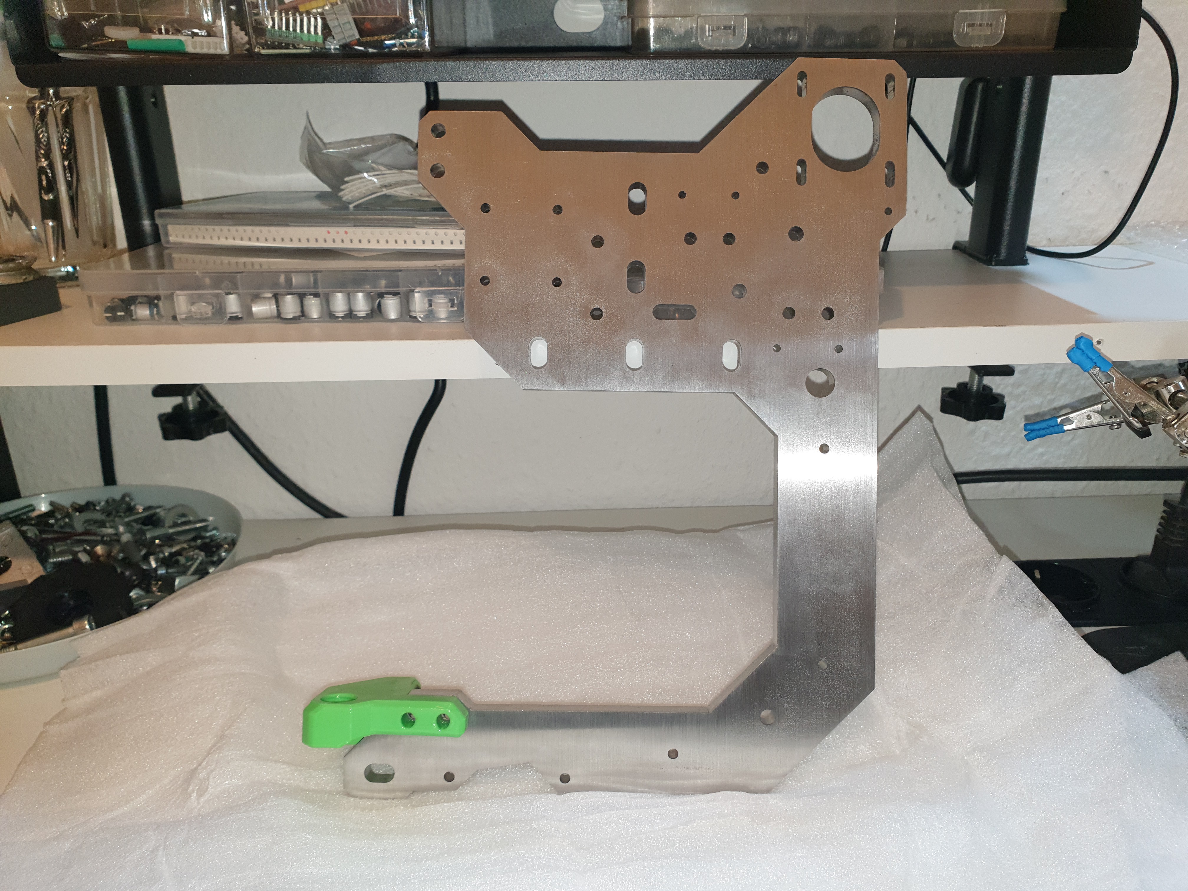
05/26/2026 at 12:59 • 0 commentsThe new wire module design is almost ready and justway.com sponsored the backbone. Ordering process is straight forward and couldn't be easier. Uploaded the step file, selected the manufacturing process (Lasercut in this case), material, surface finish and it was good to go. Big thanks to the team from justway for providing their service and helping the G-EDM project getting forward.
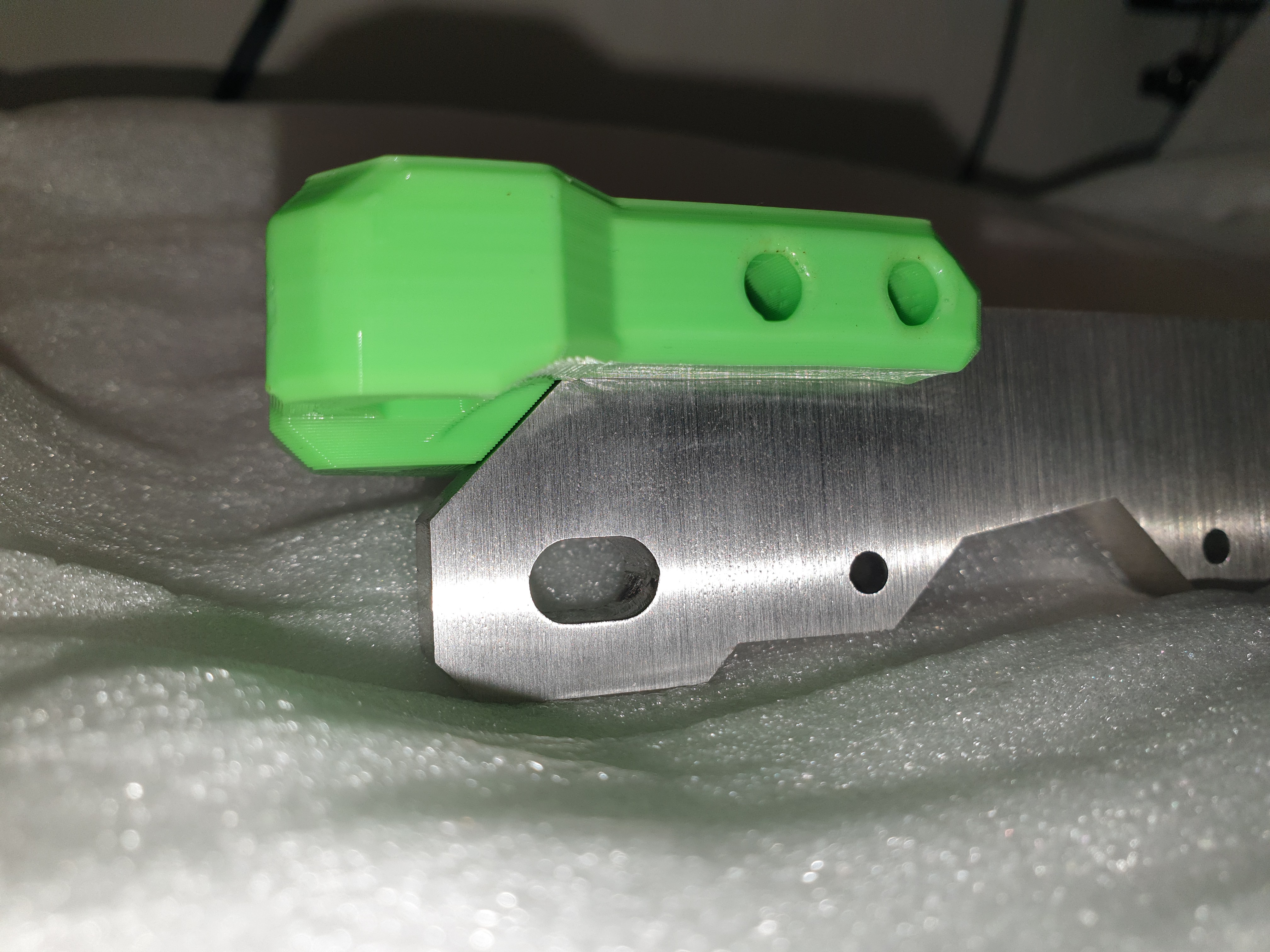
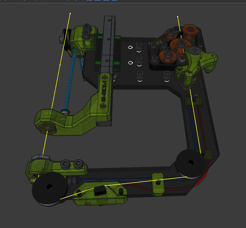
The part is laser cut from solid 8mm stainless steel. This version has a belt driven wire feeder on the C-ARC itself and requires only some minor 3D printed add-ons which heavily reduces build complexity while improving rigidity and also the maximum cutting area.
The part was packaged well and arrived without surface damages. I haven't measured the tolerances but it seems to be within the range that is expected for laser cutting. Some of the holes had a perfect fit while some others had some residues from the cutting process. Lasercutting 8mm stainless steel does not create a mirror finish. But everything was within the expected range and to specs. Nothing to complain here.
They offers multiple surface finishes and I would have loved to get the black oxide finish but to reduce the cost for the prototype I went with the standard raw finish.![]()
Ordering is straight forward: Uploading a STEP file, choosing the material, selecting the surface finish, and designating a product category for customs.
![]()
After the part passed the review process the order is ready for payment, and that's essentially all there is to it. The customer service team is friendly and readily available to assist if any help is needed, making the entire experience smooth and pleasant.
Stay tuned for the build process.
![]()
![]()
And this is how it will look:
![]()
-
Firmware to run the G-EDM Gapstorm Board
04/29/2026 at 22:10 • 0 commentsThe new firmware is available on github now. This firmware is only compatible with the gapstorm board and upgraded EVOIII boards. A tutorial showing how to upgrade the EVOIII boards will follow soon. It is not hard and can be done by everyone with a soldering iron.
-
How to Start a Sinker EDM Job on the G-EDM
04/13/2026 at 17:44 • 0 commentsHow to Start a Sinker EDM Job on the G-EDM
While many are familiar with the G-EDM's capabilities, it’s worth noting that the machine supports both wire and sinker EDM operations. Unlike wire EDM, sinker EDM does not require a GCode file; instead, it relies on the machine’s firmware to generate the necessary motion commands.
Understanding Sinker EDM Operation
Currently, sinker EDM is performed with a single axis moving in a single direction. After selecting the appropriate settings, such as cutting depth, axis, and direction, the firmware automatically generates the required GCode command.
The process begins with the selected axis performing an initial probe to establish the workpiece’s zero position. Once this is obtained, the machine moves along the axis for the specified cutting depth, calculated from the probe point.
Step-by-Step Guide to Starting a Sinker EDM Job
1. Access the User Interface
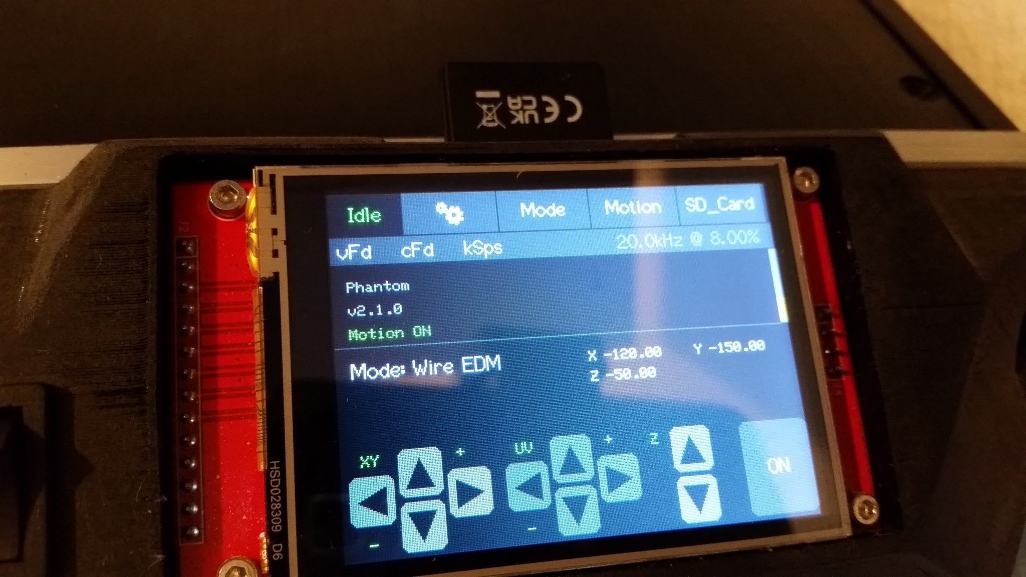
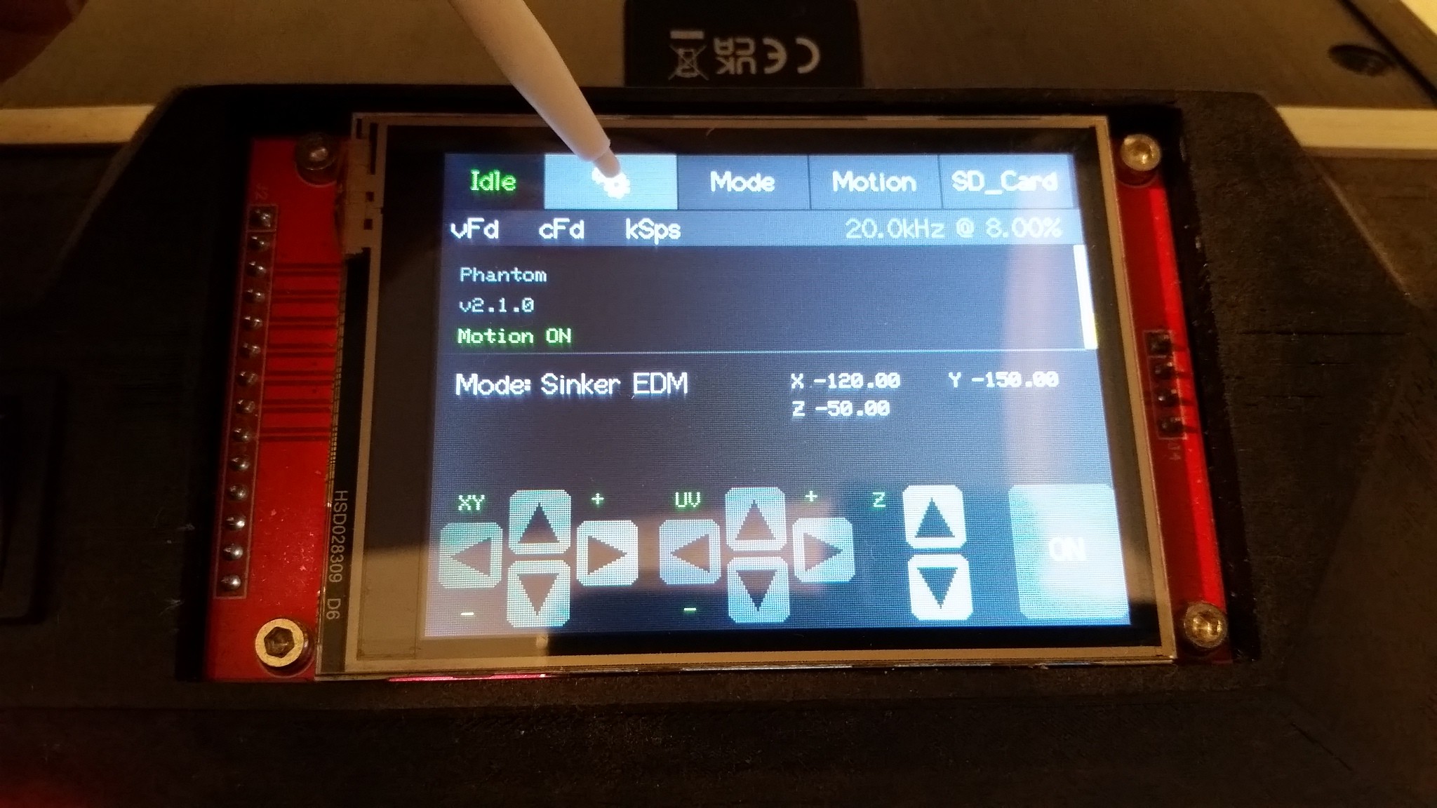
The front screen of the G-EDM user interface provides all necessary controls and settings. By default, the machine operates in wire EDM mode, so the first step is to switch to sinker mode.
![]()
2. Switch to Sinker Mode
Tap the MODE button on the touchscreen to open the mode menu.
Select "Sinker EDM" from the options. The button will highlight, indicating the active mode.
The front screen will update to reflect sinker mode. This selection is stored in the ESP memory and will persist after rebooting.![]()
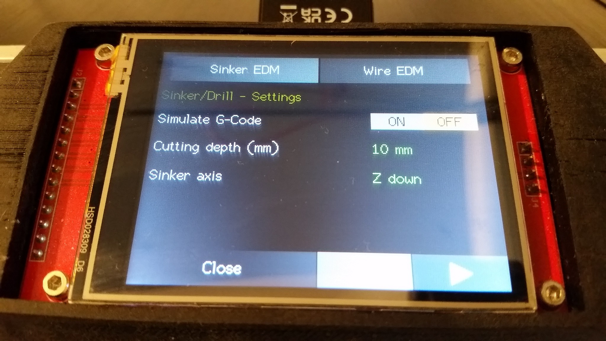
3. Set Basic ParametersCutting Depth: The default is 10 mm. Since sinker mode currently does not involve probing for the cutting depth, this value represents the total travel depth after the initial probe.
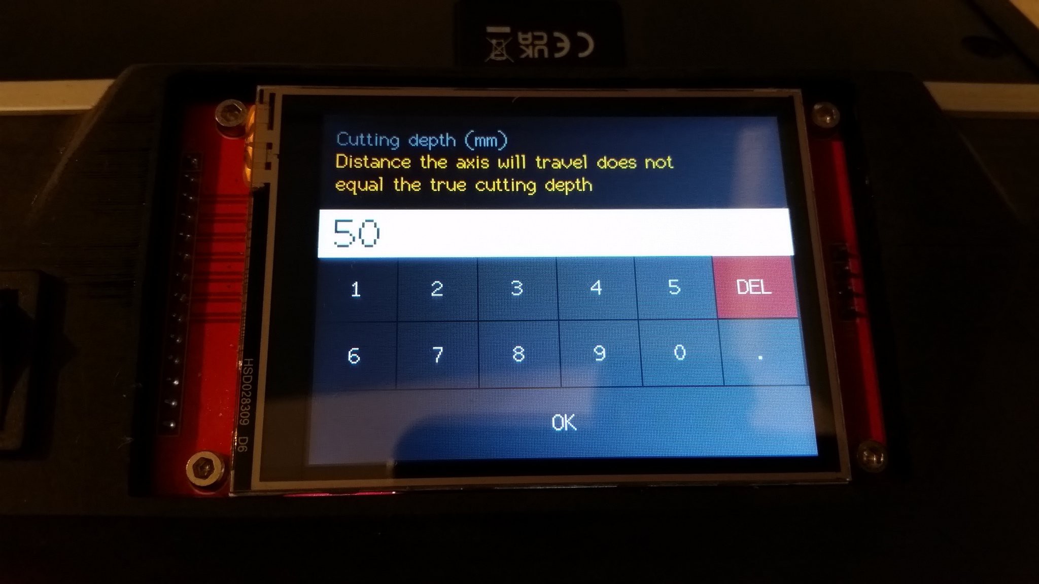
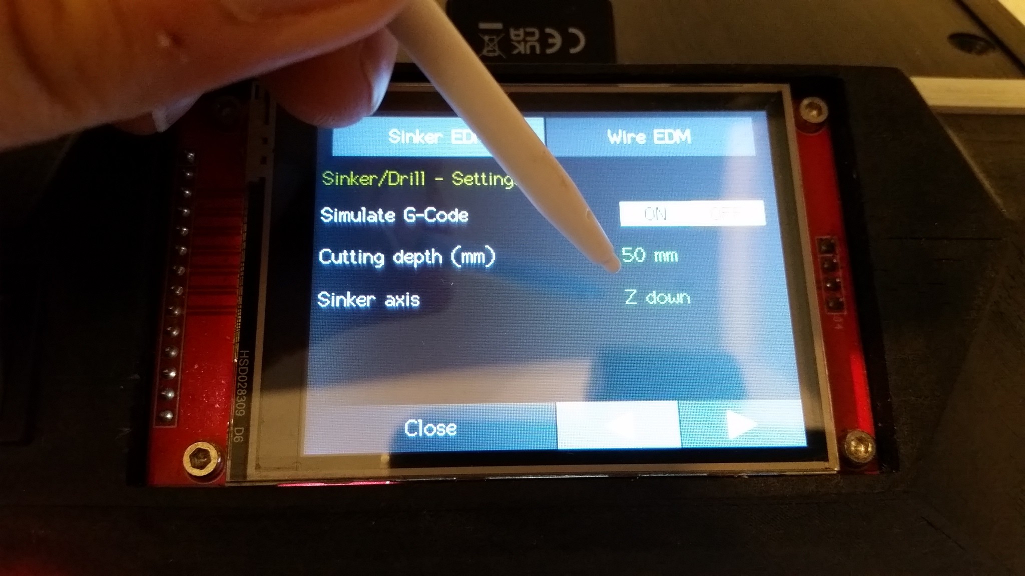
Adjust if needed: For example, set it to 50 mm for a deeper cut:- Enter the desired value.
- After the initial probe, the machine will move into the workpiece by this distance and then stop.
![]()
4. Confirm Axis Selection
Typically, sinker EDM uses the Z-axis (default). However, other axes like X or Y can also be used.
Note: If you run the XYUV or XYUVZ configuration, selecting X or Y axes for sinker operation will chain axes together (e.g., XU or YV) to run a straight line without tilting the wire.
This is the only setting that is not persistant. It will always be Z down after powering the machine on.![]()
5. Optional: Use the Wire Module for Straight Cuts
If the wire module is installed, you can perform straight-line cuts with the wire in sinker mode.
This feature allows quick, GCode-free straight cuts, which can be very useful.6. Run the Line
Close the settings menu and head back to the frontscreen. Turn the Motionswitch (On/Off rocker switch) to On to unlock the motion and press the start button on the screen at the right bottom. It will then start. Turning the motion switch off will always stop the process.
Additional Settings and Tips
Flushing and Dirt Removal
Sinker EDM creates pockets that can accumulate debris.
To maintain cutting quality, periodic flushing motions are recommended.
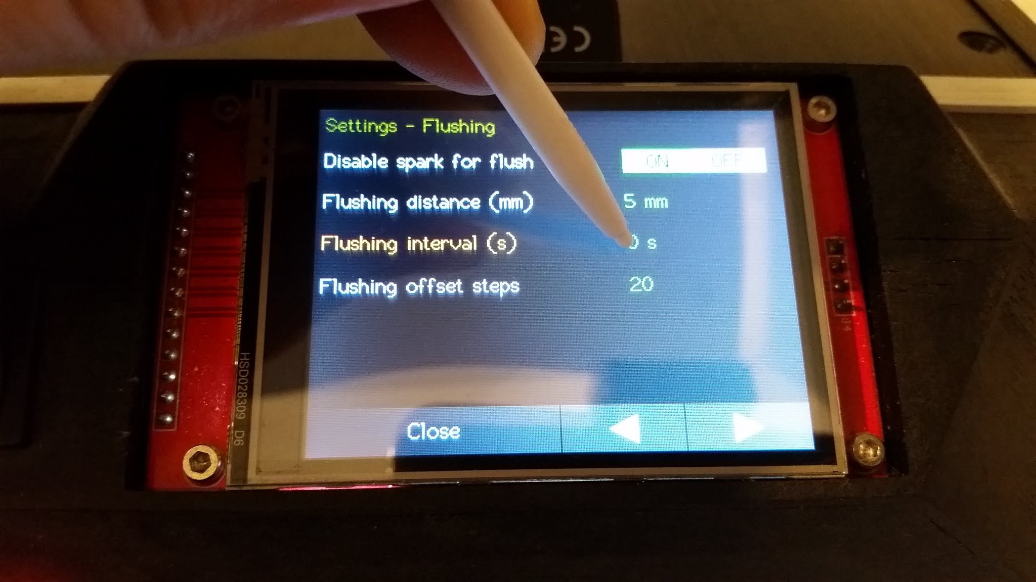
You can configure flushing intervals and travel distances in the settings menu under the Flushing section.
After each flushing retraction, the machine returns to the initial position, offset by a configurable number of motor steps (offset steps) to prevent collisions while returning.Configuring Flushing:
- Interval: Set how often the flushing motion occurs (e.g., every 2 seconds).
- Distance: How far the axis moves during flushing.
- Disabling Flushing: Set interval to zero to disable this feature.
The flushing settings are in the settings menu:
![]()
![]()
Summary
- Switch to sinker mode via the Mode menu.
- Set your desired cutting depth.
- Ensure the correct axis is selected.
- Adjust flushing settings if necessary.
- Proceed with probing and cutting as usual.
-
G-EDM gapstorm shared on PCBway
04/11/2026 at 16:45 • 0 commentsThe Gapstorms PCBs are now available on PCBway (project is still in the review process and maybe it takes some days to unlock) Have fun building and cutting.
https://www.pcbway.com/project/shareproject/G_EDM_Gapstorm_Pulseboard_14dd4341.html
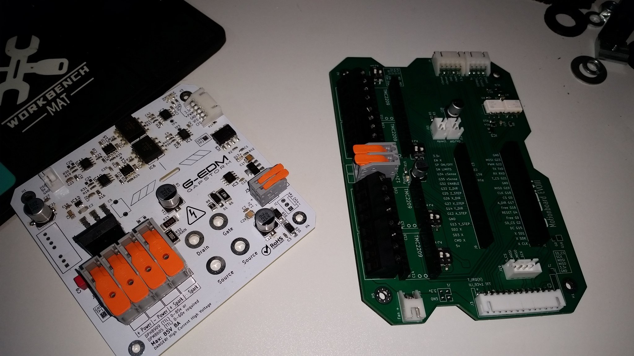
Key Improvements compared to the EVOIII Board:
- Compact Size:
PCB footprint reduced to only 99mm x 99mm.
- Simplified Manufacturing:
Some through-hole (THT) components replaced with surface-mount (SMD) versions for easier assembly.
Integrated Current Shunt:
- The current shunt resistor is now onboard, reducing wiring complexity.
- Upgraded Op-Amps:
Replaced LM358 with OPA350 for improved performance.
- Advanced Gap Proximity Sensing:
Features two sensing channels: one for current feedback and one for voltage.
Unlike EVOIII, which connected voltage sensing to the power bus and detected only hard shorts via voltage drops, Gapstorm’s voltage sensing provides fast, linear, real gap proximity detection.
Requires firmware update to utilize this feature.
The PCB includes a footprint for converting between gap proximity sensing and bus voltage sensing by unsoldering and repositioning a resistor.
Wiring and Calibration Enhancements:
- The onboard shunt resistor simplifies wiring, eliminating the need for an external shunt wire.
- Uses a fixed voltage divider for voltage feedback, removing the need for calibration potentiometers and making setup plug-and-play.
Power Mosfet Improvements:
- Replaces four parallel IRFP260N Mosfets with a single, screw-mounted SOT-227 package.
- The new Mosfet's package is electrically isolated from the drain, allowing direct mounting onto the metal enclosure, which acts as a large heatsink.
- No soldering needed; just screw the Mosfet onto the enclosure with a touch of cooling paste recommended.
- This design simplifies assembly and enhances thermal management.
Adjustable frequency range up to 100khz is supported by the firmware. In theory the firmware has no problem providing 200khz but it makes no sense and pollutes the CPU too much as there is an interrupt on the rising edge to trigger the readout of the ADC samples. It does skip if there is already a readout triggered but it still is extra load and from what I have seen there is just no need at all for higher frequencies.
The "new thing" as of 11.April.2026 is the Gapstorm pulseboard together with the EVOIII Motionboard.
![]()
![]()
-
The next firmware version - What can you expect
04/02/2026 at 05:34 • 0 commentsWhile time passes by and work increases things keep developing in the background in all directions and a new firmware will drop soon.
What are the major changes?
Of course a lot of bugs where fixed. As always. One issues was a deadlock if a user changed a setting while PWM was running at the same time. This can not happen in the process itself as PWM is always turned of first before it opens the settings menu. But outside the process while playing with the PWM and then opening the settings menu can sometimes freeze the UI.
This happens due to the high speed of the sampler that is triggered with a pulse edge. The locking mechanism had a vTaskDelay(1) to wait and in some situations the timings just prevented it from every getting the lock.
This is fixed in the next version.
The major change is the voltage feedback. The new Gapstorm Pulseboard provides gap proximity sensing and therefore is much closer to the spark then the previous boards which opens a lot of new ways to manage the cutting process.
A lot of the settings are gone and many parts of the adjusting is done by the firmware now in an adaptive way to adjusts itself to changing cutting/water conditions. A previous issue was that an electrode that plunged into the metal at some point created a feedback that almost looked like the initial feedback the deeper the electrode gets. The average current keeps rising and at some point the motion would just stop until the user adjust the setpoints.This adjustments is now done by the firmware. It captures ideal conditions and uses those to adjust if needed.
There are a lot of conditions bound to that in the background but those don't require user interactions.
The initial tests showed much finer finishes and as soon as I'm back in operational mode (have to get some things done) the full bundle containing the BOM/Gerber and schematics for the Gapstorm board, the firmware and also a tutorial about how to upgrade the existing EVO boards to the new voltage sensing.
G-EDM boards develop in a natural way step by step. Even if the new board looks very different the core circuit remained almost the same and the changes are mostly a much smaller PCB, smaller components and nicer Terminals. And of course an integrated Shunt resistor instead of the external one that is used by the EVO boards.
Upgrading the EVO boards does not require much experience and can be done by every user with a soldering iron. After those changes they will behave the same as the Gapstorms.
I will ensure that nobody is left behind.
-
Powercore? Never heard of her.
04/01/2026 at 03:16 • 0 commentsPeople keep contacting me asking how the G-EDM compares against the PowerCore from Rack Robotics.
I'm sorry to be the one telling them, but you can't compare those concepts. I haven't seen any valid cuts made by users from a PowerCore at all. It does not provide a motion control firmware and even worse the v2 AND the v3 seem to have a design issue.
Many v2 users reported issues with their devices getting defective. This flaw was so significant that they made the v3. Now people with a PowerCore v3 show up reporting defective devices too.Please don't come at me asking how it compares against that. G-EDM users measure cutting speed in mm/min and not in arcgenerators/mm.
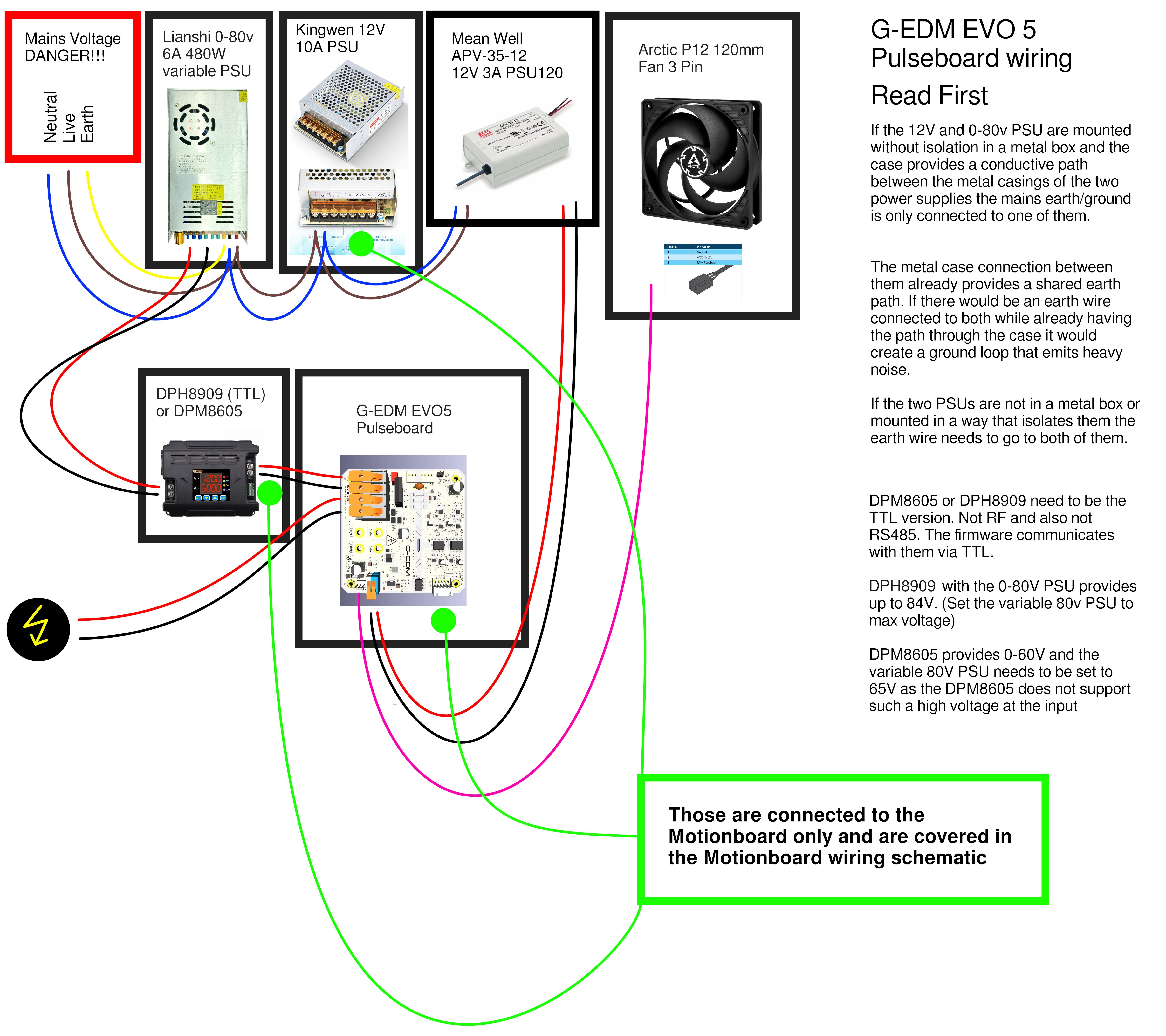
G-EDM is a working design with prove-of-work by multiple different people and not a single failure of the electronics since the early days. It is possible to destroy the Pulseboard by using an unregulated PSU as input but the docs clearly say to run it with a DPM/DPH which the boards are designed for. Userfaults are not G-EDM faults.
I would buy a PowerCore once at least v5 or v6 is available. But with the G-EDM at half the pricetag and triple the features there is no reason for it.
Hope this clarifies that question as I'm not willing to dive deeper into this topic.
-
Website up and running
03/20/2026 at 23:14 • 0 commentsDocumentation, build logs and more updates will be available on the website. Currently only available in German. English language set should be available in 1-2 weeks.
Overview:
Updates will be published on the user profile:
-
New C-Arc for the EVO Router
02/26/2026 at 23:25 • 0 commentsHobby wire EDM has come a long way and developement happens rapid. New PCBs, new hardware, lots of progress.
A little preview of the next version of the G-EDM EVO router. A C-Arc type wire module with stainless steel backbone, belt driven wire feeder integrated in a compact size on the arc itself and a new spool holder for 5kg spools with integrated Nema17 is also waiting for some tests.
![]()
![]()
-
Cutting 50mm steel with a DIY wire EDM machine
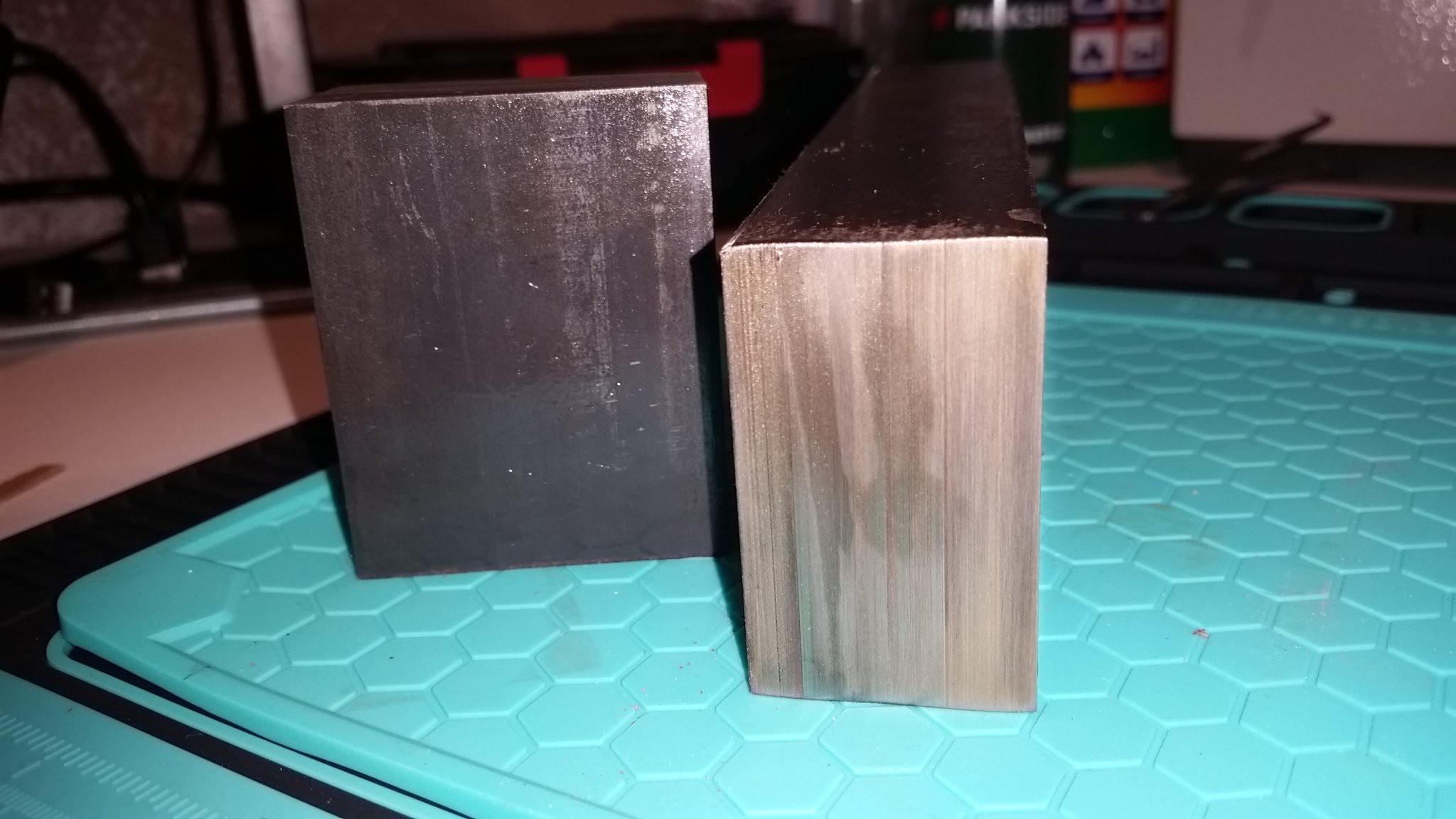
12/12/2025 at 23:09 • 0 commentsNever thought this would be possible but it did the cut through 50mm steel.
![]()
G-EDM
The G-EDM is an electrical discharge machine that supports sinker EDM, EDM engraving, EDM drilling and Wire EDM operations. #Drahterodieren