 John Rampelt
-
11Build CHRP4 into a robot
Follow these instructions to build a simple and inexpensive robot platform made from hardware store components, or attach your tested CHRP4 to the robot platform of your choice. The line and floor sensing components work well when mounted approximately 1/4" (6mm) from the floor, and when they are optically isolated from one another. This is accomplished by drilling silos into the MDF base of the simple robot platform, or can be done by encasing the IR LED in a short length of black heat shrink tubing in other builds.
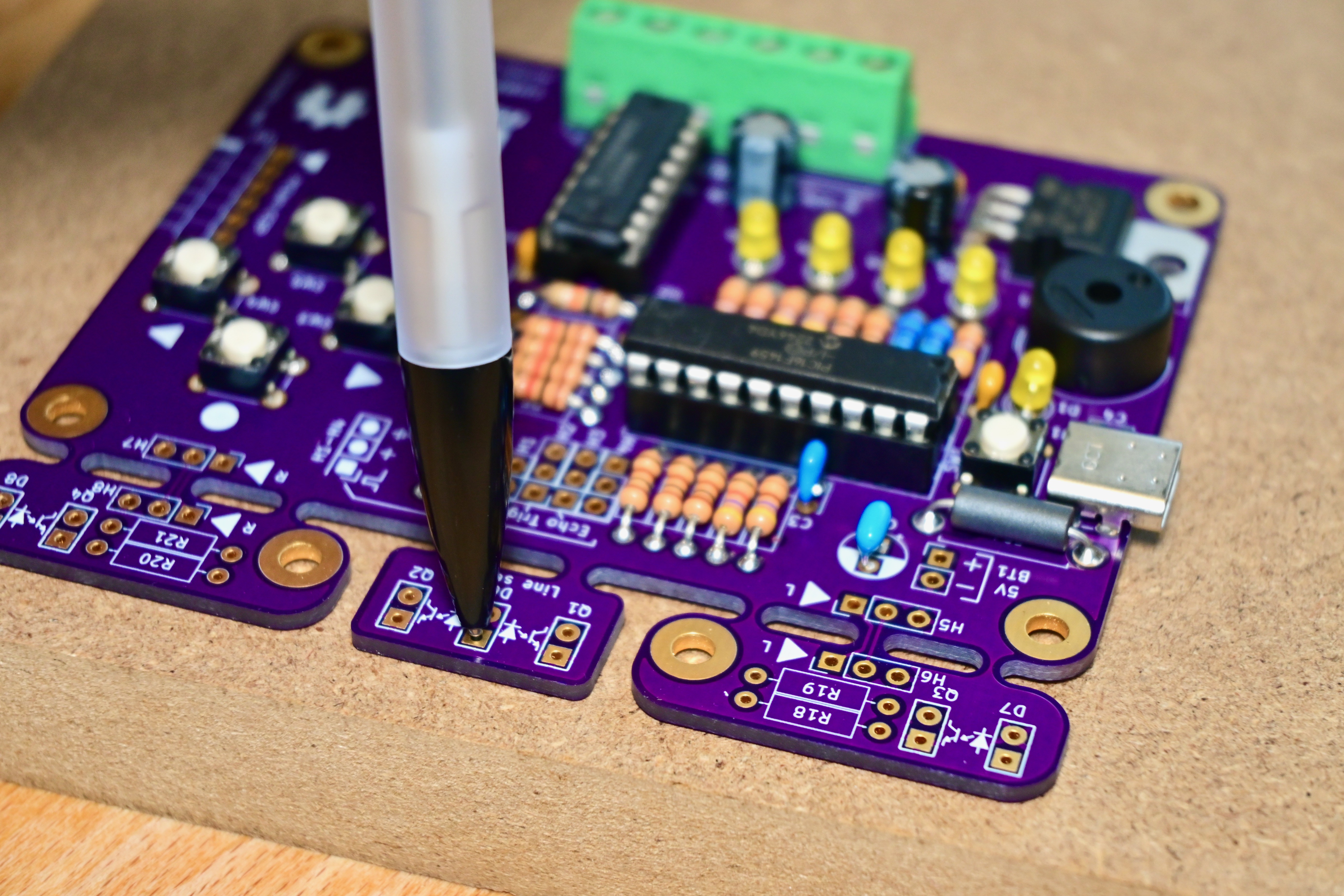
This next set of steps demonstrates an easy way to mount the line sensors in the simple robot platform. Start by setting CHRP4 in its place on the robot platform and marking the location of its four mounting holes. Using a 0.5mm mechanical pencil, insert the pencil lead through each of the pads for D6, Q1, and Q2 and twirl the pencil to mark the location of each of the part leads on the platform.
![]()
-
12Connect the dots and drill the holes
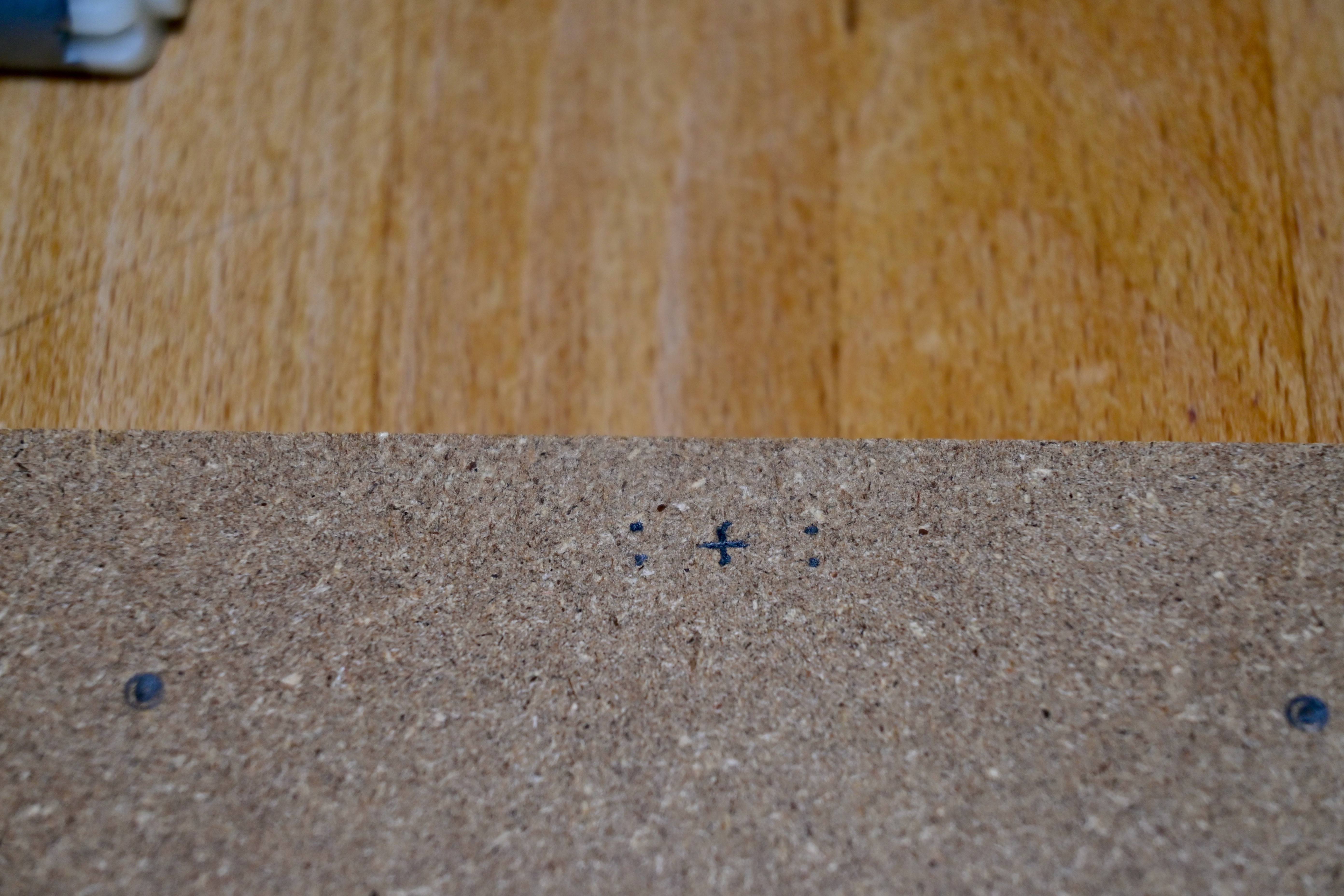
Connect the dots representing the location of each pair of optical component leads, and mark the middle of the line between the two lead holes. The centre of D6 has been marked with a cross in the photo below, and the phototransistor lead locations and two round PCB mounting hole marks are also visible:
![]()
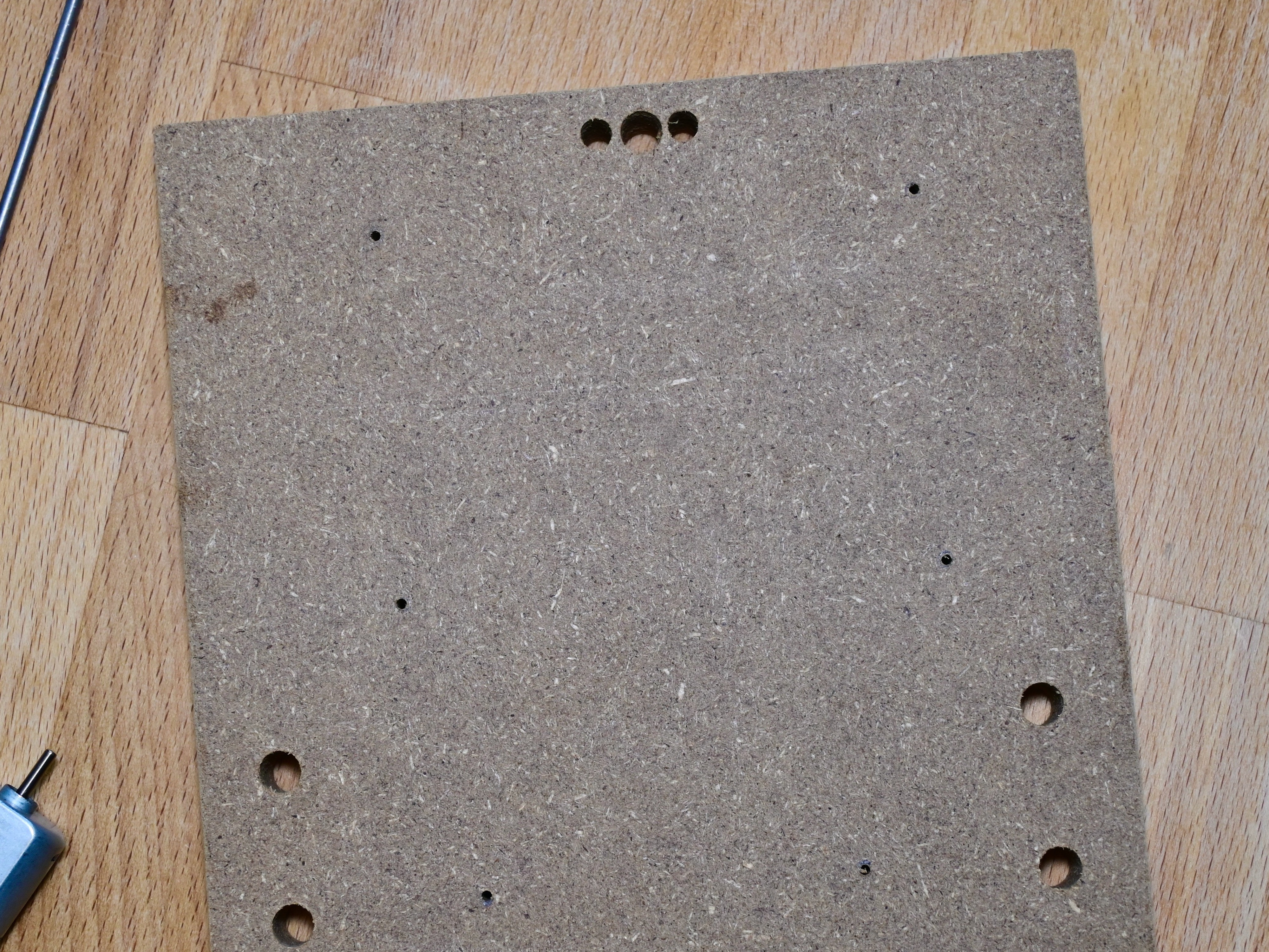
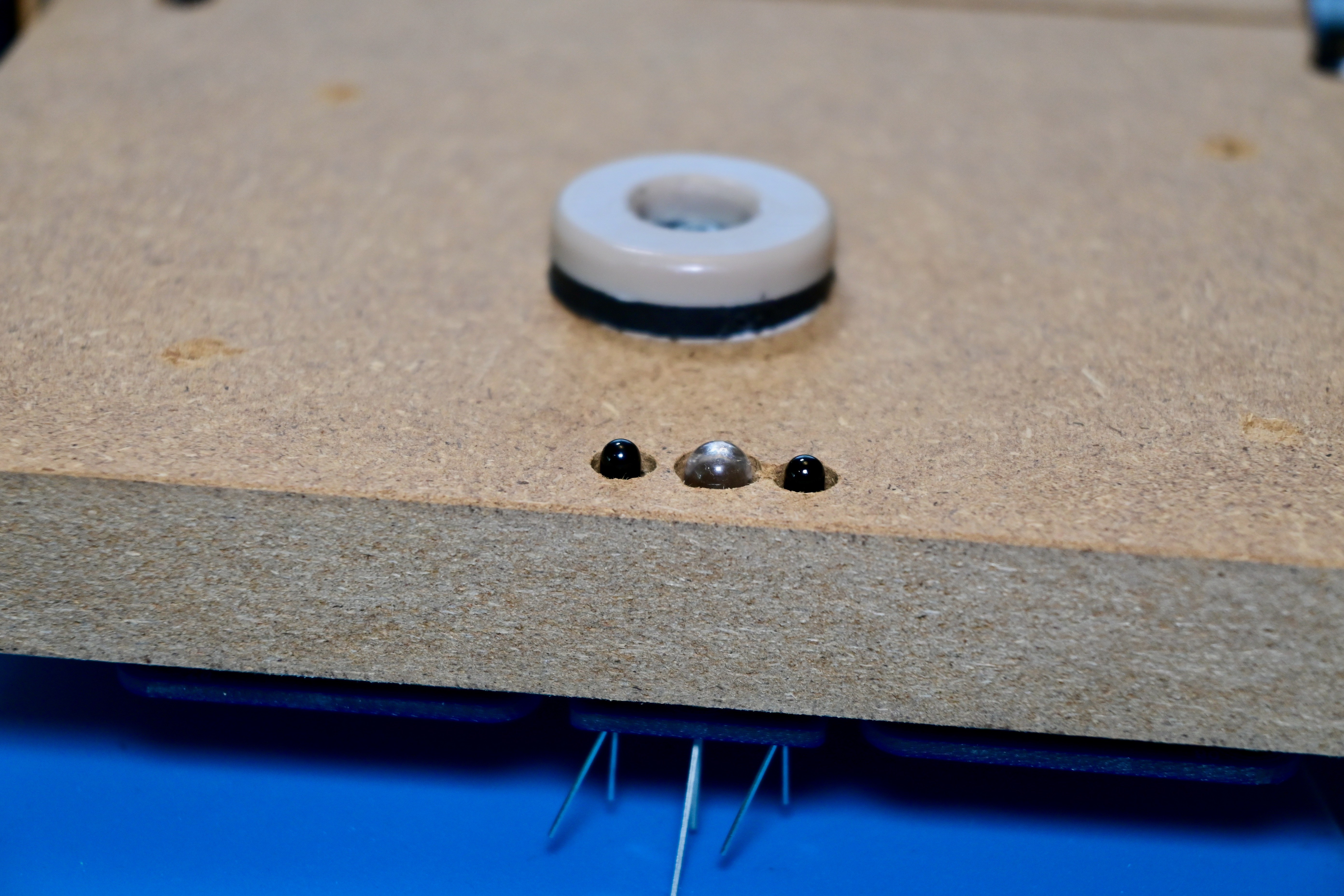
Drill the holes for each of the optical components centred on the mark you made between the lead marks. Drill the hole for the central 5mm IR LED (D6) using a 1/4" drill bit. Next, carefully drill the holes for the 3mm phototransistors (Q1 and Q2) using a 3/16" drill bit, leaving about 1mm of wall between the component silos.
![]()
If using an MDF platform, drill the PCB and battery pack mounting holes using a 1/16" drill bit (to use #4 wood screws), and drill the motor mounting holes using a 1/4" drill bit.
-
13Mount CHRP4 and install the line sensor LED
Mount CHRP4 to your robot platform by either screwing it to the platform directly or by using small spacers or washers to raise it slightly. If mounting CHRP4 directly, turn the screws just until they touch the board – do not over-tighten or you will bend the board and risk breaking traces or your solder connections!
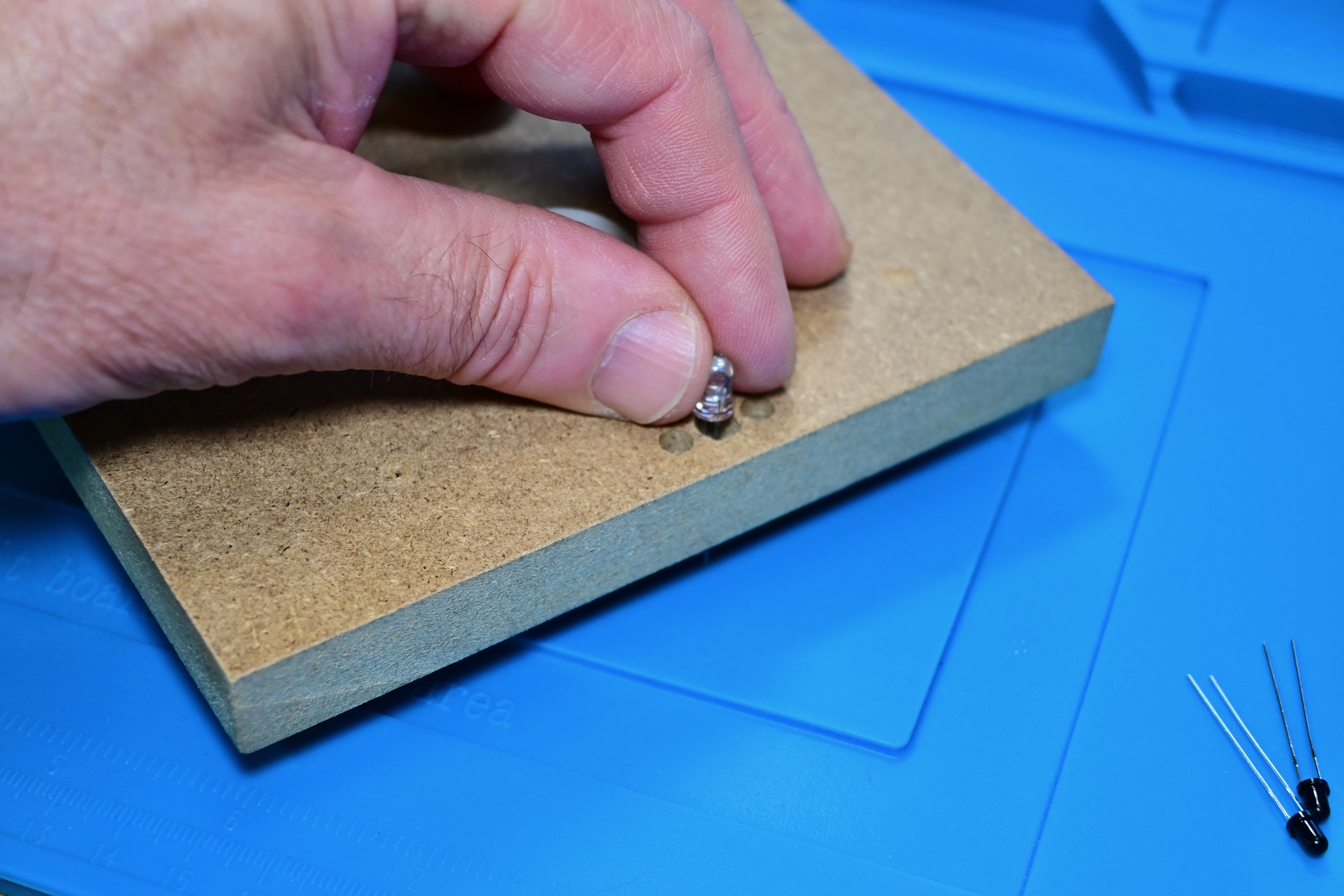
Insert the floor LED through the bottom of the platform and align its leads with D6 on the CHRP4 circuit board. LEDs are polarized – ensure that you insert the longer lead of D6 into the square pad on the CHRP4 board, and the shorter lead into the round pad.
![]()
For the simple robot build, set the height of the LED so that approximately 1mm of the LED is sticking out over the surface of the platform. Then, carefully solder the D6 LED leads on the top of the circuit board.
![]()
-
14Install the line sensor phototransistors
Install the phototransistors the same way as the LED. Insert the longer lead of each phototransistor into the square pads of Q1 and Q2, and the shorter lead into the round pad. (The anode and cathode pins of each floor sensor LED are graphically marked on the CHRP4 silkscreen, as are the collector and emitter pins of each phototransistor).
Align the tops of the phototransistors so that about 1mm of their round lenses extends past the platform and solder their leads on the top of the CHRP4 circuit.
![]()
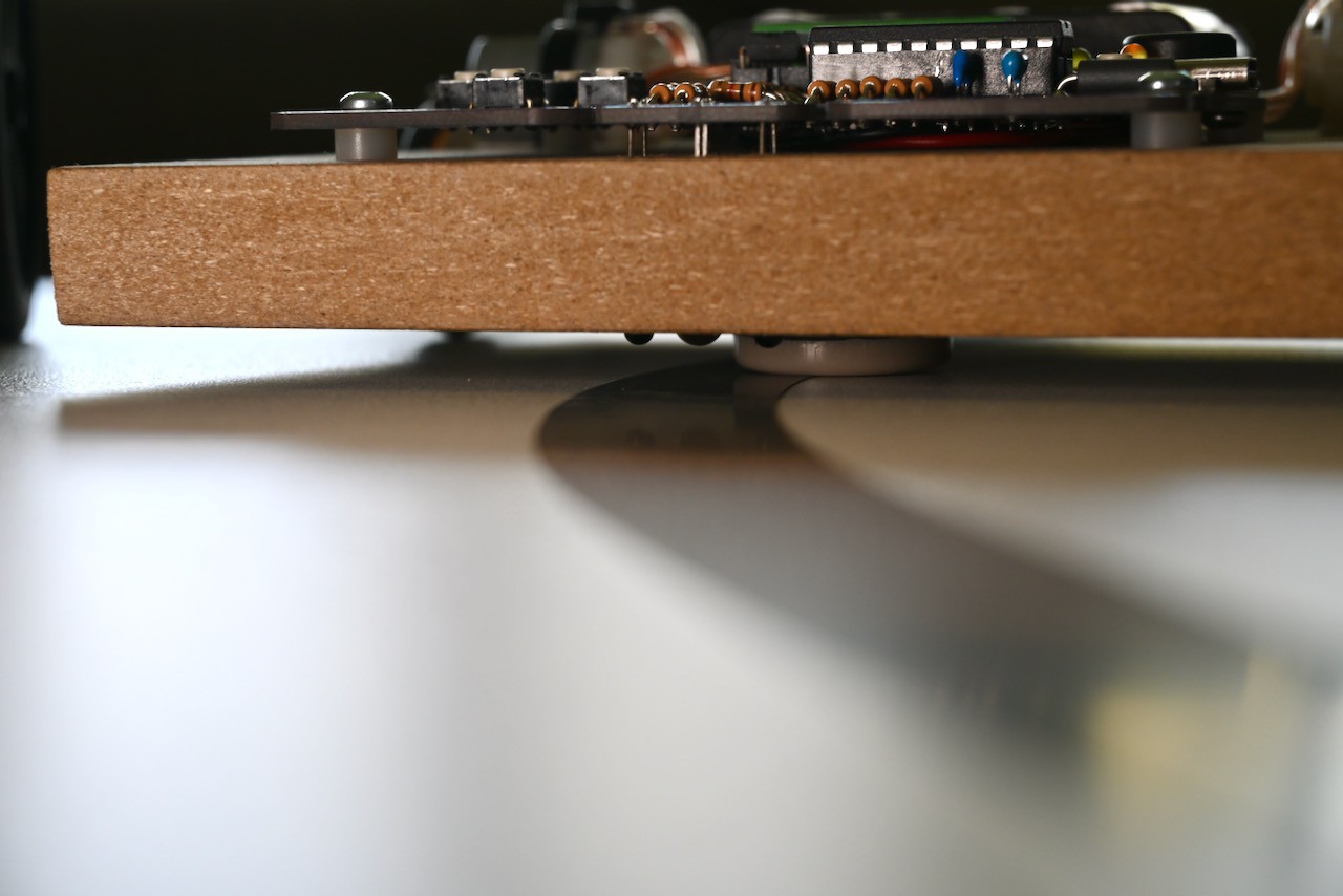
The chair glide on the simple robot platform set the proper height of the sensors from the floor, and the small wood walls between the LED and phototransistor silos optically isolates the components. (If you mount your CHRP4 to a thinner platform, a short piece of heat shrink tubing around the LED should be enough toisolate its light from spilling to the side and affecting the phototransistors.)
![]()
-
15Finish your robot by installing the battery and motor wiring
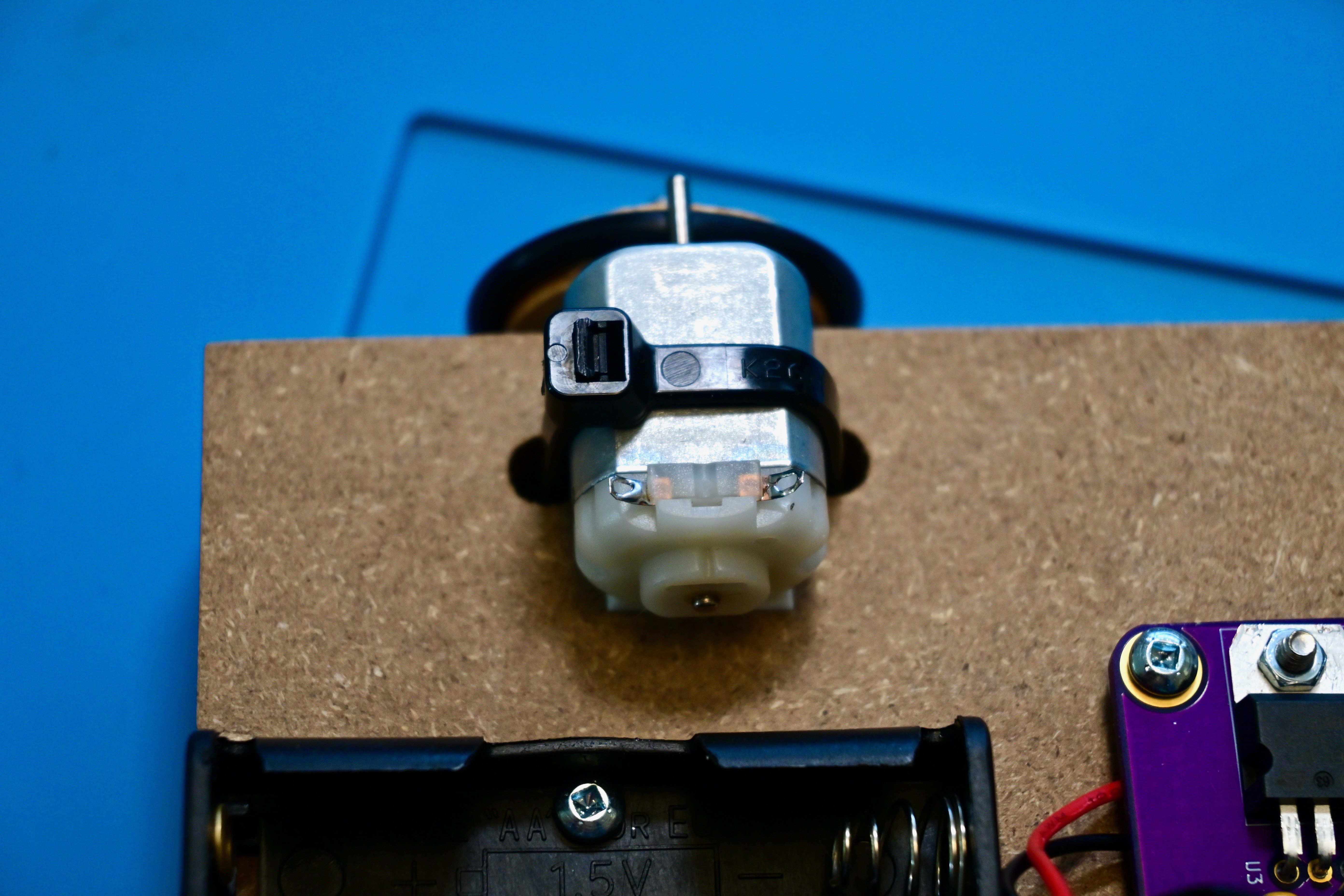
Strip and tin the ends of the battery pack wires, and four short lengths of 20-24 gauge stranded wire for the motors (we used 22 gauge for this build). Carefully bend the motor terminals away from the plastic end-cap of the motor and tin them while applying as little heat as possible to prevent damage to the motor.
![]()
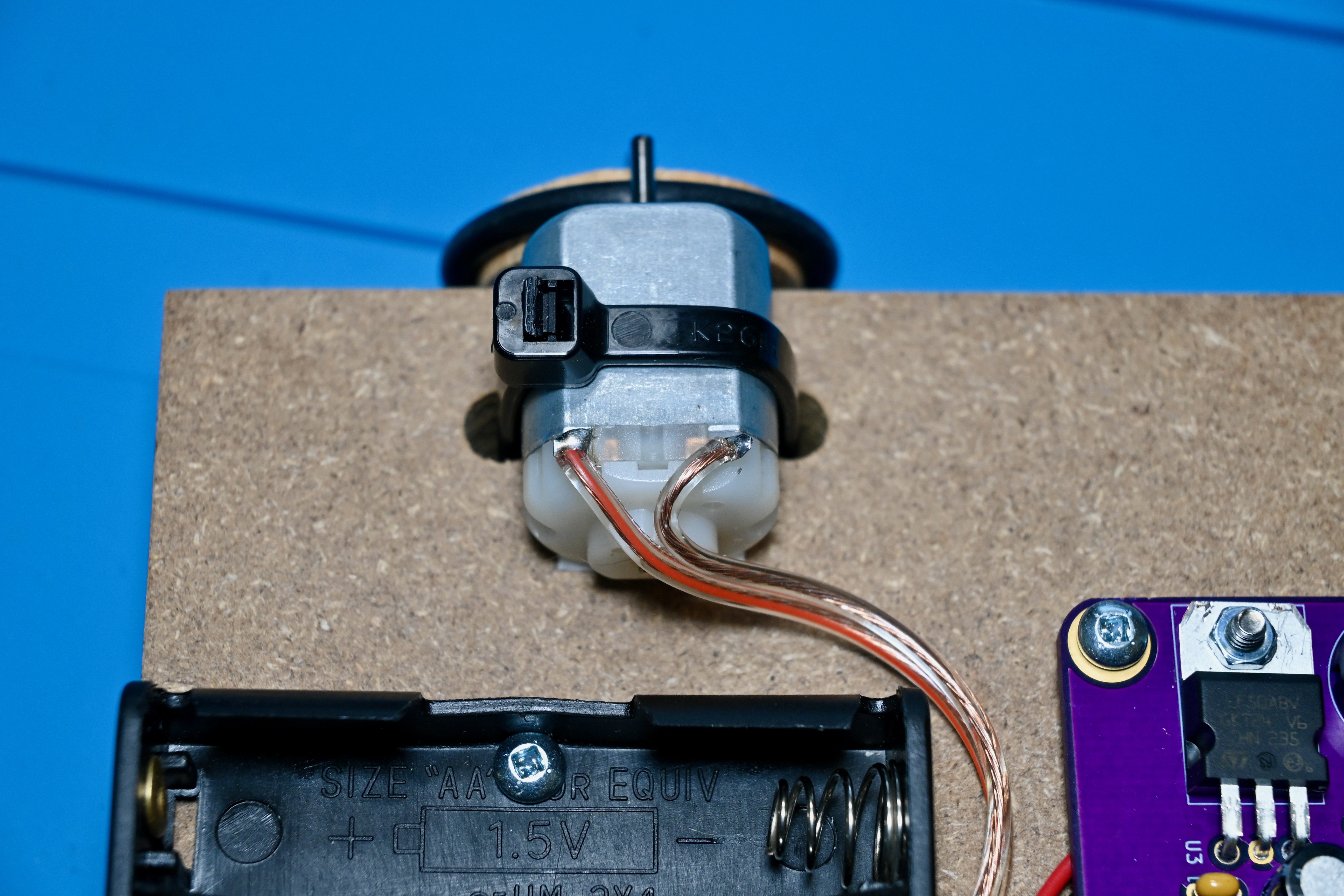
Solder the pre-tinned motor wires to the motor terminals (cut the bare wire short enough to ensure that the wire insulation goes right to the motor terminal and the wire ends don't touch the metal motor case to prevent accidental short-circuits!).
![]()
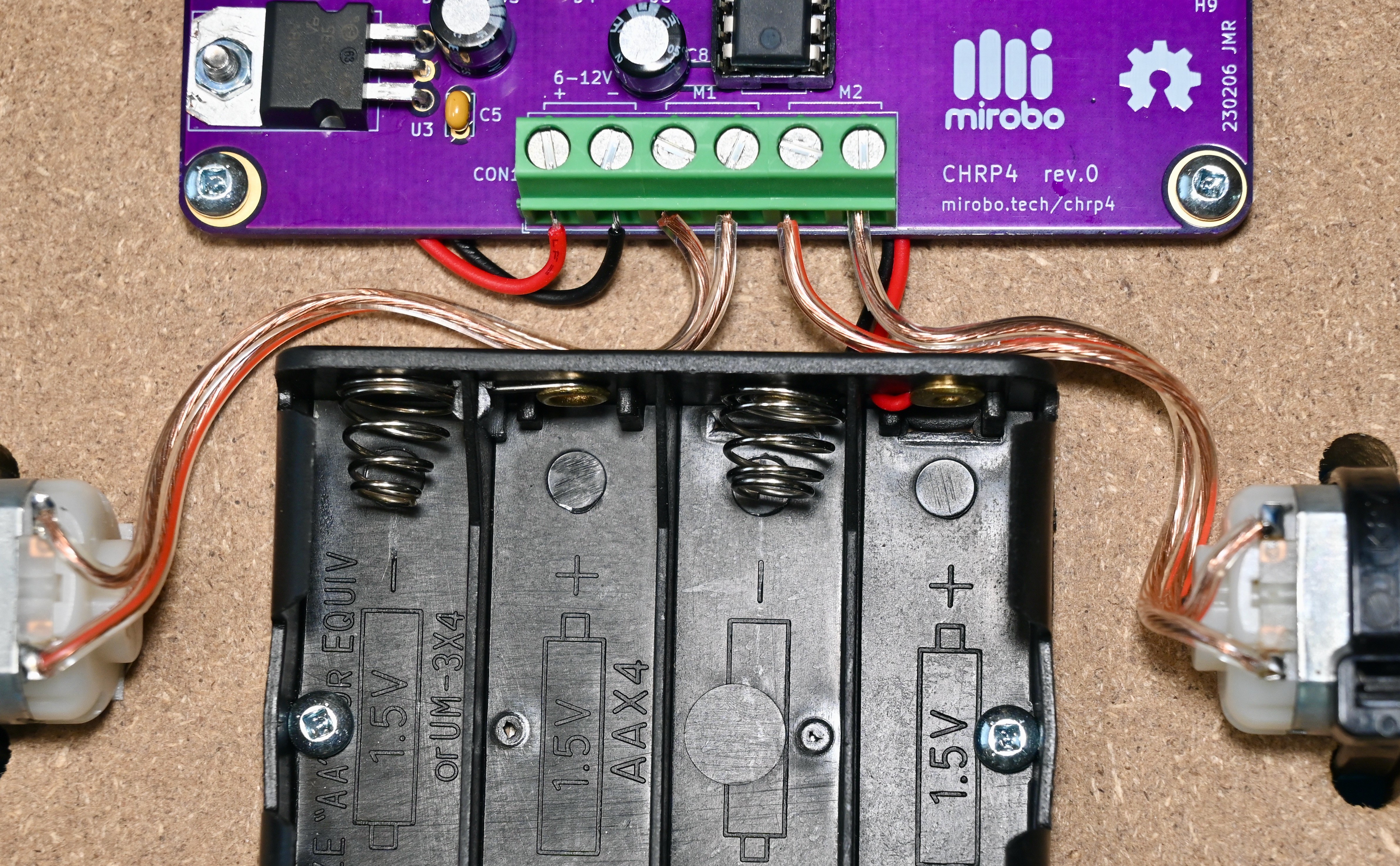
Connect the battery pack and motor wires to the CHRP4 screw terminal strip in this order (from left to right): battery plus (red) wire, battery minus (black) wire, the two left motor wires, and the two right motor wires. The order of the motor wires will affect which direction the motor turns, but this can be reversed later by either switching the wire positions, or by changing the commands in your program.
![]()
That's it! Follow the steps in the introductory programming activities to learn how to program your CHRP4 and turn it into a line-following robot.
CHRP4 USB robotics development board
A simple, inexpensive development board for learning or teaching beginner microcontroller programming and robotics.

Discussions
Become a Hackaday.io Member
Create an account to leave a comment. Already have an account? Log In.