 John Rampelt
-
1Determine your CHRP4 configuration and gather the parts for your build
CHRP4 can be built in three major configurations:
- Educational starter configuration – a beginner USB-C microcontroller development board with on-board pushbuttons, LEDs, and a piezo beeper. Learners can complete all of the introductory learning activities with this minimal parts, low-cost build.
- Line-following robot configuration – all of the components in the educational starter configuration plus a low-dropout voltage regulator, quad half-bridge motor driver, a screw terminal strip, an IR LED, and two phototransistors. This configuration is ideal for building a simple line-following robot, especially when paired with my simple robot platform design.
- Advanced robot configuration – all of the components in the line-following configuration plus dual IR LED and phototransistor floor sensors on break-away mini PCBs, a 4-pin header socket for an HC-SR04 ultrasonic distance sensor module, and an optional IR demodulator for remote control applications. This configuration makes it easy for beginners to build obstacle sensing robots, Sumo robots, and remote-controlled robots.
Use the schematic diagram to determine which components are needed for the CHRP4 configuration you would like to build. The parts needed to build either of the robot configurations are labelled as optional and are shown within dashed boxes on the schematic.
Most of the parts will be commonly available from electronic supply shops, but refer to the Digi-Key parts list for components that have been selected to work the best (e.g. high brightness IR LEDs and matching phototransistors).
Any configuration can be upgraded to the next higher configuration, but the use of dual floor sensors in the advanced configurations requires the line sensor module to be broken off (or the component leads cut) as it shares I/O lines with the left and right floor sensors.
-
2Solder the resistors and USB-C connector
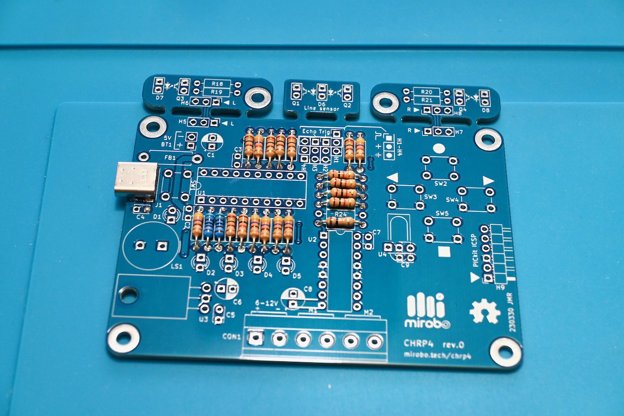
The easiest way to start assembling the CHRP4 circuit board is to install the lowest/smallest parts first, and progress to the higher, taller parts as you go. Begin with the resistors and USB-C connector.
Solder the resistors using a small conical tip soldering iron and electronic solder. Pre-bend the resistor leads, and find each resistor's location on the PCB by cross-referencing its value to its part number on the schematic. If you're new to soldering, this Soldering is Easy comic has some great soldering tips!
After getting some practice soldering the resistors, carefully solder the USB-C connector by 'drag soldering' using a flat blade soldering iron tip. See the video below for a demonstration of how to do it:
This CHRP4 build is going to become a line-following robot and has almost all of the resistors added to the main part of the board. It leaves the resistors for the break-away floor sensor modules unpopulated, as well as an isolation resistor for the IR demodulator.
![]()
-
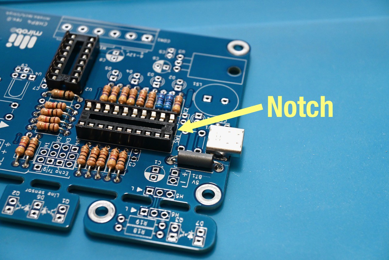
3Solder the IC sockets and ferrite inductor
Align the notch molded into each IC socket with the painted notch on the CHRP4 PCB silkscreen and insert one socket at a time into the printed circuit board. Solder one pin on each side of the first socket to keep it in place, and then check the socket to see if it is installed straight or needs adjustment before soldering the rest of the pins. Repeat the same steps for the second IC socket.
Bend the leads on the ferrite inductor (it's an un-marked grey cylinder) and install it into the circuit board the same way you did for the resistors. Its orientation does not matter.
![]()
-
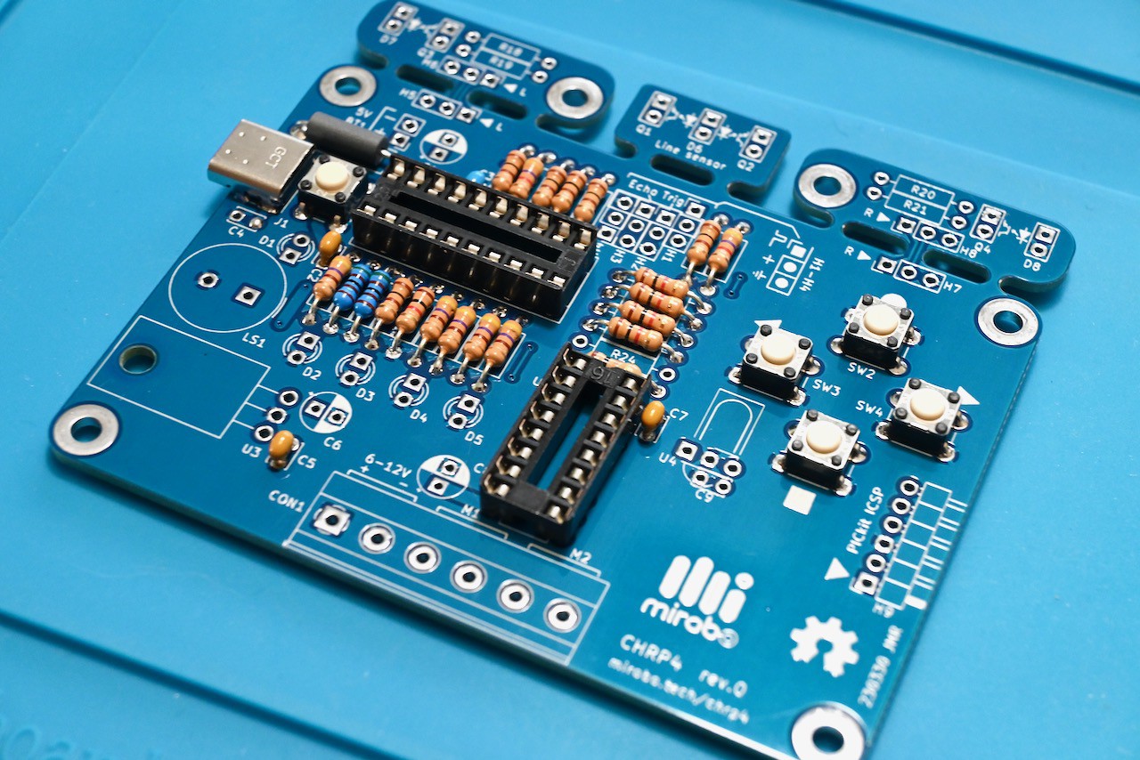
4Install the ceramic capacitors and pushbuttons
Install the small ceramic monolithic capacitors first. The orientation of these ceramic capacitors does not matter. They are coded with a numeric code that reads like resistor colour code, but in pico-farads (pF):
- 104 = 100 000 pF, labelled as 100 nF on the schematic (more commonly referred to as 0.1 µF in the U.S.A.)
- 474 = 470 000 pF, labelled as 470 nF on the schematic (or 0.47 µF in the U.S.A.)
- 105 = 1 000 000 pF, labelled as 1 µF on the schematic (but more likely to be a 1 µf electrolytic capacitor instead of a ceramic monolithic capacitor in the kit – but either works)
Install the pushbuttons by pushing their legs all the way into the circuit board pads until their bodies rest directly on the PCB, and then solder them into place.
![]()
-
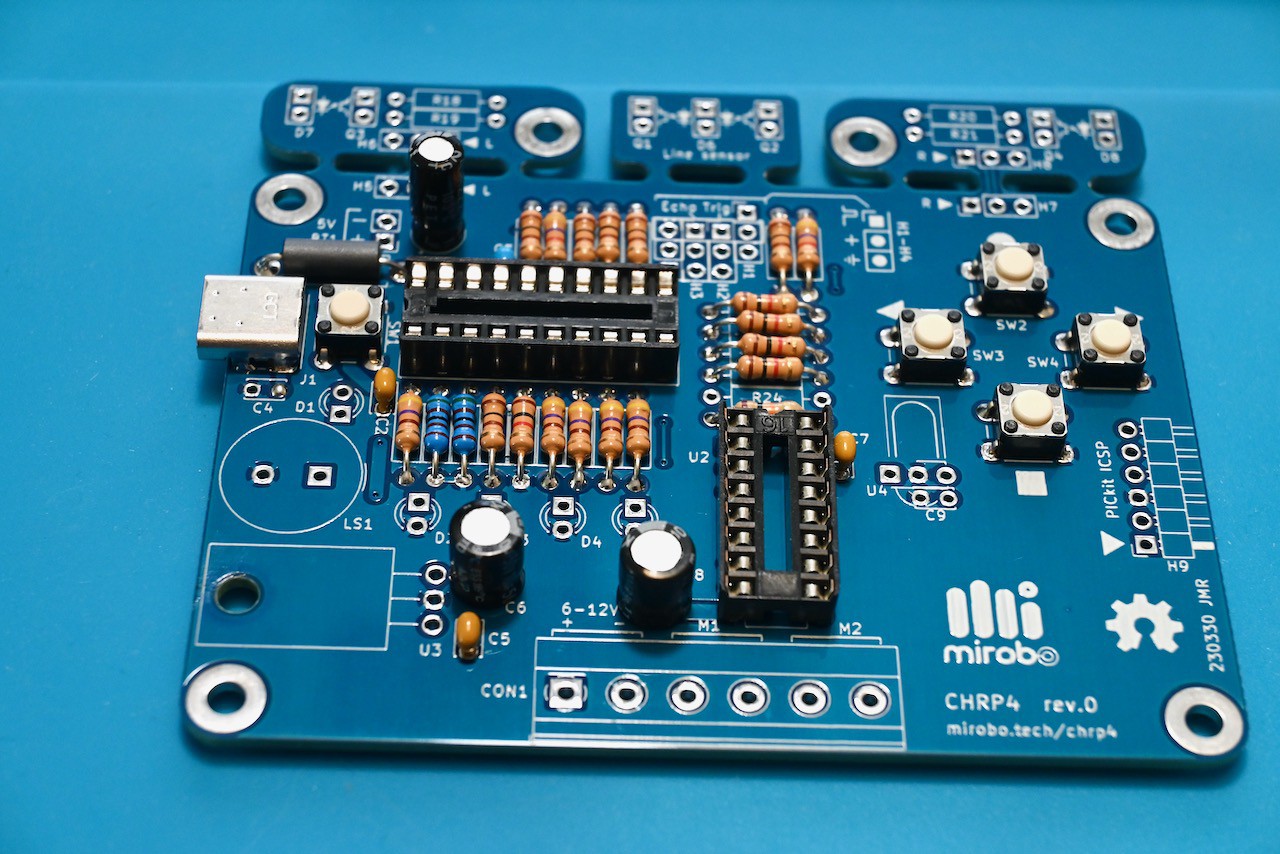
5Install the electrolytic capacitors
The electrolytic capacitors are polarized and must be installed the proper way. Each capacitor has a long lead and a short lead, and a white stripe marked with minus '-' signs on its body.
The long lead corresponds to the positive side, and goes into the square pad on the CHRP4 circuit board, which is also marked with a tiny plus '+' sign on the PCB silkscreen. The white stripe on the capacitor body matches the white-painted part of the capacitor symbol on the PCB, and is on the side closest to the capacitor's short lead, which goes into the round pad on the circuit board.
![]()
-
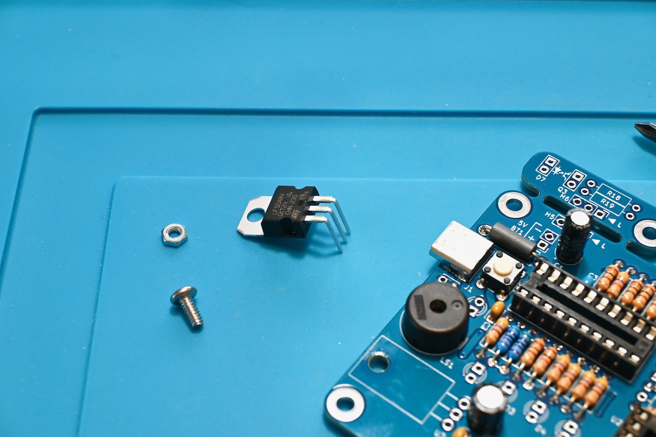
6Install the piezo beeper and voltage regulator
The piezo beeper is non-polarized, and can be installed either way in the spot marked LS1 on the PCB.
Align the LF50ABV voltage regulator over its location on the PCB and bend its pins down 90° using pliers before installing it into the board. It must be mounted onto the board to help dissipate heat while the CHRP4 is in operation.
![]()
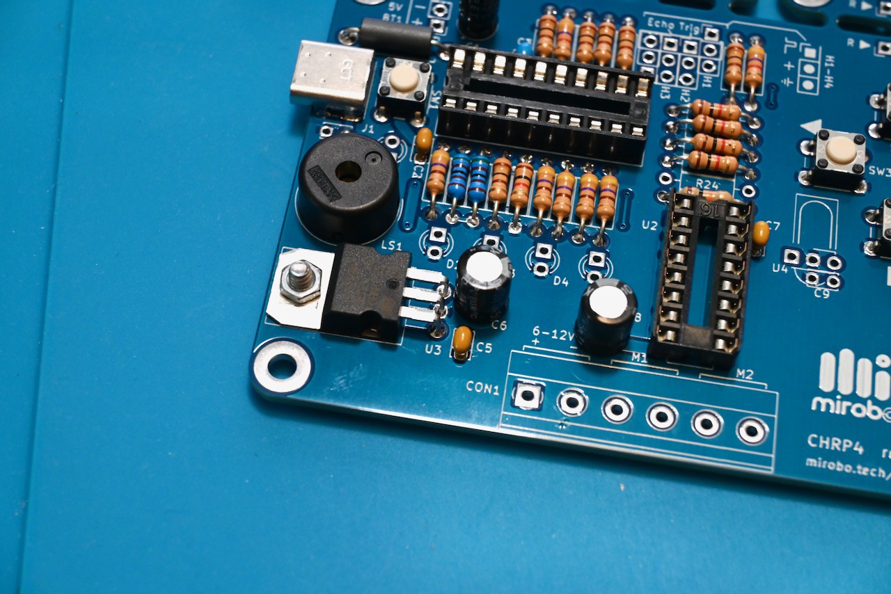
Insert a #4-40 screw from the bottom of the circuit board, through the metal regulator tab on the top, and fasten the regulator into place with a #4-40 nut. Installing it this way ensures the screw won't interfere when mounting the circuit board onto your robot platform. Solder all of the regulator pins.
![]()
-
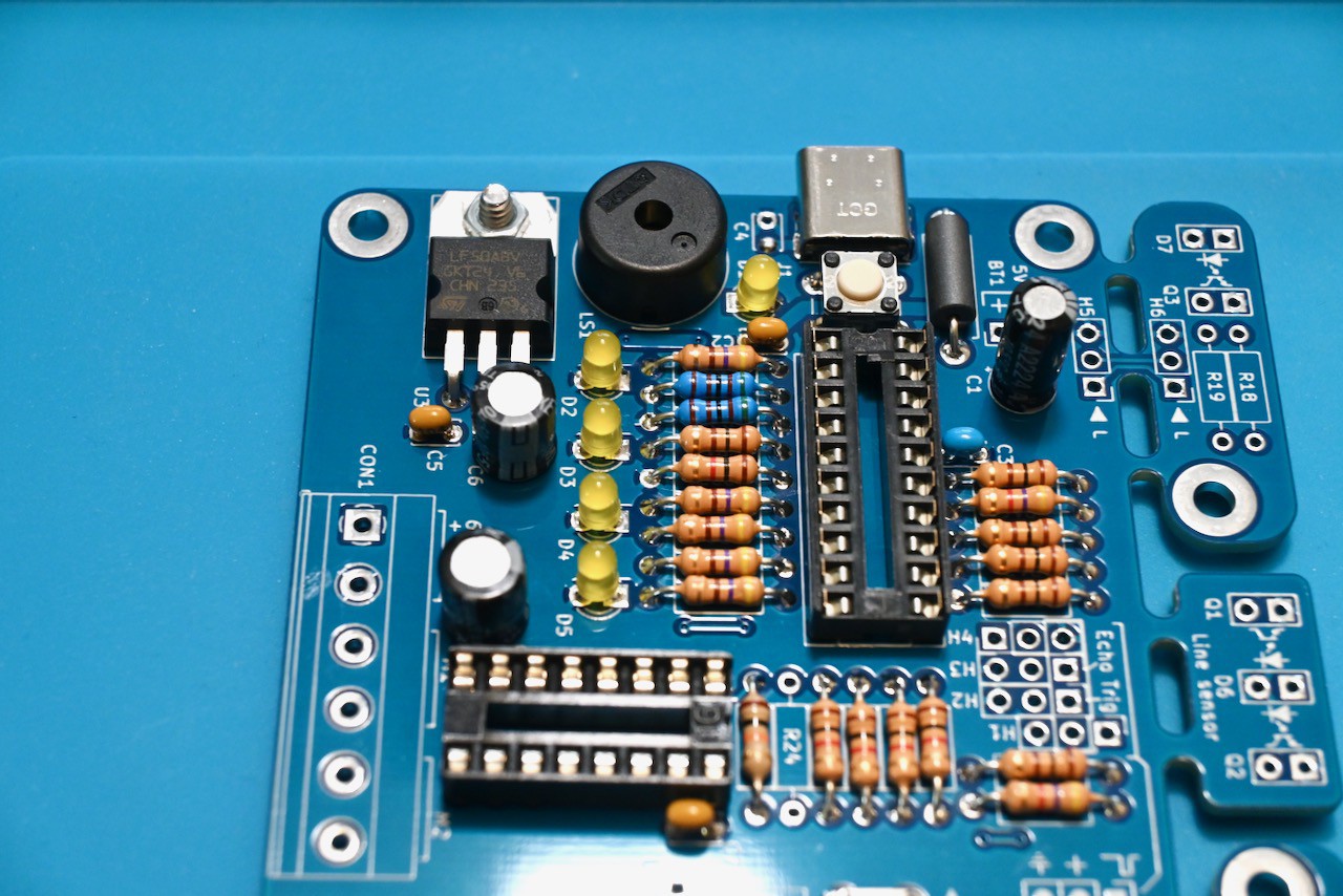
7Install the LEDs
The LEDs are polarized and must be installed in the proper orientation. As with the electrolytic capacitors, each LED has a long lead and a short lead, and the LED PCB locations feature a square pad and a round pad.
The long lead of each LED goes into the square pad, and the short lead goes into the round pad. (Note that this is an important difference from many other PCB designs and is done for consistency with the polarize capacitors, and to minimize confusion in this beginner project!)
![]()
Pro tip: an easy way to align all of the LEDs is to solder just one lead of each LED into the board first, then check and straighten each LED before soldering its second lead.
-
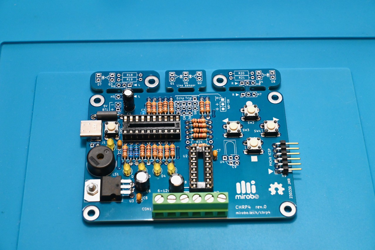
8Install the optional screw terminal strip and ICSP programming header
The screw terminal strip makes it easy and convenient to connect and disconnect CHRP4 from its motors and robot platform, but does increase the cost of the build and is not necessary for beginner learners to start using their CHRP4 to work through the introductory programming activities.
Install the screw terminal strip now if you know that your CHRP4 will be built into a robot. This way you won't have to clean the solder flux from the board again when you install it later. To save costs, the screw terminal can be omitted entirely by soldering the battery pack and motor wires directly to the CHRP4 PCB when installing it in a robot, later.
The ICSP (In-Circuit Serial Programming) header is used to pre-program the USB µC bootloader into the on-board PIC16F1459 microcontroller, or to program the microcontoller directly from MPLAB X if the bootloader is not used. An instructor may choose to pre-program all of the microcontrollers for a class so that the ICSP header can be omitted from each individual student build.
![]()
The completed line-following CHRP4 build with the optional screw terminal strip and ICSP programming header installed.
-
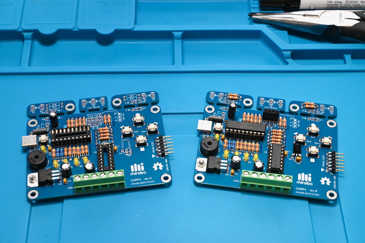
9Optional advanced robot build
The advanced robot configuration adds resistors to the break-away floor sensor modules, a 4-pin header socket for integrating an ultrasonic distance sensor module, and an optional IR demodulator. This photo compares the just built line-following configuration (left) to a fully built advanced robot configuration (right).
![]()
Note that in both configurations none of the floor sensing components have been added to the PCB. The floor sensors work best when the IR LED and phototransistors are installed at the proper height above the floor. Complete the assembly of your robot platform before completing the installation of the floor sensor components.
The line sensor module is designed to work only while it remains attached to the CHRP4 main board. If the line sensing components D6, Q1, and Q2 are installed and the robot is going to be upgraded to an advanced configuration using the dual floor sensors, the line sensor module has to be broken off to disconnect its circuits from the dual floor sensor circuits (it can remain attached if no parts are installed on it).
The dual floor sensor modules work while attached to the main CHRP4 board and can optionally be broken away and re-connected to the main CHRP4 by wires (3-wire servo extensions work well). This enables them to be mounted in the best physical location to sense the floor for your particular robot platform.
-
10Clean and test the CHRP4 board
Use the flux remover recommended for your solder to clean the board (unless you used a no-clean flux). Then, carefully straighten the pins of the microcontroller and motor driver, align the notch on each IC with the notch on its socket, and push the ICs into place making sure each of their pins goes in between the dual leaf contacts of its socket.
The PIC16F1459 in the CHRP4 kit is pre-programmed with the USB µC bootloader making it easy for all user programming to be done through the USB-C port. Connect CHRP4 to your computer using the appropriate USB-C cable and press SW1 (closest to the USB-C port) to start the bootloader. CHRP4 will appear as an external storage drive on the computer.
Use MPLAB X or MPLAB Xpress to build the CHRP4.0-Intro-1-Input-Output GitHub project, and drag and drop the compiled code to the drive representing CHRP4. The program will begin to run right away (make sure the MPLAB project is compiled using the modified linker settings shown near the top of the source code) so you can quickly see the results of your code changes.
CHRP4 USB robotics development board
A simple, inexpensive development board for learning or teaching beginner microcontroller programming and robotics.
Discussions
Become a Hackaday.io Member
Create an account to leave a comment. Already have an account? Log In.