-
1Introduction and some important notes
I love the RC2014's modular form factor and the fact that it's an 8-bit computer built from new parts. However, my own nostalgia is for character graphics and bitmapped screens rather than terminals and serial i/o. For me, the addition of sound and video cards takes the RC2014 to another level.
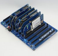
![RC2014 kits available from z80kits.com RC2014 kits available from z80kits.com]()
RC2014 kits available from z80kits.com The MSX1 standard specifies TMS99xxA video chip and AY sound chip. Modules already exist for the RC2014 that use these chips.
I should be totally upfront about the fact that my own goalposts have moved a bit. I began my Hackaday project with the statement: "I attempt to make an MSX1 compatible computer using RC2014, keeping to standard RC2014 backplane and modules as far as possible". Although my attempts at hacking standard modules such as RAM and ROM were successful, I've gone on to design custom boards (for reasons that I'll discuss when I come to those parts in the instructions). The only original RC2014 part left in my own MSX build is the backplane, since I have designed a combined CPU/clock/reset module.
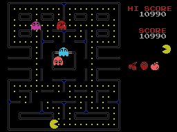
![MSX pacman MSX pacman]()
MSX pacman Having said that, this instructable takes a staged approach, starting with a working RC2014 (classic 32k, Pro or Zed) and transitioning to an MSX1-compatible computer, switchable back to RC2014 by swopping out modules for the original ones.
Some reasons why this may be for you
- The modular nature of the RC2014 makes this highly customisable and upgradable. It means that you can build the computer in stages, which is the way I've written the instructable.
- It also means that you can easily plug in regular RC2014 modules (for example, digital i/o ) and use those via MSX basic or machine code.
- If you're already invested in the RC2014 world, you'll already have a backplane and some modules such as clock and CPU. You may already have the TMS video card or the AY sound card. You could modify other existing modules such as ram and rom.
Some reasons why this may not be for you
- If you're not already invested in the RC2014 world, this is not be the most economical or compatible way to build an MSX computer.
- Please also note that this project aims to build an MSX1 computer. Some of the more impressive software, demos and games out there may be MSX2 or MSX2+ which have better video and sound chips.
- Dino's yellow board MSX and the Omega project are both MSX2+ computers that may suit you better. (Omega is open-source, the yellow-board project has schematics.)
- If you've started to build the yellow boards, no, my modules don't attempt to be compatible and mixing the two projects isn't supported.
- This project won't be open-source. I will be supplying everything you need and I prefer to sell assembled and tested modules rather than kits. I am also supplying a set of PCBs if that's your bag.
Overview of the staged approach
If you're still with me, this instructable takes a staged approach, outlined below.
First stage: RC2014 + video & sound (aka RC2014 + TMS + AY)
There is a small library of software and example code for RC2014+TMS video card (and in some cases +AY card). I am actively adding to it and J B Langston's library is excellent. Porting programs and games from other Z80 systems with similar screen resolutions is easy and I found porting 3D Monster Maze lots of fun.
Second stage - a working MSX1 with BASIC
The conversion to MSX1 by adding PPI, keyboard and BIOS/BASIC ROM gives you an advanced version of BASIC which includes commands for the screen modes, graphics functions like circle and line and the Music Macro Language (MML) for writing music . You could even give this BASIC a boost by using the RC2014 7Mhz clock.
Third stage - cartridge games / software
Adds a cartridge module which allows you to burn and run MSX1 16k and 32k rom images, including your own software if you write Z80 assembly. This opens up much of the huge library of software and games for MSX1, some of which look and sound fantastic and are very playable.
Fourth stage: tape saving and loading, joystick
More optional modules.
What you'll need
If you don't already have an RC2014 then buying an RC2014 kit and then the parts for this project will not be a cheap way to build an MSX, as I've already said.
Any of the 'backplane' RC2014s will be fine - classic 32k, CPM or Zed Pro. I have tended to work on a backplane-8 (with standard bus slots) and the smaller classic modules when building mine, but it does quickly become a squeeze when we start to add MSX ROMs / RAM / PPI and you will probably need to consider extending your backplane 8 (by connecting a 5 or another 8 ) or upgrading to a backplane 12 at that point.
You may already have an RC2014 TMS video module and RC2014 AY sound module but if not, you will need those. (Note that there is a complication with the sound card - the R5 AY card uses ports considered traditional for RC2014 but can't be jumpered for MSX ports. The newer R6 AY board can use MSX ports but not the traditional RC2014 ports.)
To go beyond RC2014+TMS video card, you will need to be able to burn a ROM image to an EPROM. (the MSX1 BIOS and BASIC as well as any cartridge ROMs or your own software that you want to run) The ROM images can be found online but I don't have the rights to distribute them.
There are other core modules which are definitely required, such as the PPI and some kind of keyboard solution. There are some optional modules such as the dual-joystick and tape interfaces.
-
2Adding video and sound cards to RC2014 aka RC2014+TMS+AY
In this step we will add the video module and optionally the sound module at that point you'll be able to run demos and games written specifically for this setup. Unless you want to run MSX BASIC or MSX games then you may want to stop there.
RC2014 + TMS
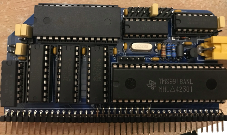
The TMS9918A is a very capable chip (as used in many '80s computers including TI-99, Colecovision, Memotech MTX and MSX). It has a text mode, tile mode, multicolour bitmap mode and 32 16x16 sprites. Video RAM is 16k of dedicated RAM which is in addition to your machine's regular RAM and communication with the video ram is very fast.
Be aware that the chip is no longer made. I have found that it's easy and cheap to get hold of and the ones I've bought do appear to be genuine.
The module I recommend is by J B Langston and is open-source. He recommends and approves the kit from Michael Kamprath and I also have permission to sell assembled modules, which are complete with TMS chip and thoroughly tested.
Port settings
There are several configurations available which are more thoroughly detailed on Mr Langston's Github page. Here is a simplified guide with the relevant ones for this project.
For 'classic' 32k RC2014 (specifically with ACIA/68B50 serial) I recommend Tatung Einstein ports, 08/09:
![]()
For CPM RC2014, I recommend the MSX ports 0x98/0x99:
![]()
(Note that the Github page for this module says for J4, MSX "3rd from right" but the setting is as above which I feel is best described as 'fourth from right').
Mr Langston's repository has software examples, his library is brilliant. If you want to write your own Z80 or C code targeting this video chip then I highly recommend using that.
Depending on your configuration, you may have trouble building and running those, so for convenience I have provided pre-built examples for 32k RC2014 and cpm. (For ROMWBW, you will have less trouble with J B Langston's examples). My examples also include my port of 3D Monster Maze and my own game. I'm working on Mazogs and there may be others.
If you want to use the library to write your own code, one important note is that in tms.asm, TmsProbe: will check a list of ports to detect your card. One of the ports on the TmsPorts: list is 0xBx and if you're using CP/M then this conflicts with the ROM/RAM paging and unfortunately the code probes this port first. You will need to take that port out of the list and make TmsNumPorts equal the number that you want to leave in. Or just put your port number in TmsPort: and leave out the call to TmsProbe:
At this point you'll still be using the terminal as before when the computer starts up and loading the programs in the way that you usually do (I'm providing IHX files for the 32k machine and .coms for the cpm). The composite out should give a valid but black signal, 60Hz if you're using TMS9918A. When your program runs, it'll use the TMS display.
Try a simple demo like "ascii" first to make sure that your card is working. Other demos will demonstrate other aspects of the chip such as bitmap mode and sprites.
Adding AY
I recommend the YM/AY module by Ed Brindley, which is also open-source.
This card has been around for a long time and is popular in the RC2014 community.
But please note that revision 5 and earlier can be jumpered to ports 0xD0 and 0xD8, which I consider 'standard RC2014 settings', and most of the RC2014 software will expect to use those ports.
MSX uses ports 0xA0 and 0xA1. Unfortunately, there is a complication here. The older AY boards can't be set to these ports. Ed has revised his design and the R6 board can use MSX or Spectrum ports, but not the established RC2014 ports.
What this means is that
- If you have an AY card already, R5 or earlier, then you'll be able to use it with the RC2014 setup but it won't work with MSX software.
- If you're writing and building your own software and sticking with the RC2014+TMS+AY setup, then this isn't an issue because you can configure your software to use the ports that you have.
- If you want to go forward with the MSX build then you'll need an R6 AY sound card.
The only demo that I have (so far) for RC2014 that uses both AY sound and TMS video is the Nyan Cat demo, which is well worth running. The builds in my own collection currently use RC2014 ports, though I will be adding built examples that are configured to use the R6 AY sound card on MSX ports.
(interesting note: The Nyan demo makes use of the little-used 'multicolour hires mode' which can set any 'pixel' to any of the 16 colours, but those pixels are huge - 4x4 - see below.)
-
3A working MSX1 with BASIC
![]()
The conversion to MSX1 by adding PPI, keyboard and BIOS/BASIC ROM gives you an advanced version of BASIC which includes commands for the screen modes, graphics functions like circle and line and the Music Macro Language (MML) for writing music. You could even give this BASIC a boost by using the RC2014 7Mhz clock.
Clock options
If you have an RC2014 dual clock, this is ideal. You can jumper it to a near-MSX-speed of 3.68Mhz (MSX spec says 3.58). You also have the option of giving your MSX BASIC programs a boost by running the computer at full RC2014 speed 7.3Mhz, which appears to work fine.
I have built myself an MSX clock module using a spare RC2014 clock pcb fitted with a 3.58 crystal, actually 3.579 which was the closest I could get (in my case the small 'ext clock' pcb which isn't available any more but any of the RC2014 clock module PCBs will be fine) .
Spencer has no plans to design an official RC2014 combined clock/CPU module so I've recently designed myself a 'spacesaver' CPU+clock+reset circuit. This saves a slot, and if you're using a clock without a reset circuit then that's a nice-to-have. I'm currently supplying this board as part of the set of 9 MSX2014 boards.
CPU options
Any RC2014 Z80 module should be fine. I've run this project using a classic CPU module as well as the standard CPU module from my Pro. These do little more than connect your Z80 to the bus.
See the above comments about my spacesaver CPU+clock+reset.
PPI module
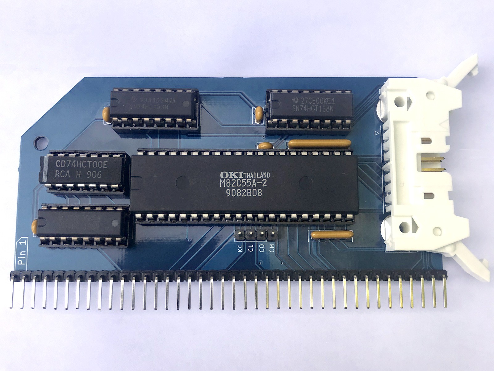
You will need a PPI (programmable peripheral interface) which is the i/o logic. It's based on the 82C55 chip which is now out of production but hasn't been out of production long and so there's plenty of new stock about. This provides three programmable ports which the MSX uses for keyboard scanning, memory slot selection and provides some other lines such as cassette output and key click.
This project uses 4 spare backplane lines to carry the decoded active-low slot selection lines, which makes it very easy and neat to have a RAM or ROM module be selected according to the appropriate backplane bus line.
I am supplying this module built and tested. Optionally with the ROM/RAM and cartridge modules as discussed below.
![]()
It connects to the keyboard using a ribbon cable with IDC 8x2 connectors. That latching connector is important because it helps with extracting the plug which can be tight.
Keyboard options
The system scans a matrix of up to 11 rows and 8 columns (it contains various control and modifier keys and can contain a numpad if you want). As usual with the MSX, you can't just hook up switches, there's a certain amount of multiplexing involved. The PPI provides the bi-directional ports and the keyboard itself needs to do some decoding (rowA-D into row 0-11).
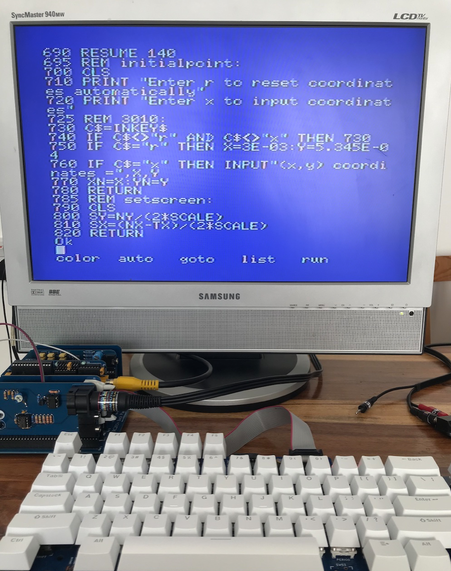
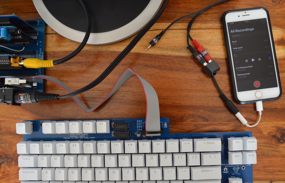
The Omega project has a separate keyboard which is entirely compatible with this project and I found it surprisingly cheap to build. I found a set of Gateron switches on eBay for £20 and bought some very cheap keycaps for £6 which almost entirely have the correct symbols (eg @ sign on the 2 key). I love using this keyboard (see picture above). It has a modern layout and has the important keys for using MSX BASIC and some games (eg 'select' and 'stop'). In order to make mine I obviously ended up with some spares, speak to me if you're interested in one of those.
I've also designed a USB keyboard adaptor which works surprisingly well. The circuit is solid, it just needs some wrinkles ironing out in the firmware. One downside of this solution is that it uses a microcontroller, something I'm not particularly keen on in retro computing. Some upsides are that it's a cheaper solution than building a mech keyboard and that it also has a serial port so that you can paste basic programs via a terminal. If you're interested in one of these, please speak to me.
BIOS/BASIC ROM and RAM
You will need one ROM containing the MSX1 BIOS which is 16k starting at location zero, and the MSX BASIC which is another 16k starting at $4000. You can obtain this as a single 32k image online, contact me if you're unable to find it.
[EDIT]
These instructions originally said that it was necessary to use modified or custom ROM and RAM boards, because the slot selection lines are essential. However, I've since had an 'MSX2014' working with standard unmodified RC2014 ROM and RAM modules. See the project log here. It's far from ideal. BASIC works, tape loading may work, some cartridge roms may work, but it won't be as good as using RAM/ROM modules with slot selection. You may like to try that though as an intermediate step.
[/EDIT]
My boards are designed to take the 27C512 EEPROMs, which are 64k and you can program over and over. These are not in production but not too difficult to find. And the 62256 RAM which is in production and easy to obtain.
You will also need 32 or 64k of RAM (if 32k, it must start at $8000). 32k is fine, some games may use 64, but it's not common or easy to use the extra 32k because that involves using the BIOS routines to do the switching. I may eventually extend my RAM/ROM module to have the full 64k.
It's important to know that the MSX is designed to have 4 'slots' for RAM and ROM which can each potentially be 64k. This isn't simply 'mapped', but 'sideways' - you can potentially have 4 x 64k, selected as needed. You'll see from the information above that even with a simple system there can easily be some overlap. The PPI and the slot selection lines are required to manage all of this.
I began this project by bodging existing RC2014 ROM and RAM modules as this fitted with my original goal of using as many standard RC2014 parts as possible and I did plan to give full instructions for doing this. There are many reasons why this is very difficult and it makes much more sense to drop in specially-designed modules:
- The bodged modules look very untidy
- Spencer does not supply kits or pcbs for the core modules like ram and rom
- The MSX ram/rom modules are simpler than the RC2014 - less logic needed
- The modifications are reversible but not easily. Much easier to have a set of MSX RAM/ROM modules and a set of RC2014 modules
- There are many versions of the RC2014 modules with different layouts and that's not counting third party modules. Telling you which points to connect and which pins to fold out is impossible without identifying your particular module and studying its schematic.
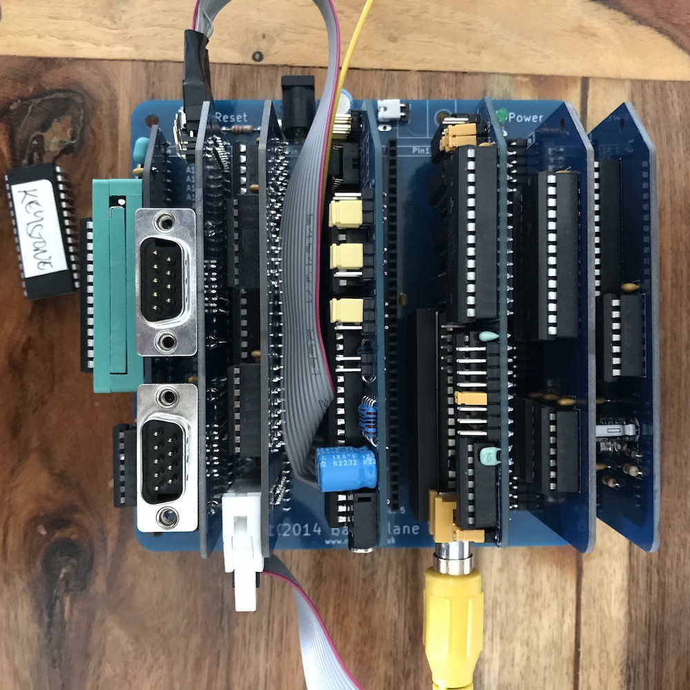
Instead I propose including the pcbs for my own MSX2014 RAM/ROM and cartridge modules with my PPI module. These consist of one standard-sized module which holds the BIOS/BASIC ROM and 32k RAM, and one 'cartridge ROM' which has a ZIF socket for game ROMs. (dealt with in the next step).
![]()
If you do wish to go ahead with modifying your own ROM / RAM modules then here is an outline of the information you need:
- My PPI module uses the spare 4 bus lines (pins 37-40 bus) as 'active-low' slot selection lines.
- Bus pin 37 is designated 'SLOTSEL0' and should select your BIOS ROM, which contains the MSX BIOS/BASIC at $0000 to $7FFF. When high, should leave that ROM disabled
- Bus pin 40 is designated 'SLOTSEL3' and should select your RAM. This can be 32k in the upper 32k, or 64k in the full address space. When high, should leave the RAM disabled.
- Bus pins 38 and 39 are designated SLOTSEL1 and 2. Your cartridge rom should be selected when one of these lines is low. 16k and 32k cartridge ROMs usually start at $4000 although I don't think this is a firm rule. The easiest way to achieve this is to connect or jumper your 64k ROM so that it starts at $0000 and burn the chip so that the data starts at the right place (usually $4000)
- Always use a spare logic gate on the existing rom or ram module to include the appropriate SLOTSEL line in the chip's chip or output enable.
The 'cartridge ROM' module
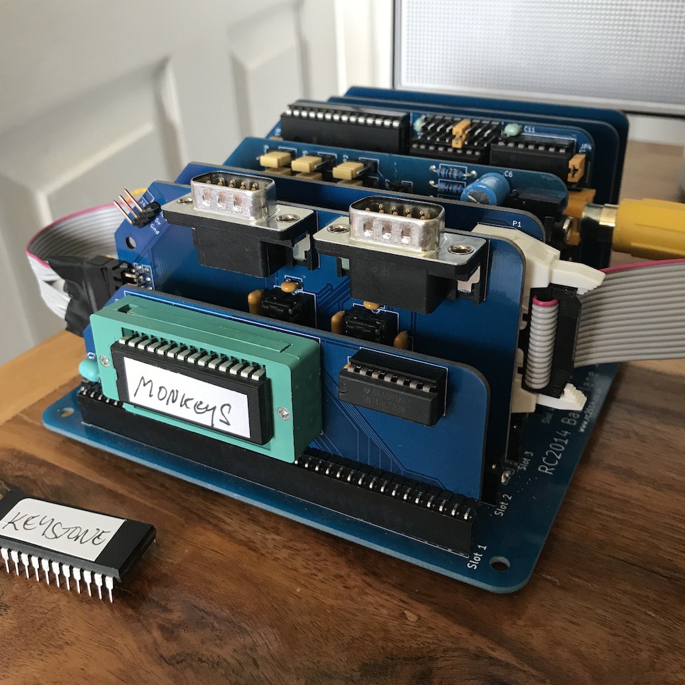
This module is designed to take a ZIF socket and this is recommended as it allows you to swop ROM chips easily and without stressing the legs. It may take a little trial and error to get a game running.
It's designed to take a 27C512 (64 kilobytes) and it's highly recommended that you use an electrically erasable (eeprom) chip for convenience.
Most cartridge rom files are designed to start at $4000. This can be determined by looking at the first few bytes of the .rom file.
![]()
In this example, the first couple of bytes are the ascii codes for "AB" which indicates a cartridge file. The next two bytes in reverse order are the start address of the program. In this case $4018 which is in the middle of the second row, after the name 'PACMAN'. So we can tell that this rom (like most) is designed to appear in memory at $4000.
The 'cartridge ROM module' will make your rom chip appear starting at address 0000. You might expect it to contain the logic to make your rom (burned with data starting at 0000) appear at $4000. The reasons for the simpler choice is that it would cause problems with 32k roms, and that it offers the flexibility to put your data where it's needed (roms don't necessarily always start at $4000).
This means that you'll probably need to pad your rom file after determining that it should appear at 4000, before burning it to a chip.
-
4Tape saving / loading
If you spend any time typing in your own basic programs, then you'll want a way to save and load.
(incidentally I like writing Z80 assembly and have found that flashing to a rewriteable W27C512 is a great way to run my own programs. See my project logs for more about this).
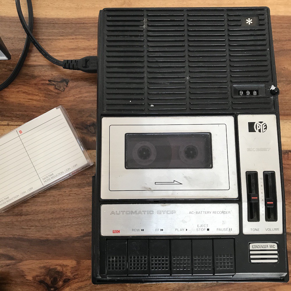
The method that many of us grew up with was saving and loading to tape. If you have a real tape player with 3.5" mono in and out aka 'ear' and 'mic' sockets and a spare cassette tape then it's fun to relive those experiences.
![]()
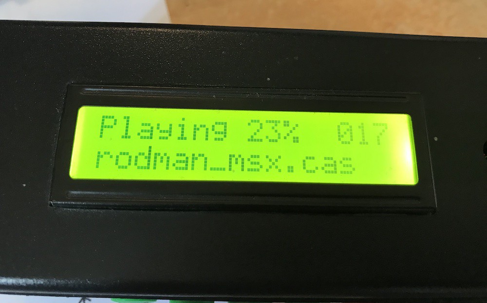
A device like a casduino / maxduino may make this more reliable.
![]()
For this reason I designed my tape module. It has the MSX-compatible 8-pin DIN as well as the sinclair-style ear and mic jack sockets.
Important note: Some other computers; BBC, Electron, Oric used an 8-pin DIN but the connections are not the same as MSX. For a computer that set out to set standards, I find this a little ironic. It's a great idea to use the DIN socket with an MSX cassette lead, as this breaks out the 'rem' connection. If your cassette player (or casduino) has this feature then it helps by starting and stopping your cassette as required.
Retro Computer Shack makes some great leads and he does make an MSX tape lead.
Find your favourite MSX documentation for more details about the syntax (mine is Spectravideo and MSX Complete User Guide by electricadventures.net) but CSAVE"myprogram" CLOAD"" will get you started.
Real cassette
Note that more modern cassette players may have a stereo jack. Therefore the signal will be divided into L and R. If you plug a mono jack into that socket (or plug a stereo lead into the mic/ear socket) then at best you'll get half the signal and lose volume, which is important here. Make sure your player has a mono out, or convert the stereo out to mono.
I've had to play with the resistor values on my board. In particular R11. My BOM gives details, but I found that for a self-saved program on a real tape, omitting this resistor completely gave me the best results.
As with real tapes back in the day, experiment to find the volume level that works best. I found that the component values for the output signal mattered little as the tape players I have seem to do their own input level control.
CASDUINO / MAXDUINO
I haven't been successful with this method, but I believe it should work. My own 'duino was a txzduino, which doesn't play .cas files. But it can be upgraded to maxduino software (which combines casduino and txzduino) which I have done. It does play MSX .cas files and the level seems fine but I think it's the wrong baud rate. Maxduino software does have a menu where you can change this but my buttons don't operate the menus properly and I haven't been able to change it. By default, MSX uses 1200 baud but this can be changed from BASIC to 2400 (see your favourite MSX BASIC reference.)
Phone or computer
I've had great success using my iPhone (and computer, but that it's quite as convenient). You can use the memo app to record and play back yoru own programs, trim any silence from the start and end, name them and scroll through to find the recording you want.
For games in .cas format, you will need to convert these to .wav (or find the .wav file if someone has already done it). I use mcp to do that conversion, it works beautifully. I drop the .wav onto my phone, find it in my Files app and press play.
Interfacing is not so easy. I can't comment on Android phones but my iPhone has a single lightning port. For headphones I use a lightning -> 3.5mm jack adaptor (you'll already own one of these if you have an iPhone and like wired earbuds / phones). The socket is a 4-pole socket (trrs) which has mic, L, R and gnd. I've made my own lead to break the 4-pole socket into 2x mono jack sockets and from there I use either the Sinclair-style dual mono lead, or the MSX DIN -> 3 jack lead. It's a little clunky but it works beautifully.
![]()
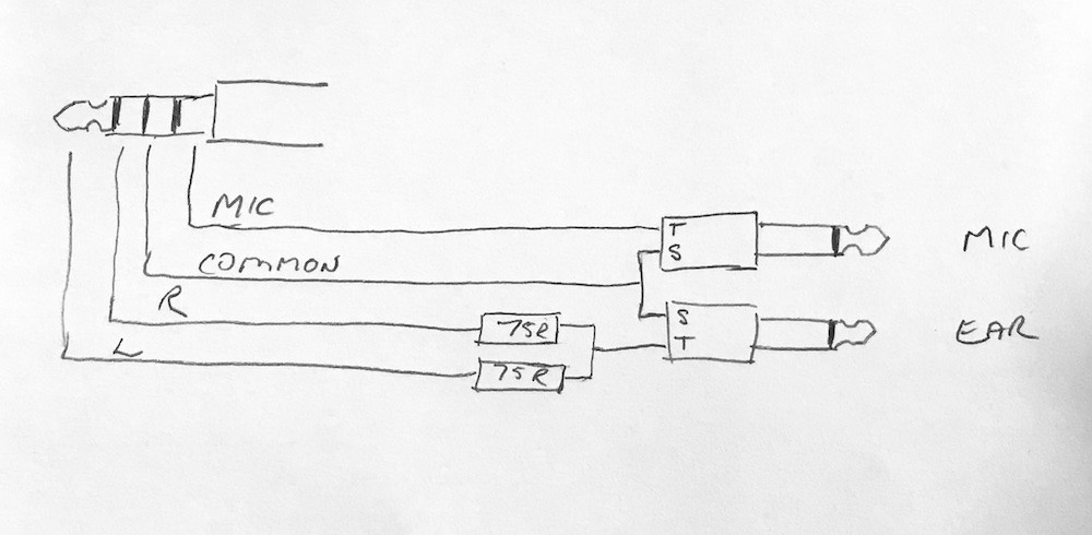
Here's my circuit for breaking the 4-pole to the 2x mono. The important thing here is that (as with stereo out from a modern cassette player) L and R contain half-strength signals and it's important to combine them for a good volume. I don't think it's advisable to just wire them together and so my lead contains a simple 2-resistor mixer. Lowering the value of these resistors reduces the level that the phone's volume needs to be. I've gone as low as I dare with the resistors (2x 75 ohm) and that allows me to use the iPhone at 5 clicks below full volume.
![]()
(This diagram confusingly shows mono jack *plugs* wheras my own lead has sockets to take the plugs of the DIN lead).
PCB connections
There are a couple of connections that unfortunately aren't carried by the backplane and will need to be made to other modules with jumper leads.
For saving, the signal is marked CO on the PPI module, and will need to be connected to CO on the cassette module. Optionally you can connect CM on PPI and cassette module for the 'rem' functionality.
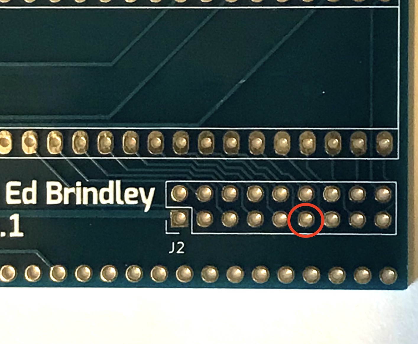
For loading, the IOA7 is marked on the cassette module and needs to be connected to IOA7 on the sound module, Marked below:
![]()
Note that if you're using the joystick module, and have 16 or 18 of those connections joined to the joystick module by ribbon cable (see the 'Joystick' step) then IOA7 is handily passed through to a clearly-marked pin on the angled corner of the joystick module.
-
5Joystick module
This is a very simple module, it contains the two joystick ports and some logic.
![]()
It depends on the sound module for the i/o. As per the earlier instruction step, the *R6* of Ed's sound module is required because earlier revisions can't be jumpered to MSX ports.
The joystick module requires wired connections to the sound module which unfortunately aren't carried by the backplane.
![]()
The sound module has 2 rows of 9 pads and the joystick module has a matching footprint.
Ideally, a ribbon with 2x9 female plugs (0.1" / 2.54mm pitch) would be ideal but this is an odd number. A 2x8 IDC will do - if the joystick module is plugged into the backplane. then it'll get its 5v and gnd from the bus and you don't need pins 1 and 2. (pin 1 is the square pin, pin 2 is )
In order not to use an extra slot on my backplane, you'll notice in the picture above I've wired the ribbon directly into the sound module, with a female 2x9 on the end that plugs into right-angled headers on the joystick module. Just be careful with the orientation (pin 1 is the square pin on both boards, and pins 1 and 2 are the ones you don't necessarily need).
If you do make all 18 connections, then the joystick module doesn't need to be plugged into the backplane which may save you a slot.
MSX on RC2014
in which I attempt to make an MSX1 compatible computer using RC2014, keeping to standard RC2014 backplane and modules as far as possible.


Discussions
Become a Hackaday.io Member
Create an account to leave a comment. Already have an account? Log In.