-
A tidier computer
07/23/2024 at 16:02 • 0 commentsTwo issues for me have been the composite video output of the real TMS chip, and the untidiness of having connections between modules, particularly between the sound and joystick.
I have been improving my own TMSEMU module so that it works in the MSX2014 but This new RC2014 module from Les Bird solves many of my issues.
![]()
I'm impressed with what he has packed onto this standard-sized module; video, sound and joystick ports.
The video is generated by an FPGA flashed with the F18A code. It's not a real TMS chip but I feel that's a worthwhile compromise in order to get a sharp picture with the convenience of HDMI.
The sound (and some i/o) is provided by a real AY chip. There's only room for pin headers and so these ribbon cables with the d-sub connectors are necessary.
![]()
The result is a much tidier computer with more free slots. I'm very happy with this.
-
Addendum - MSX BASIC working without modifying ROM and RAM modules
11/30/2023 at 14:08 • 0 commentsThis is merely a bit of a curiosity, I don't intend to explore this further now that I have a 'MSX2014' which works pretty well.
However, I did state in my earlier logs and instructions that it's necessary to add slot selection lines to ROM / RAM / Cartridge ROM modules. I wasn't able to get BASIC working at that point without doing that.
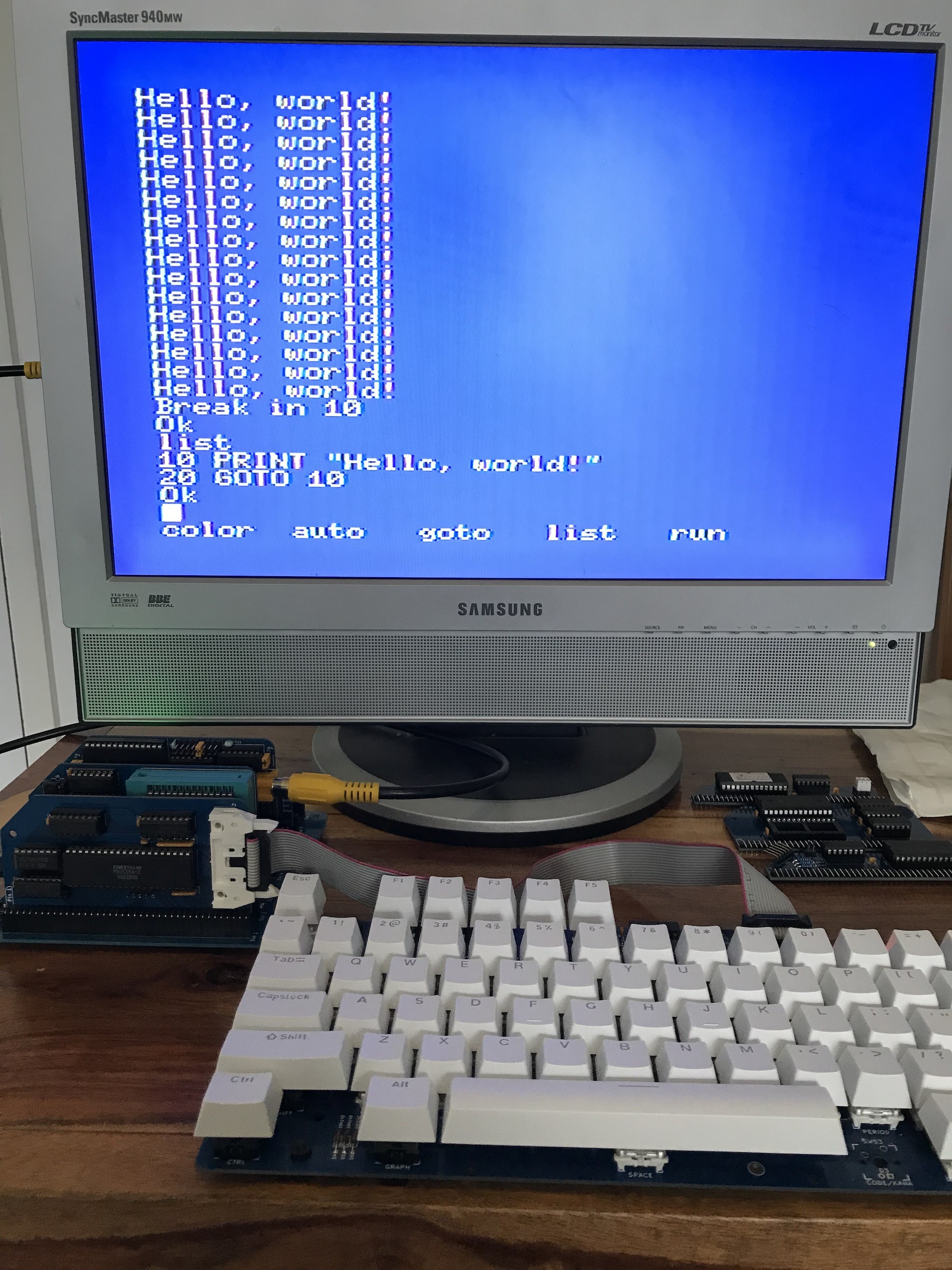
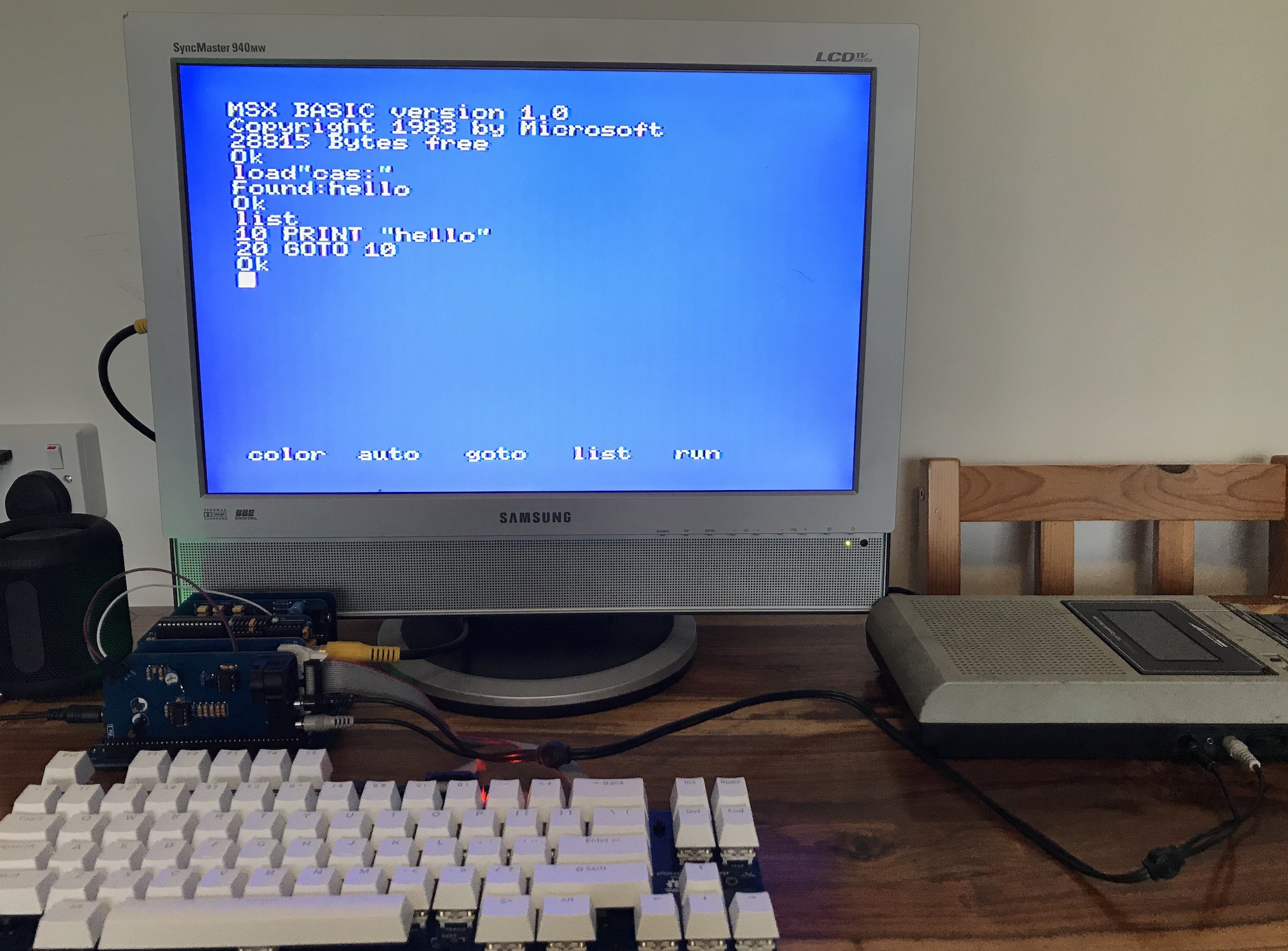
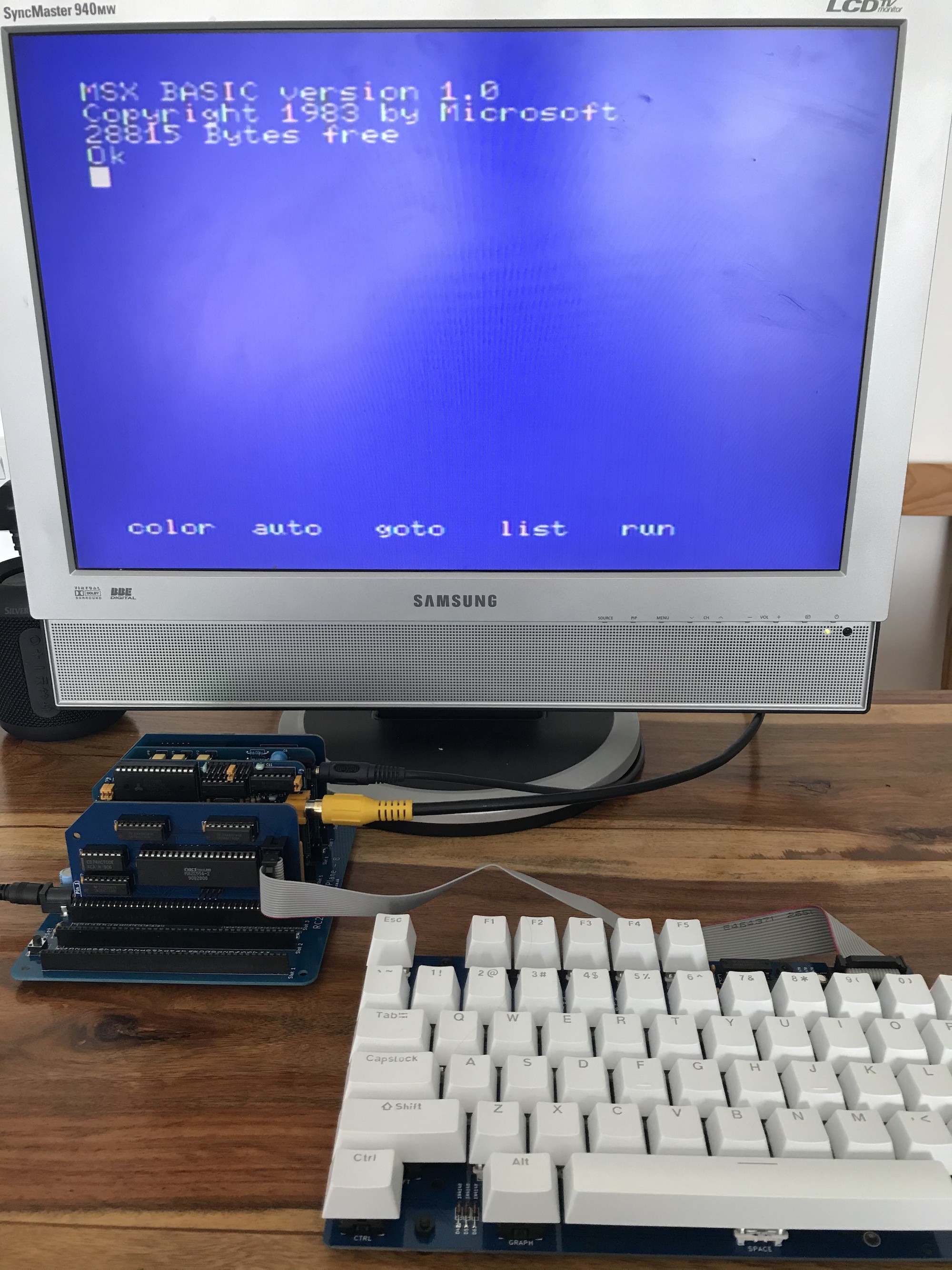
At that point though, I'd been trying to use c-bios, which I believe was never going to work with BASIC anyway. Out of curiosity, I took a standard RC2014, minus the serial i/o module and plus my MSX PPI module and lo and behold:
![]()
This is far from ideal, and I'm a little surprised that it's working at all, but it is working.
The first thing that the BIOS does is to switch in each slot in turn and see what RAM it can find (the longest contiguous amount of RAM that it can find, counting down from FFFF, is the slot that it will use for RAM. It also tests each slot to see whether a cartridge ROM is present. The slot selection won't work in this case and it'll see the ROM and RAM on every slot.)
But it does start, and BASIC appears to work well. This is working at the standard RC2014 clock speed of 7.3Mhz.
I assume that tape loading would work if I used my tape module (This would require a bigger backplane as the tape module depends on the AY sound module). Cartridge ROMs may work (again, haven't tried) if you make a rom with the BIOS in the first 16k and a 16k cartridge rom in the next 16k, and RAM in the top 32k.)
Note that I've had to use the bigger 64k ROM module, jumpered so that my ROM (BIOS and BASIC) is seen in the first 32k. It may be possible to bodge the smaller RC2014 Classic ROM module so that 32k of ROM is seen, but I haven't gone into how to do that.
-
Yet another joystick module and a milestsone reached
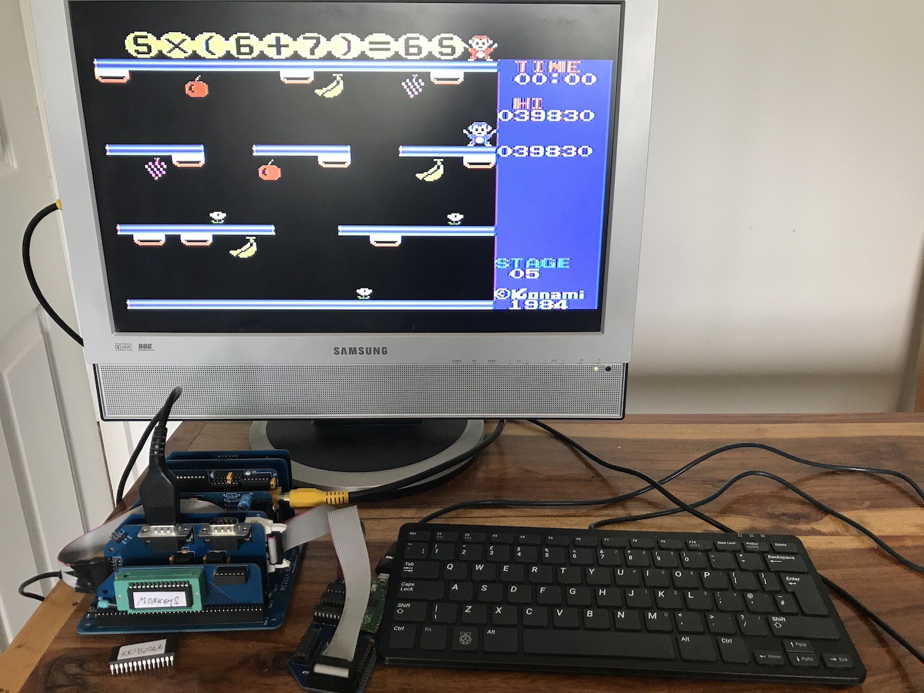
08/17/2023 at 13:31 • 0 commentsFinally... the third iteration of the joystick module works without bodge wires. I've been using it to work on my hi-score for Monkey Academy. Beat that!!
![]()
I've had no luck so far with the floppy drive module. I believe it should work but it hasn't yet. This isn't so important to me, just a nice-to-have if I can manage it.
I'm calling this a milestone rather than a completed project because I do have an (ambitious) idea that I'm going to run with. I won't reveal that just yet until I've made some progress.
Otherwise I'm just going to enjoy using my MSX2014 to do some fab things; use MSX basic, port some games to MSX cartridge, see which other RC2014 modules will work.
Now that I have some complete sets of good boards for this project (including Omega keyboard pcb, not in the picture above) I'm listing those on Tindie.
-
Joystick ports and other refinements
07/11/2023 at 15:04 • 0 commentsThis week I've received two new modules.
The first is something that I didn't really consider essential - especially after making such a nice mechanical keyboard. But I find that it makes games so much more fun (and I'm getting better scores!)
![]()
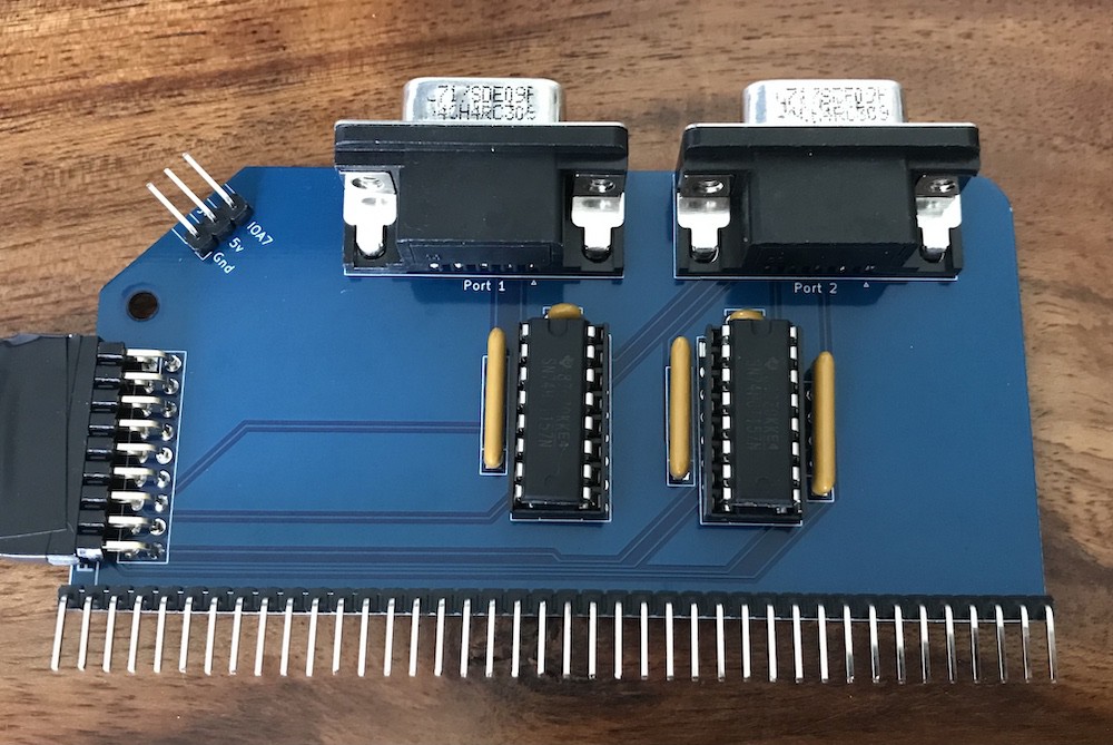
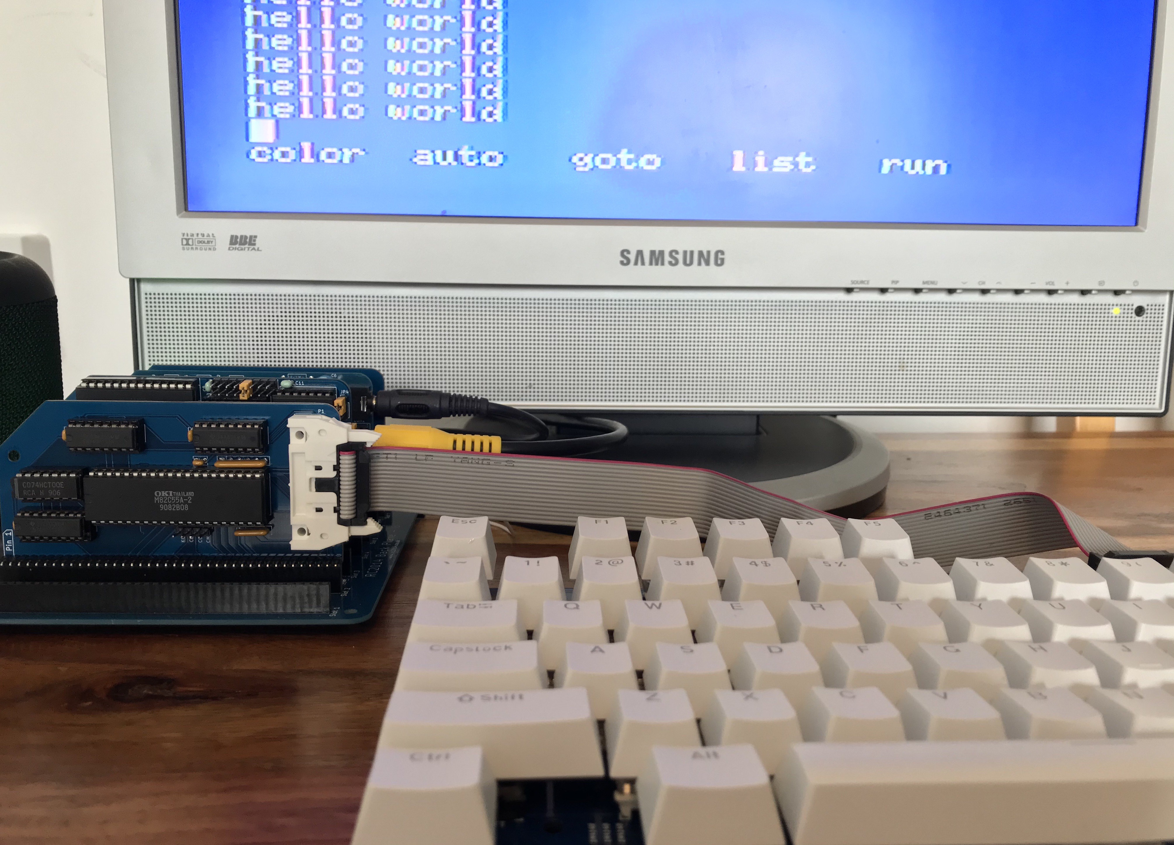
The MSX standard allows for two game / general purpose ports. Like everything MSX, it's nowhere near as simple as reading a hardware port. The ports are read via the sound chip (it has two configurable i/o ports of its own) with some multiplexing. Therefore this module needs connections to the YM/AY module. I've made a ribbon lead which doesn't look too shabby.
![]()
We already have a similar ribbon between PPI and the keyboard, so the new one between the game port module and AY doesn't look out of place.
I've been exploring more games and have found a port of the 'fictional' Spectrum game, Nohzdyve, which I absolutely love on the Speccy and this version is even better. It controls a little differently. Rather than simply moving left and right (and continuing to move after you've let go of the key), you still continue to drift left or right, but more slowly than when you actually move left or right. It's hard to explain and not something you immediately notice but makes it more fun to play. Like most of the games I've tried, it supports the joystick.
You can see from the picture above that I'm continuing to use a backplane 8. This is only possible with this new module:
![]()
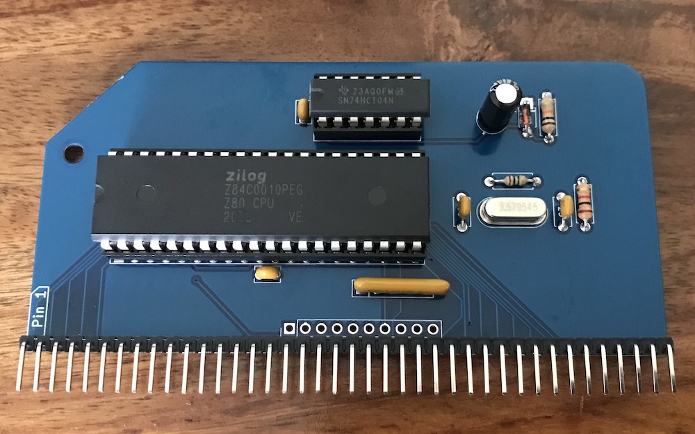
I'm calling this the 'spacesaver'. I respect Spencer's decision to keep the official RC2014 highly modular, but with this project I've found it a little frustrating that the CPU and clock should take two backplane slots. Here we have the Z80, a clock generator and a reset circuit on a single module. The 'enhanced bus' connections are there too if anyone wanted to use this with an enhanced-bus RC2014. I've fitted this with a 3.58Mhz crystal so that it's specific to the MSX2014 project. The reset circuit means that I no longer have to press the reset button when I power up.
![]()
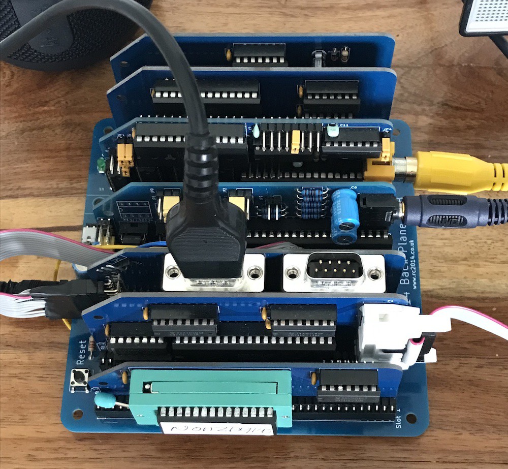
The whole thing looks very neat. You can see that I'm down to seven modules on a standard backplane 8 (I have a heatsink on my TMS video chip, unfortunately meaning that it hogs the slot in front of it). This works fine if I switch the cartridge ROM module with the tape module as needed (which are mutually-exclusive anyway).
This setup is working beautifully. Unfortunately I've got to order a new version of the joystick module pcb because I had to do some troubleshooting there and found a connection I missed - the version I'm using has a couple of bodge wires.
Apart from that - what next? I'm not quite sure. I have been tempted to use an enhanced-bus backplane and put those joystick and cassette signals on the enhanced bus. I'm still sleeping on that one. I'd also like to learn about floppy interfaces and possibly get MSXDOS running with a Gotek.
I guess I should get on with some of the software projects that I've started, which for me is the main point of building this computer. Here's some of the cool stuff that I've been messing around with. They include Conway's Life, using RC2014 modules with the MSX, type-ins from a book and from the web.
![]()
-
More programming / using RC2014 modules
07/05/2023 at 20:46 • 0 commentsOne big advantage of building this MSX computer using the RC2014 backplane is that you can use many of the RC2014 modules.
First I tried the 8x8 LED matrix. Using BASIC and 3.58Mhz it was a bit flickery, so it was necessary to switch to assembly. I then found my preferred way to work was assemble on my Mac and burn the program to a 'cartridge' ROM.
![]()
This made quite a neat development cycle. These little programs are nothing to shout about but they do demonstrate that these modules work well with this computer and that it's perfectly easy to write code to use them.
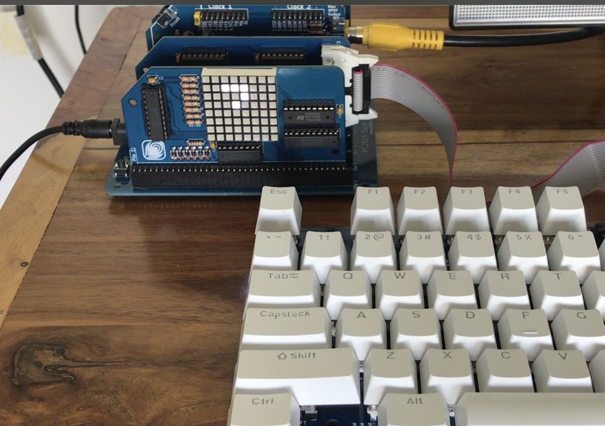
First I tried the Conway's Life that I'd already written for the 8x8 matrix on RC2014. I thought that this would be little more than a copy and paste into a cartridge template*. In the picture below and in the video I'm using the full RC2014 clock speed of 7Mhz for the best flicker-free display and the fastest regeneration cycle.
![]()
The biggest problem I had was due to me forgetting that any 'variables' declared within the ROM space would not work! They have to be replaced by a reference to a location in the RAM space.
I also had a few calls to the CPM Bios for things like keyboard input and screen output, but there are similar routines in the MSX BIOS.
The video below shows my Conway's Life for 8x8 matrix running. It wraps both vertically and horizontally, as you can see from the glider. Before that is an oscillator it came up with which has about 20 steps.
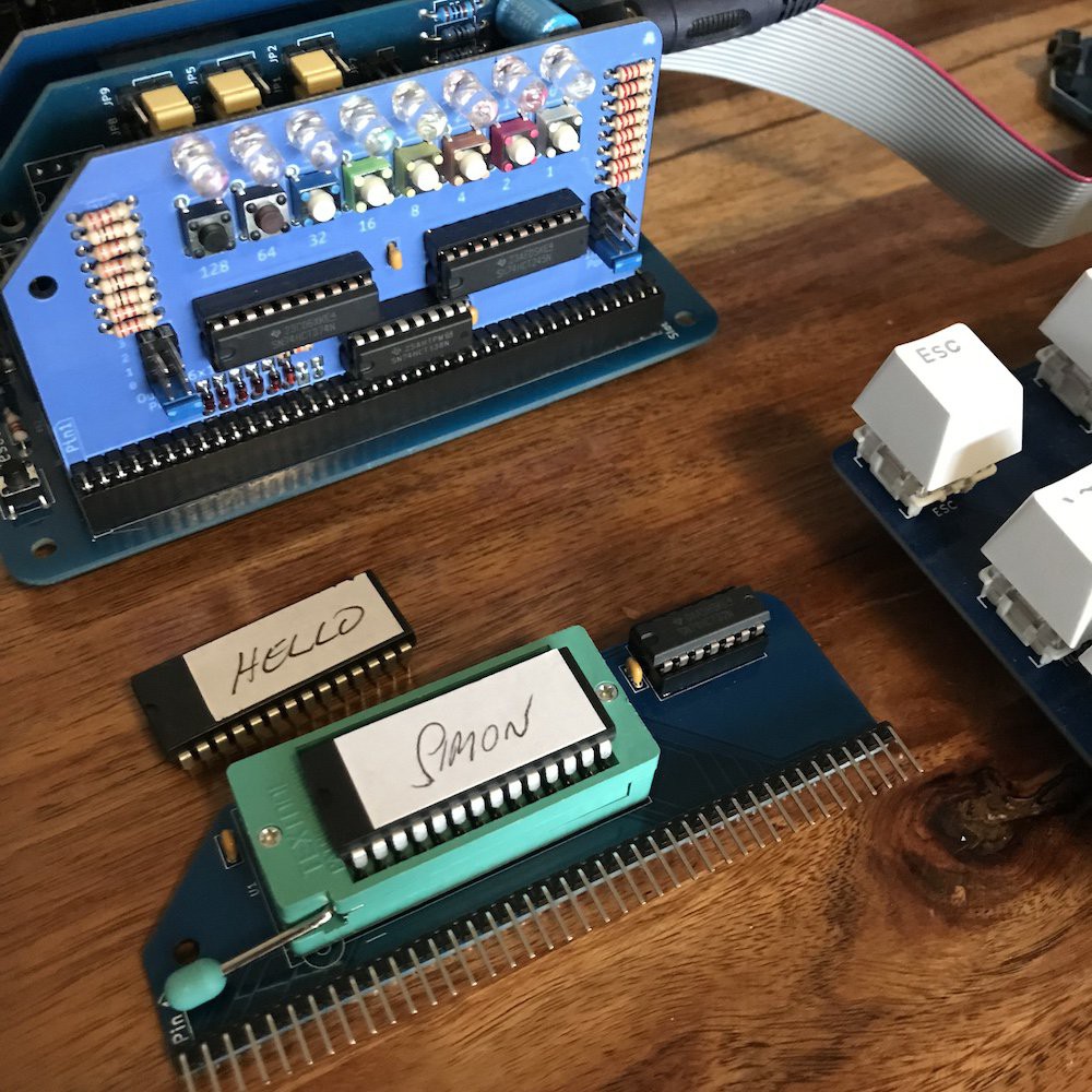
Before that is a demo of my Simon game. I've switched back to the MSX clock speed of 3.58Mhz for that. I'm timing the beeps and animations using a delay, which of course has to be adjusted depending on whether the clock is 7 or 3 Mhz. A better idea is to use the TMS chip for timing which means that games or animations run at a predictable speed regardless of computer clock speed.
This little game looks particularly good on the colourful Pride-edition digital i/o.
* 'template' sounds a bit grand. All you really need is an org $4000 and a 10-byte header:![]()
There's more information about making a cartridge rom in the previous project log.
-
Processes for development
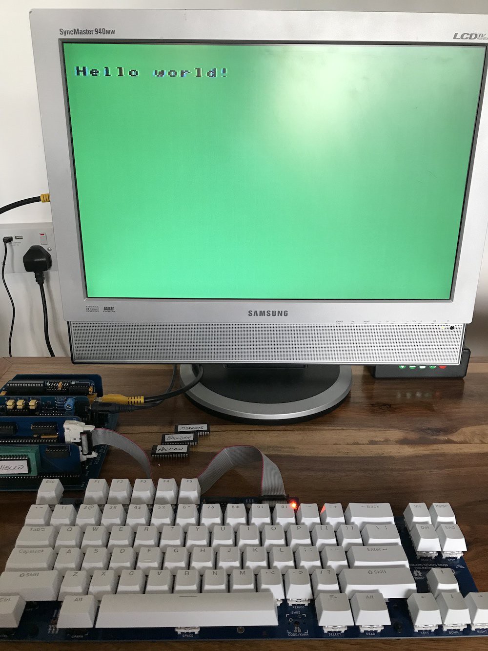
06/23/2023 at 22:28 • 0 comments![]()
This may look underwhelming but it took a while to get here and I count it as a big win.
Obviously I could have typed a few lines of BASIC to do this. Now that I can save to cassette or, more conveniently, my phone (see the last log), development in BASIC is sorted and that has its place.
But how about working in Z80 assembly and making a cartridge ROM or .cas file? I haven't yet investigated what tools are available for assembling directly on the machine, but for practical reasons I'd like to use my favourite text editor and assembler on my modern machine. But how about transferring that to the real hardware?
One option is to make a .cas file. I don't know how to make a .cas image yet, but I've been using a tool called MCP to convert downloaded .cas images to .wav. It's easy to drop that onto my phone and load that into the computer via the tape interface. I do have a tzxduino, which I've upgraded to maxduino firmware, which can play .cas files from SD card - very convenient. I believe that will work, but it seems to be playing at the wrong baud rate and I'm having trouble accessing the menus on my particular device to alter it.
Another option is to assemble my code to .rom, burn to a rom chip and slip it into the zif socket on my 'cartridge module', which is what you can see in the picture above.
This may sound clunky but it works very well indeed, you can see the procedure in the video below. A particularly nice aspect is that you can simply drag and drop the built image onto an emulator while developing/testing before going to the trouble of burning to the eeprom.
It took a while to get to the point of building that rom image. There are a few things to know. I'd sussed most of them out before finding this video which explains everything and filled in the odd gap for me.
Here are a few pointers in case you're doing this:
- at $4000 there should be a 16-byte header, as described here. There's an id at the start and then a pair of bytes gives the 'main' address of your program, often $4010
- it's necessary to pad your program to a total of $C000 for emulators to recognise the binary as a cartridge rom. an 'org $C000' at the end of your code should do it
- The BIOS contains some useful stuff, eg setting screen mode and outputting characters.
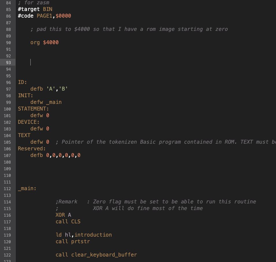
If you're interested in getting started, my 'hello world' is here
-
More tape shenanigans and a great storage solution
06/10/2023 at 18:10 • 0 commentsIn my last log I thought I had a working tape interface. In fact it has taken a little bit more messing about in order to be able to save and load reliably.
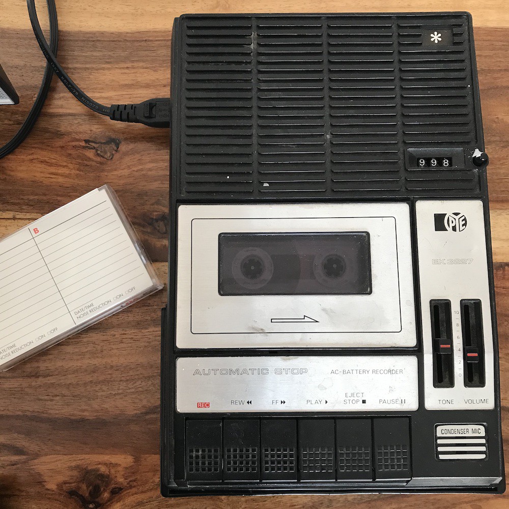
I have a couple of tape players. I've had to replace a stretched belt in this one (a car boot sale find) but it now works really well. The record and playback levels seem perfect and the counter works perfectly too (it could still use a clean).
![]()
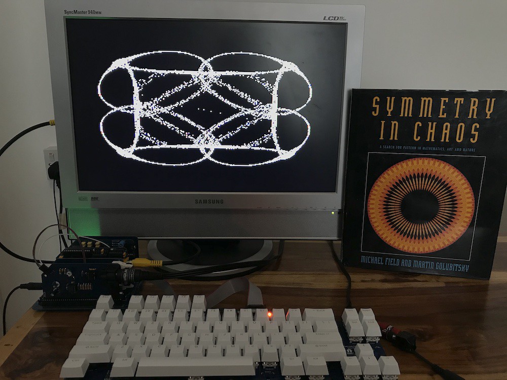
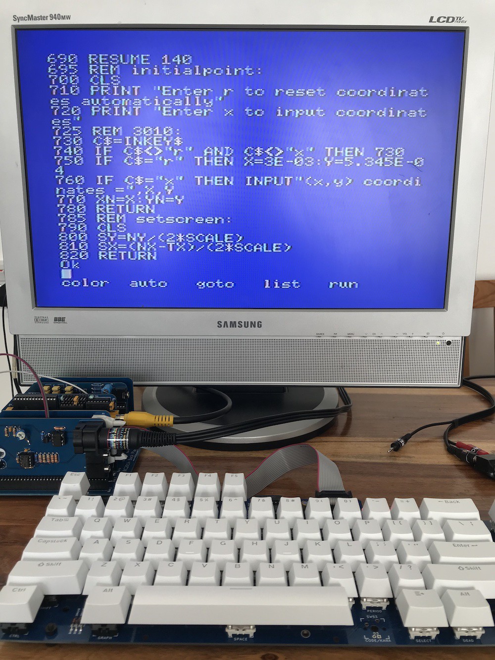
With reliable csaving and cloading, I've been trying some BASIC development of my own plus a type-in from this book:
![]()
It's a brilliant book, all about the amazing patterns you can get from a bit of maths and it has some type-ins at the end. These are written in QuickBASIC and I assumed they'd need a lot of translation but I'm amazed to discover that they can almost be typed in directly (with the addition of line numbers and taking care of variables that start with the same first two characters). I'm only just getting familiar with MSX basic but some of the unfamiliar commands in these programs such as DEFDBL, PSET, PRINT USING and more are all present in MSX basic.
Having said that, the program doesn't run properly and I've got some debugging to do. I'm also not expecting this to produce a pattern as impressive as the ones in the book, but we'll see.
![]()
Alternatives to tape
Having said that saving to real tape is working reliably now (which is good because the type-in program above is the best part of 100 lines) I've been thinking about better storage solutions. I will investigate MSX floppy interfaces with a view to hooking up a Gotek. In the mean time, I've been thinking about developing a microcontroller-based solution that can sample and play back the signals.
That's become unnecessary since I've tried this and found it to work:
![]()
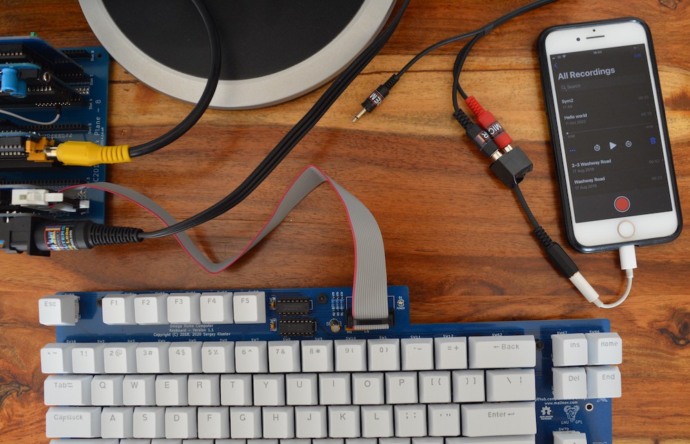
I had to make a 4-pole trrs to 2 x mono jack adaptor, which was very easy and I'll publish instructions for that. (Don't judge my work, I used parts that I had to hand.) I've also had to tweak my interface design a little (technical detail - in order for my phone to detect the presence of a 'microphone' on the lightning connector and use that as an input rather than its own mic, the resistance between the mic and ground connections has to be more than a couple of hundred ohms, I discovered).
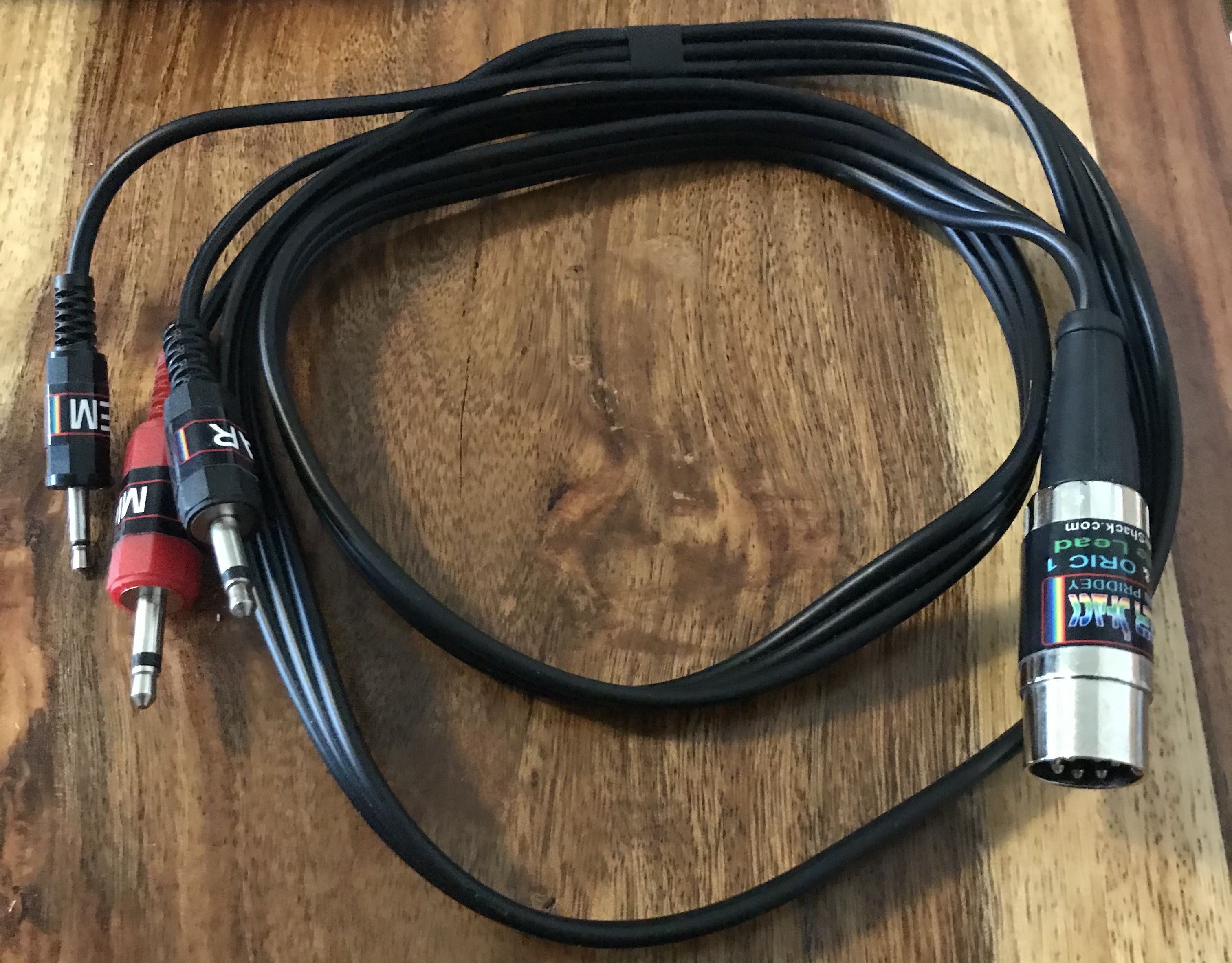
You'll also see that I now have my MSX tape lead (8-pin DIN to mic, ear and rem) thanks to Retro Computer Shack who make fantastic leads.
With all that in place (and with the volume turned well up, which prompts some warnings from the phone's system about the health of your hearing) it works really well. Another important note (as much a reminder for me as to inform anyone else trying this) is that it's important to switch the quality setting for your memo app from 'compressed' to 'lossless'. (Compression will diddle with your nice clean recording and produce artefacts which mess up the data.)
It's brilliant being able to:
- trim any blank space off the start and end of your recordings
- name them
- scroll through your recordings and access them with a tap
- see the save date and time
Obviously we're still saving and loading at tape speed* and have lost the 'rem' functionality (casette motor switch - I'm managing fine without it so far) but I'm thinking that I might even prefer this to a floppy emulator.
* I haven't yet tried the double-speed 2400 baud that the MSX offers yet, but I will.
-
Tape saving and loading
06/05/2023 at 19:36 • 0 commentsIt's rare that a PCB is perfect on the first go. In the case of my PPI module, this is the third set of 5 boards and we're into minor improvements now.
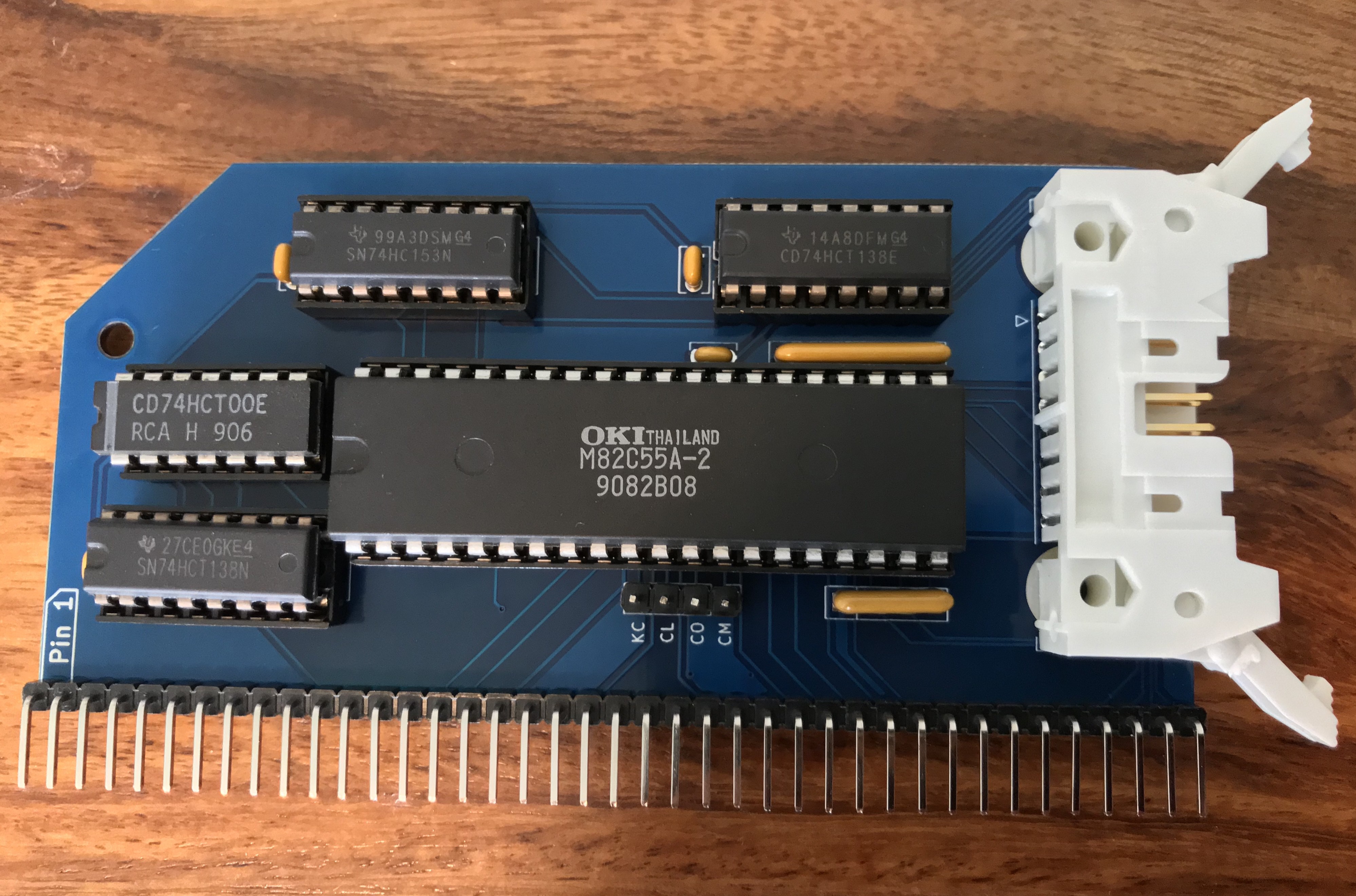
![]()
It's nicely refined now. I've gone for a latching connector. It's essential - not for latching the plug but for extracting it. The 'box' type are fine if you want the plug in there permanently! I've been working on two keyboard solutions and therefore have been swopping.
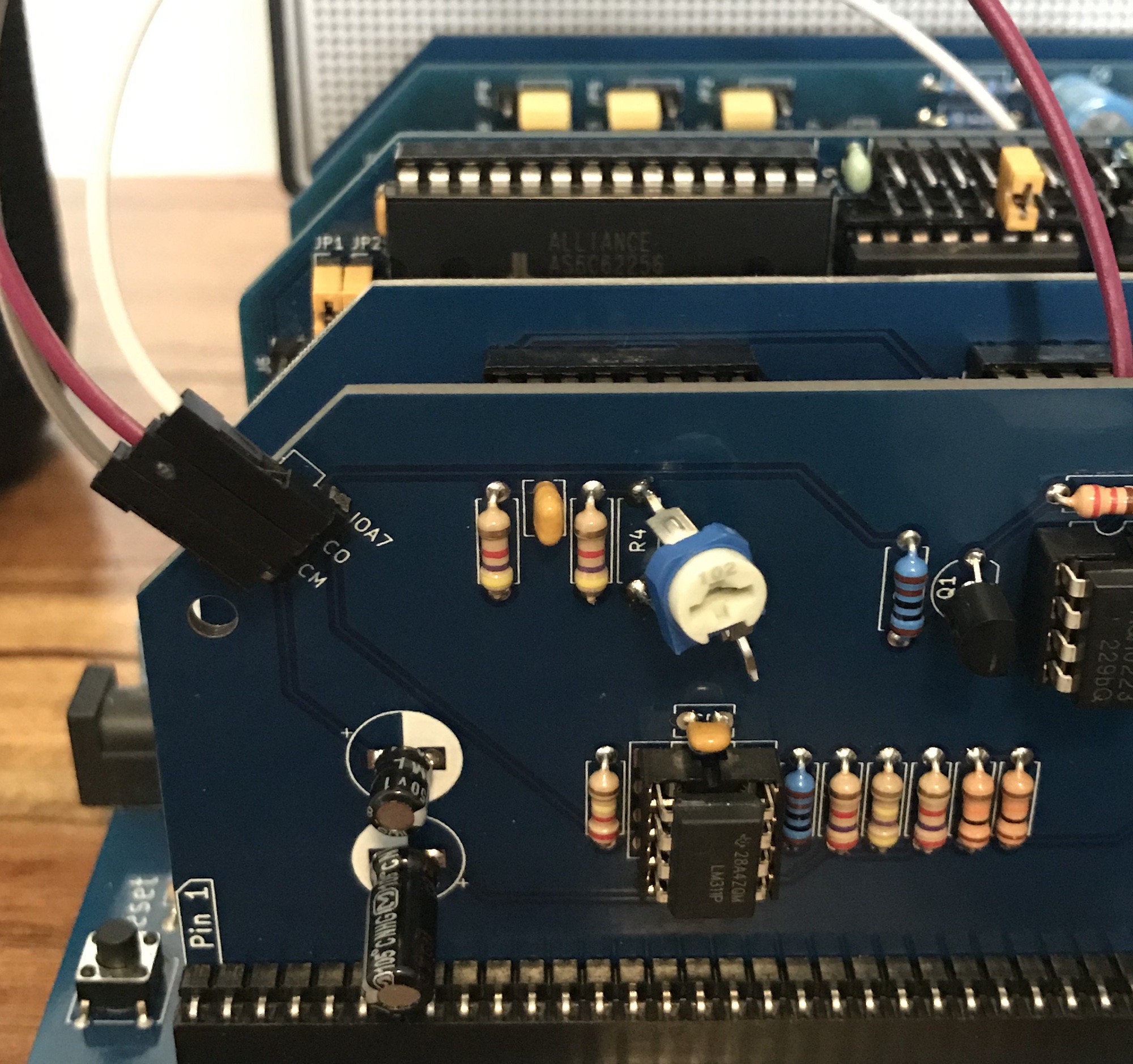
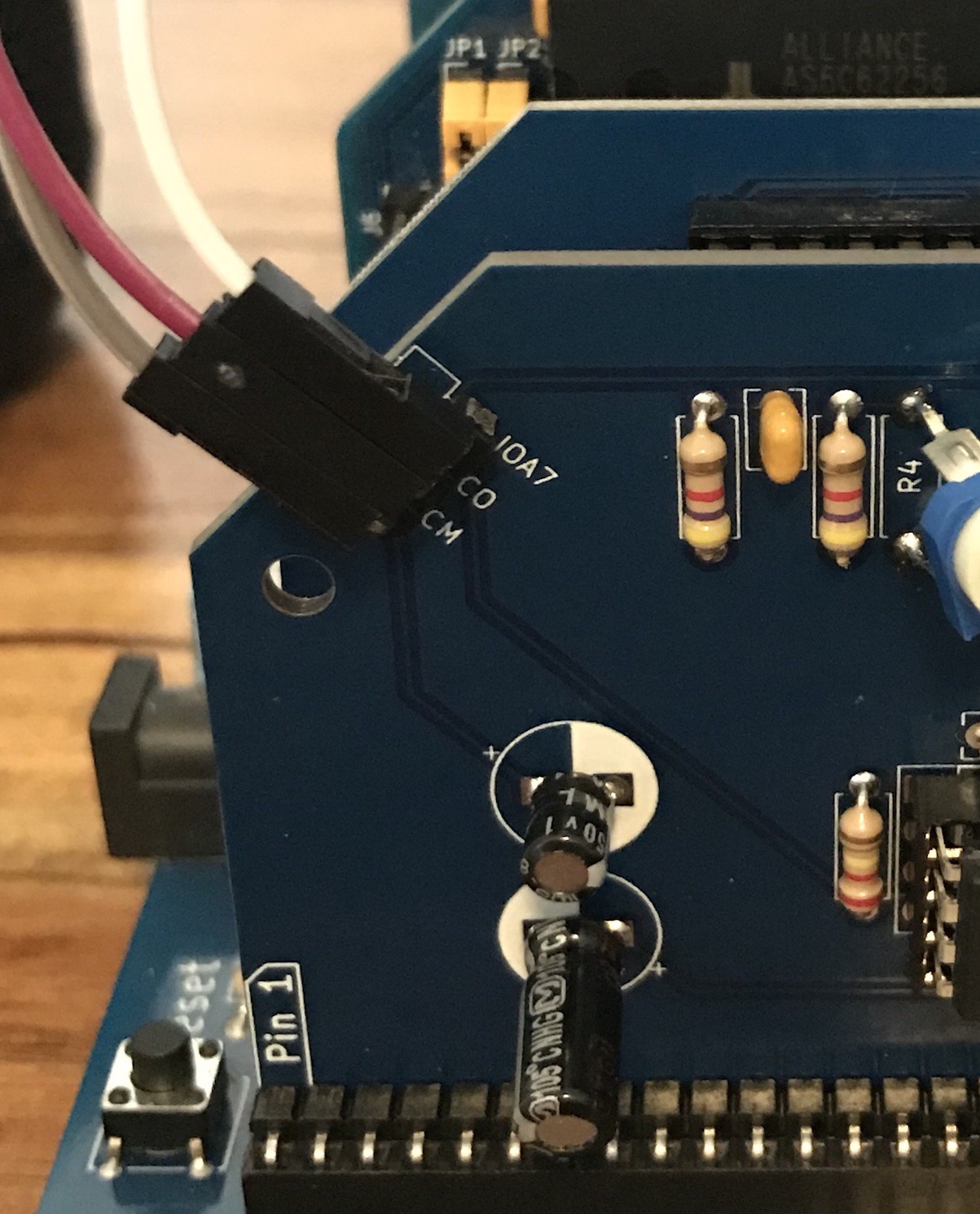
I've added resistor arrays (pullups for the keyboard columns). Previously I had those on my keyboard interface but the Omega keyboard doesn't have them, so it seems sensible to move them to this end of the deal. There's one more improvement I may make yet - note those header pins labelled CO and CM.
![]()
There's not much more to say about this module, it works just as well as the previous version. I really like the look of the latching connector.
Tape module
The second significant thing to report today is that my tape interface has moved off the breadboard and onto a pcb.
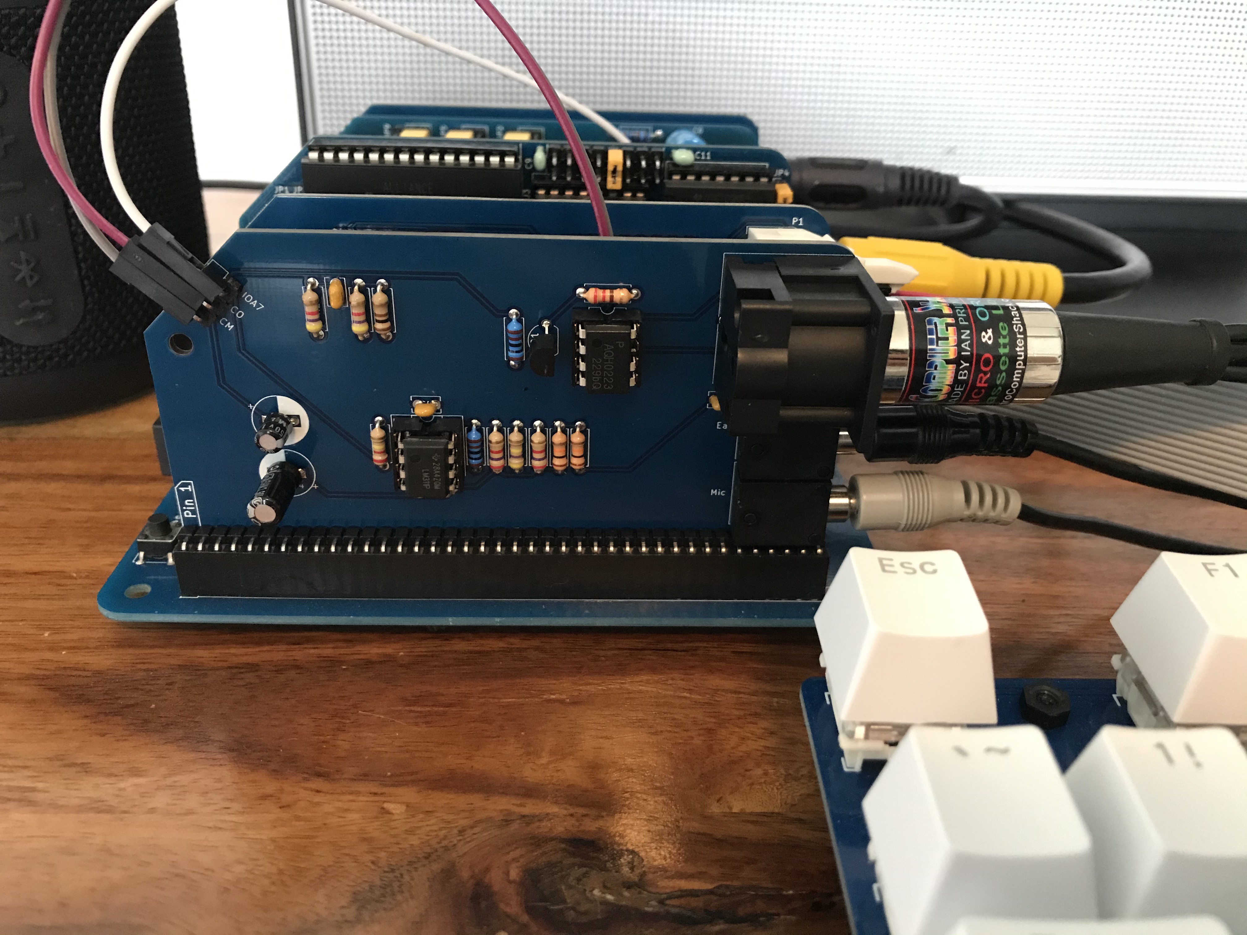
![]()
When I say 'moved off the breadboard', I had only built the input part of the circuit on the breadboard. Here we have the output signal and the remote (cassette motor) switch as well. (I've used an SSR for that.)
I've put the standard MSX 8-pin DIN on there and also the possibly more traditional 'mic' and 'ear' audio jacks. For the sake of the picture I've plugged them all in, but obviously you'd use one or the other.
Nostalgia for cassette loading?
If I wanted to re-experience the 'joys' of sketchy tape loading, boy I've had that today. I don't know how many times I've pressed 'play' on the tape and watched the screen hopefully but in vain.
Initially I had nothing. Here are the problems I've found and fixed, roughly in chronological order.
![]()
This is the lead I was trying to use at first. It breaks out the 8-pin DIN to ear, mic and rem jacks. This is the one I use for the Oric, BBC and Electron. I may have given the pinout a quick look or I may have assumed that the pinout is the same for the MSX. They were trying to establish a standard after all. But it turns out they're not quite the same. The MSX standard (which I worked to with my module) is almost the same but slightly different. Why would they do that??
Not a big deal. I found this issue easily and have an MSX-compatible lead on the way from Retro Computing Shack. Plus I put ear and mic jacks on my module, so I can use those in the mean time.
But I couldn't make those work either. My breadboard circuit worked great for loading from real tape. My new module should have been exactly the same circuit but just seemed dead.
After much time spent checking the resistor values (check the picture above, there are so many different values on that board!) I eventually noticed an error with my schematic. I'd worked from the reference circuit when building the breadboard version and worked from the same reference circuit to make my schematic. Except that i had missed two important connections - the op-amp's v- and ground, both of which are tied to 0v in this case.
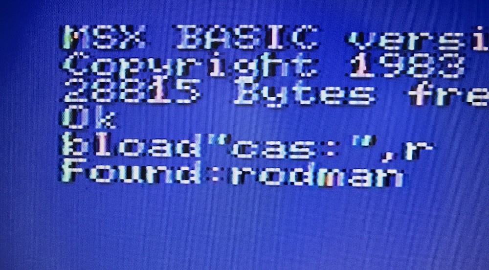
Two bodge wires later and we can load from a pre-recorded cassette (the only one I own for MSX!)
![]()
Saving went more smoothly, or at least appeared to at first.
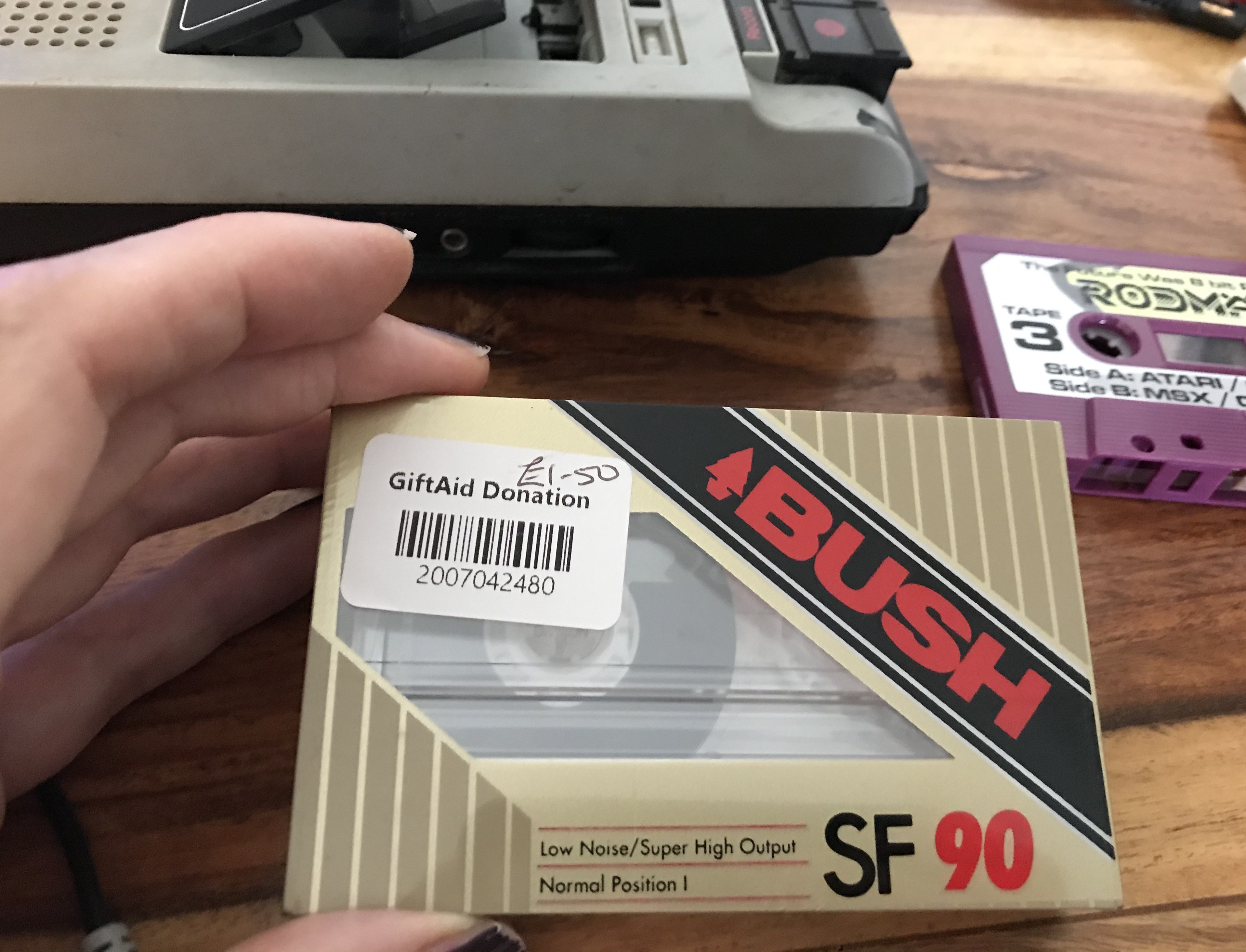
I had found this unopened blank tape in a charity shop about a year ago.
![]()
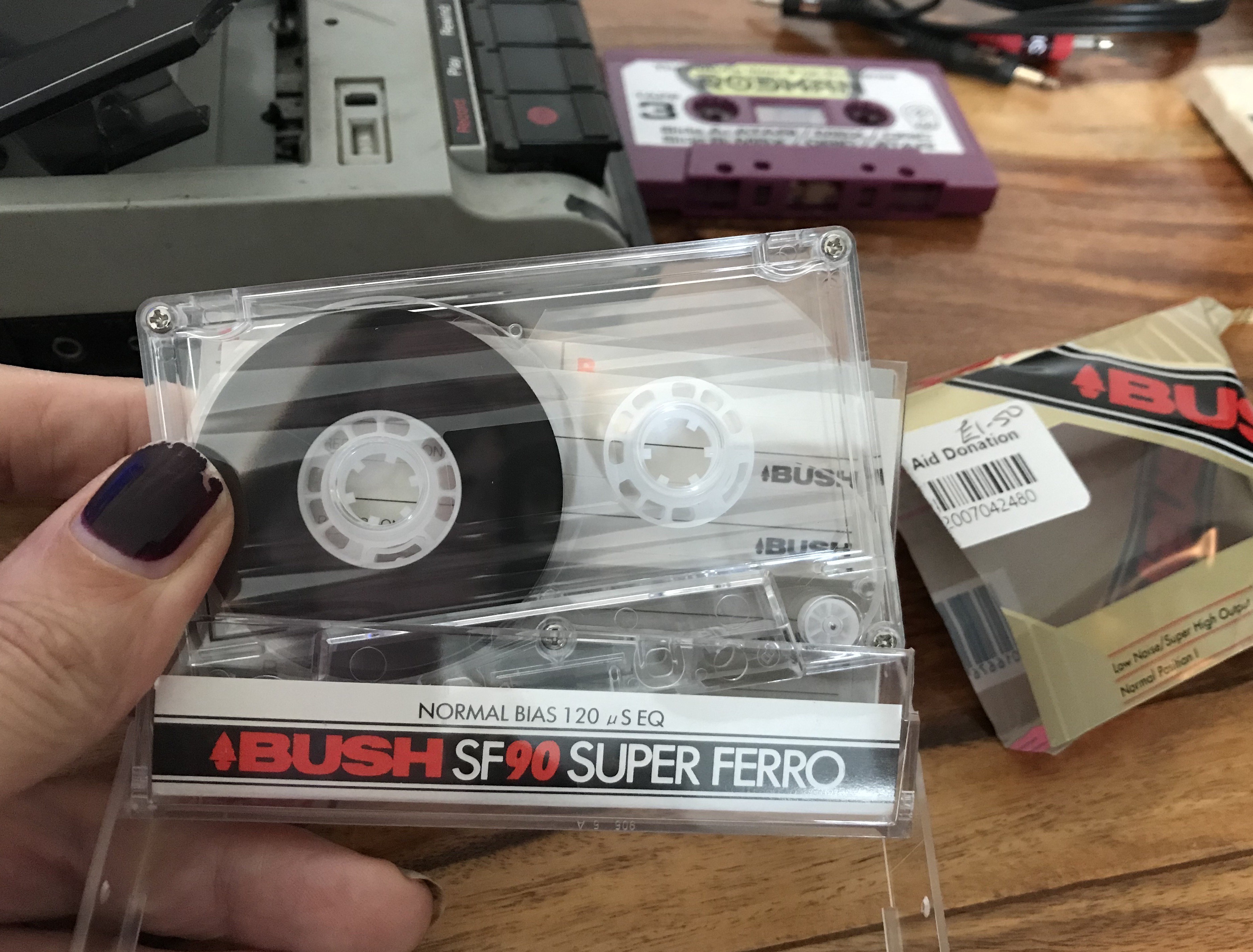
This seemed like the perfect time to crack it open!
![]()
It appeared that my test program had saved successfully, I could listen back and it sounded pretty crisp.
But the computer wasn't recognising my saved programs. It would still load the commercial tape, so I assumed that it had to do with levels and spent waaaay too long trying different levels and two cassette players.
Eventually I tried capturing the sound using a modern computer. This allowed me to view the waveform and see that the output signal was *really* puny.
By amplifying it up ( several times its original amplitude) I was able to load that back in.
The output circuit is much simpler than the input. The TTL signal from the PPI pretty much goes out to the mic jack, with some filtering and a voltage divider in between.
I had noticed that one of the values in the reference circuit looked very questionable. (Though the Omega project uses that same reference circuit with the same values.) I bodged a trimpot in its place so that I could experiment. This effectively gives me an 'output level' control which I think I might add to my design.
![]()
Still using the modern computer to capture the output, I was able to adjust that to a much more promising-looking level and eventually load that straight back in without amplifying it digitally.
![]()
... and here's the first time I was able to save a program out to tape and load it right back in.
So I started out by saying that a board is rarely perfect on the first try. I thought my 'tape module' might be - it's pretty much just a reference circuit after all. But that's a long way from the truth.
I must fix the connections I missed. The 'rem' / cassette motor circuit is different from the reference because I put in an SSR and have yet to test that out properly. (I'll wait until my new lead is here). And a component appears to need to be a very different value than that given; I'll put in a variable one.
![]()
Yes, I need to either look at the footprints for these electrolytics or buy physically larger caps! Preferably matching size. Would it be cheesy to position them on this board so that they look like the spool centres of a cassette??
And the elephant in the room is those connections which go to various other boards. (signal out, signal in and the cassette motor control.) I've run out of spare connections on the standard RC2014 backplane. I'm thinking about using connections on the extended bus for these signals. (with the option of using flying leads like this for when the modules are used on a standard backplane.)
All of this has taken the shine off the experience of unwrapping a 'new' tape and saving / loading my own program. Now that it's working, maybe after a sleep or two I can return to it and enjoy it fully.
-
Tape loading
05/26/2023 at 09:41 • 0 commentsMy original stated goal was to build an MSX1 computer but that's a bit vague. ie I don't really know when I've achieved that goal. What didn't say but always had in mind is that I really wanted to be able to load and play one particular game from tape.
My own nostalgia is for computers that had BASIC on startup and tape saving/loading, so I feel that the tape loading is an essential part of this project.
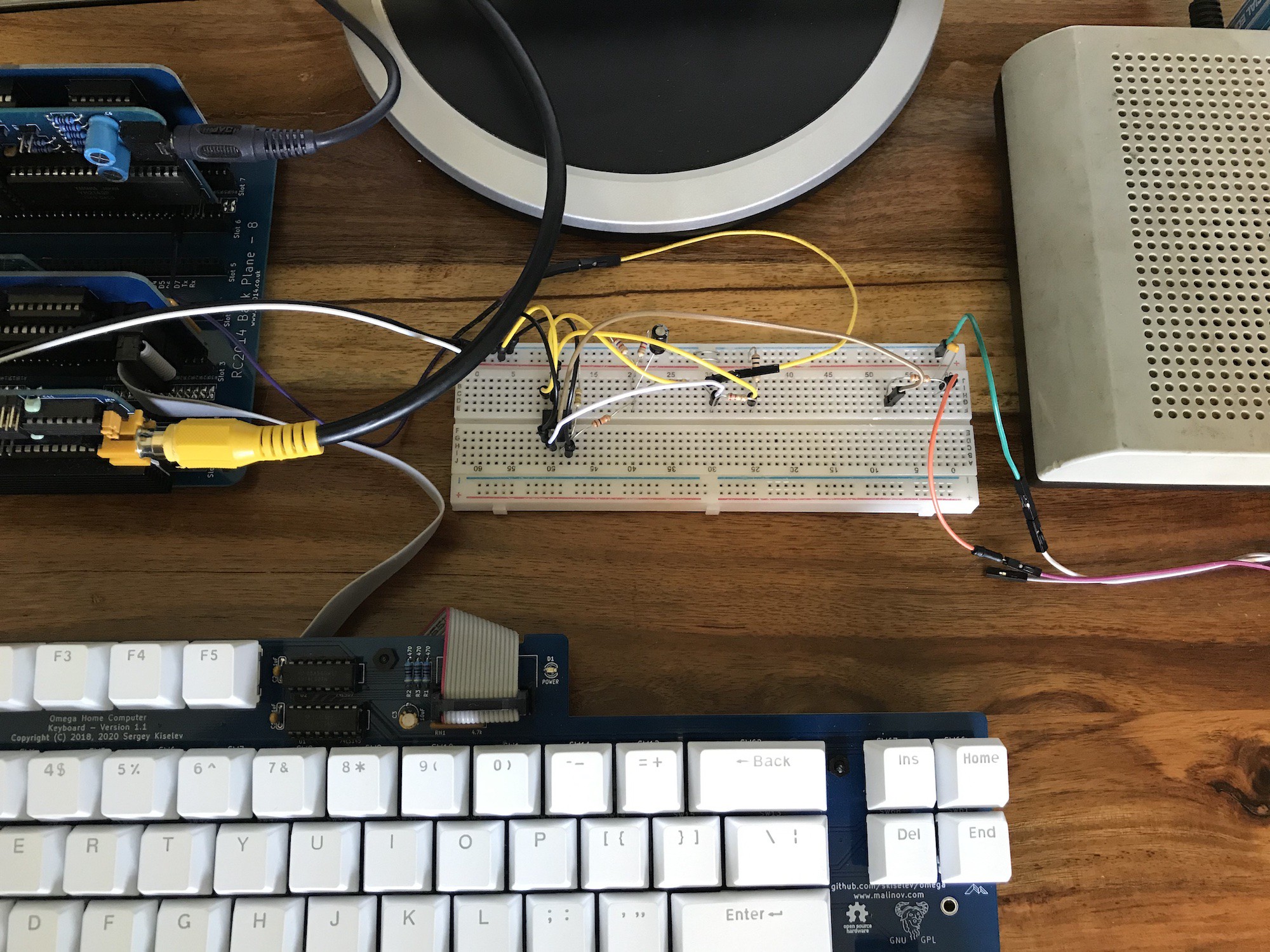
The reference circuit I used has an op-amp to turn an audio signal into a logic signal. Here's the circuit on a breadboard, in which I had very little confidence.
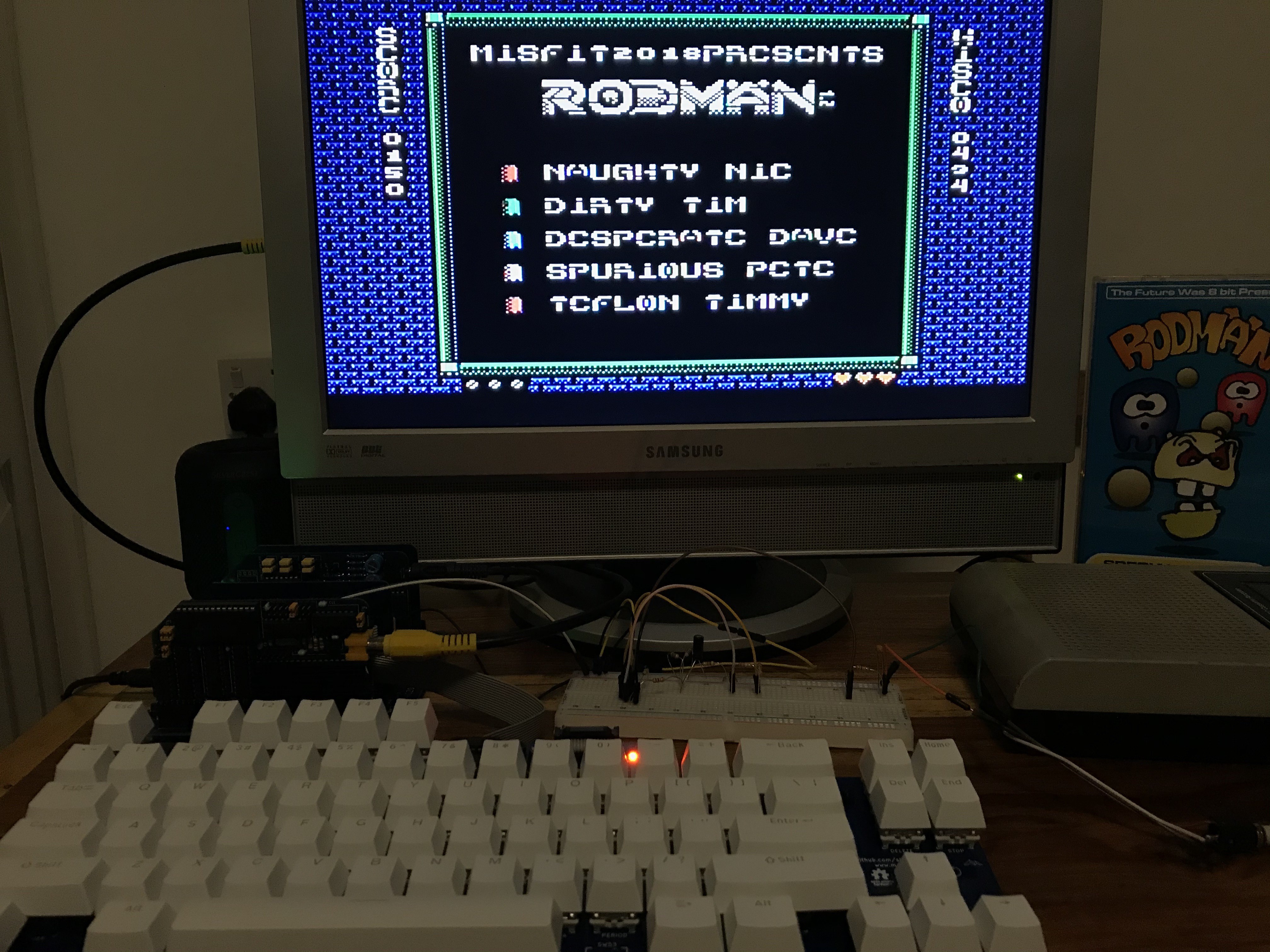
![]()
Imagine my astonishment when the game loaded on the first try....
![]()
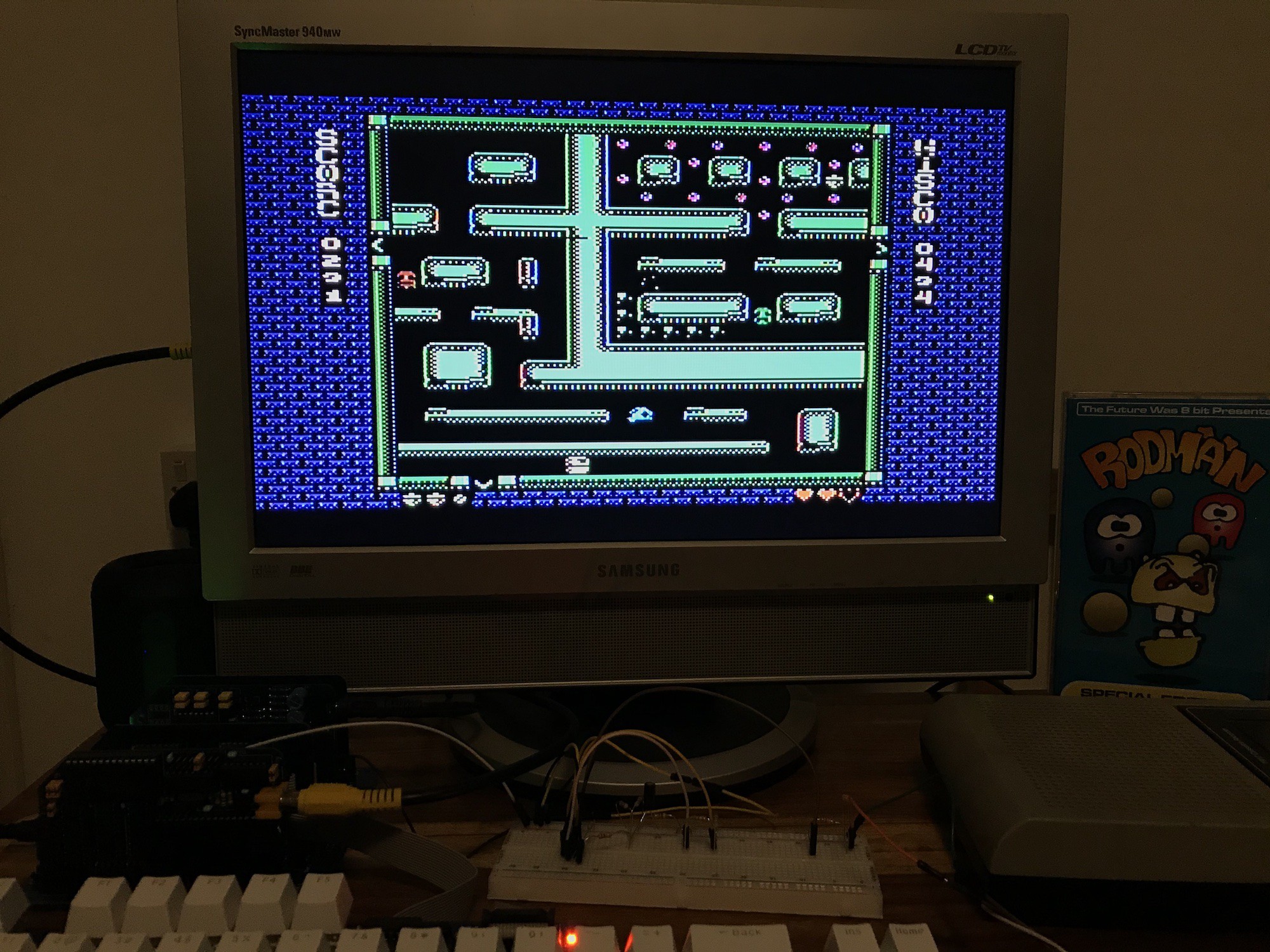
(It's a new-ish game from futurewas8bit on a multiformat tape. Playing it here on my MSX2014 has checked off one more format, leaving just one of the eight to go.)
t's a great game and this MSX version is a particularly good one. It's very addictive and my 'arrow key' hand ached after a while. This is the incentive I need to build the joystick circuit!
![]()
The thing that I'm finding harder than building the working tape and joystick modules is how to organise them and how to connect them.
Electrically it makes some sense to build the tape and joystick modules on one board. But from a user point of view that makes no sense and gets away from the modular nature of this build, so I think they should be separate modules.
But that introduces some problems with connections. The tape interface (assuming we want both loading and saving, which we do) involves one connection to the sound module (because sound chips weirdly also tend to handle some of the i/o) and one connection to the PPI module. The joystick module also needs connections the sound module.
I've already used the spare lines on the bus for the very important slot selection lines. I could use lines on the RC2014 enhanced bus, but I'd like this project to be buildable with the standard backplane.
While I think about that, I'm going to play more Rodman.
-
Some refinements, a first look at MML and a type-in
05/22/2023 at 17:26 • 0 commentsI've been having trouble fitting all of the necessary modules onto a backplane 8 and have had to use a Pro backplane with 12 slots.
I've tried to bodge an RC2014 ext-clock module* onto a Z80 module - it seems a waste to have those two basic things on separate modules. More than one person has designed a combined clock/Z80 module, so I may buy one of those. It doesn't help that some things hog two slots because of sticky-out bits.
One contributory factor to the slot shortage is that the BIOS ROM, RAM and cartridge ROM are separate modules.
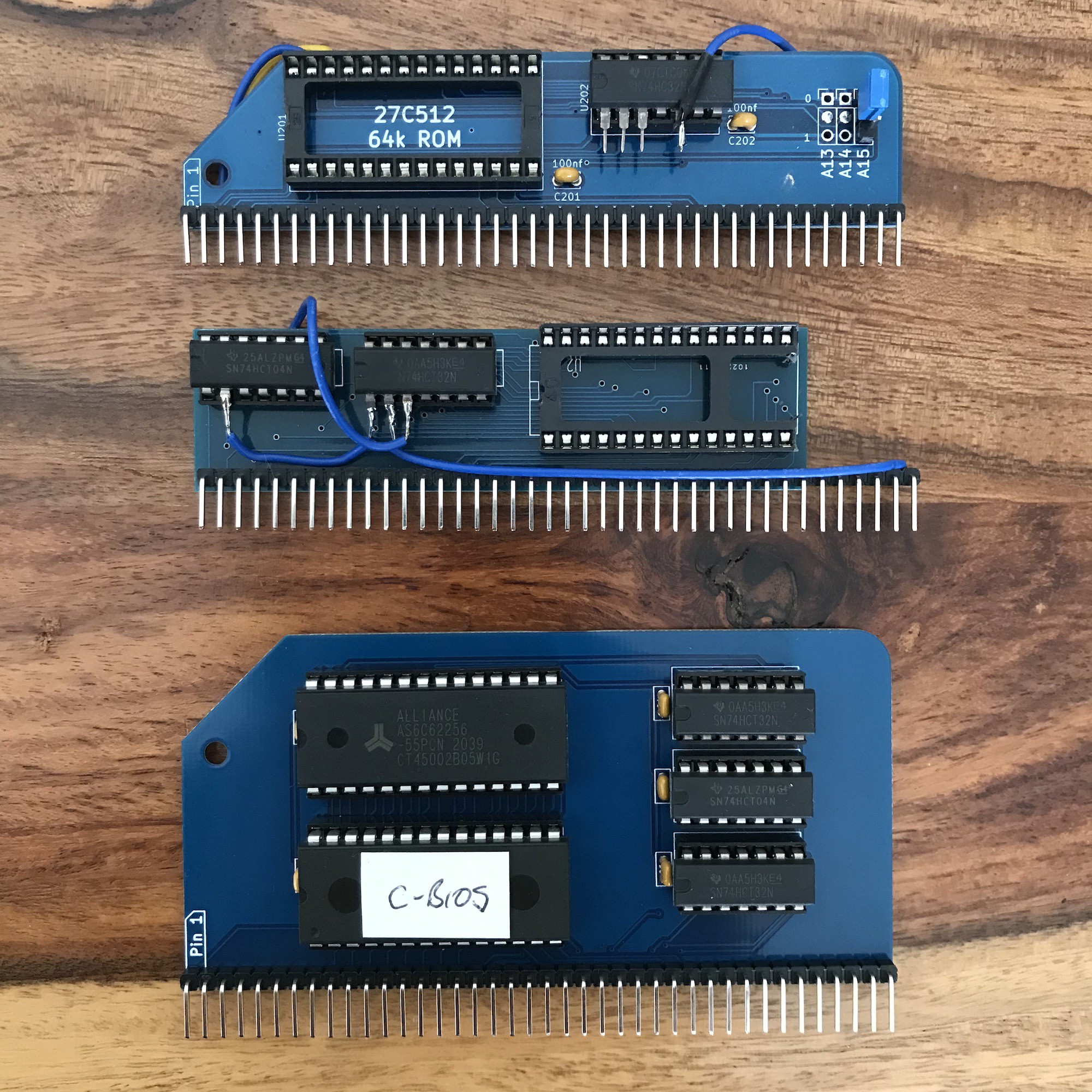
So the first new thing today is a combined RAM / BIOS module.
![]()
It replaces my bodged individual modules with a single nice neat, standard-sized and shaped module. The downside of this is that it gets away from my original goal of "using standard RC2014 components as far as possible". (the c-bios label is out of date. I didn't get that to work and see no point when the original MSX1 bios+BASIC is working so well).
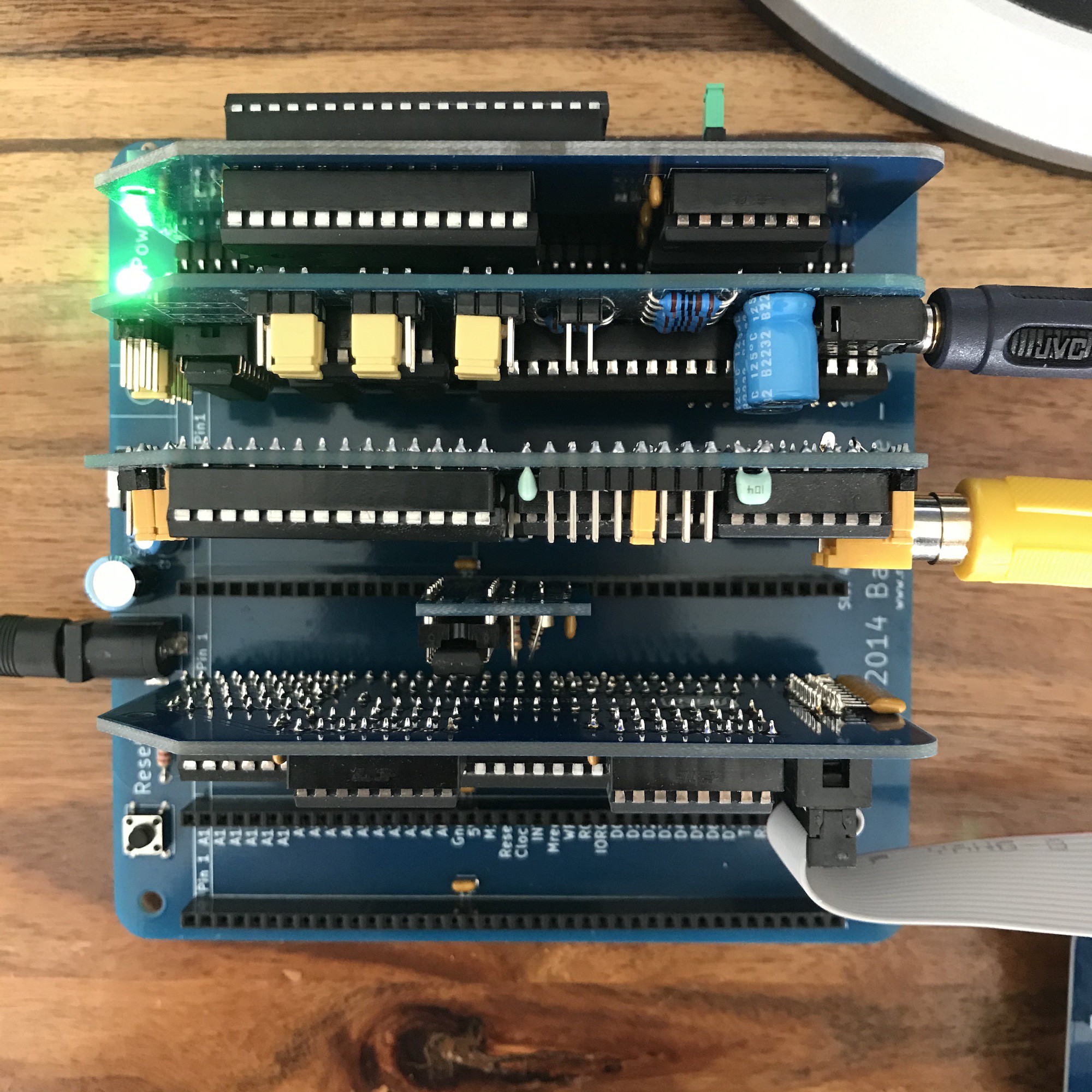
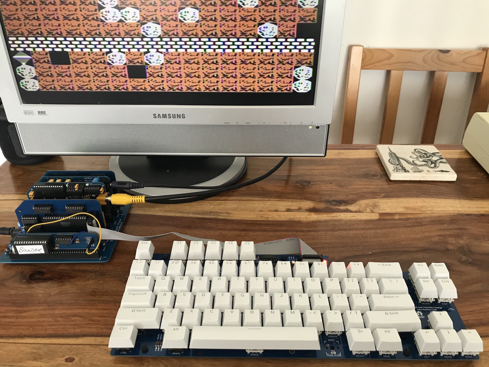
So here are a couple of shots of the machine as it stands, configured to run BASIC. Even with the separate clock* and Z80 modules it all fits neatly onto a standard backplane 8.
![]()
![]()
Composite video isn't fantastic, but it does look better in real life than captured here on my phone's camera.
I can even fit the 'cartridge ROM' onto that backplane. (That's still a bodged RC2014 ROM module.)
![]()
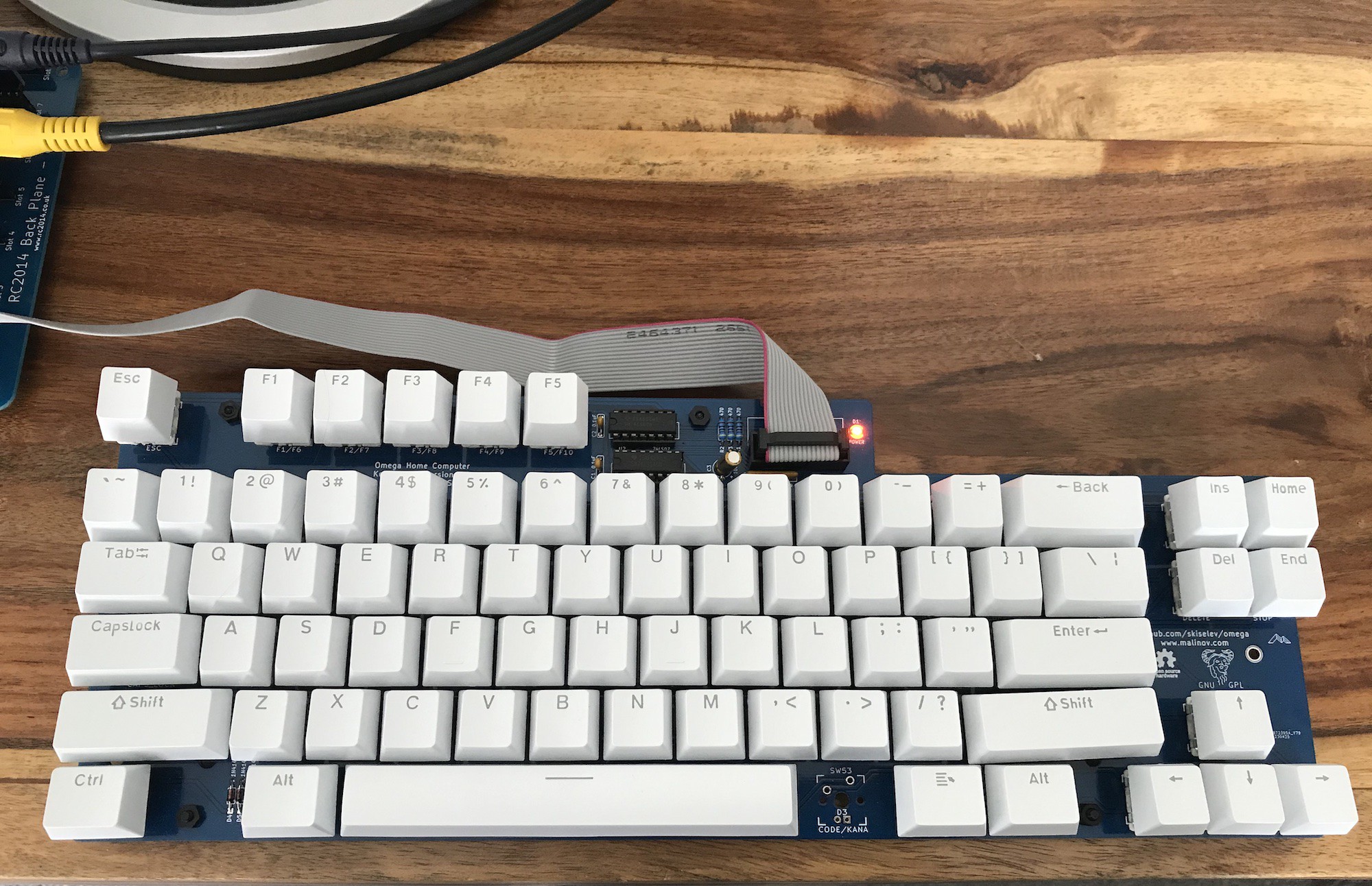
In the shots above you can also see the other refinement. I've now got keycaps on my Omega keyboard, and wow, is it nice to use! I picked up some Gateron swtiches at a great price. It's really fun playing games with it, the inverted T arrow key arrangement works well for me.
![]()
I have yet to add stabilisers. I didn't know anything about mechanical keyboards before making this one, it's a bit of a learning curve. But even without those, the longer keys actually work pretty well, even the space bar. My very cheap set of keycaps worked almost perfectly - the @ is in the correct place on the 2. There's even a keycap (to the right of the spacebar) with a symbol that works perfectly for the MSX 'select' key (an important key). All of this without a key having to be on the wrong row for its profile. Great work from the Omega project.
MML
Ed Brindley, the maker of the YM/AY sound module for RC2014 (an important part of this project as it handles some of the i/o as well as the sound) mentioned to me that MML (Music Macro Language) was a bit of a rabbit hole.
It's a notation system for music and is supported by MSX BASIC. The musical notes and other information are contained in strings, which you pass to the PLAY command. It allows for multiple voices and gives you access to the AY's envelope system (which isn't fantastic but does allow for some rudimentary FM experimentation).
I've had a look around for tutorials, and I found some good information in Graham Bland's book, MSX Programming. Obviously the examples have to be typed and so what better way to test my new keyboard?!
There's quite a long example (program 7.10 on page 112 in the book) and so I made a cup of tea and got started!
I video'd the whole thing. Fortunately the camera kept rolling for the whole half hour and the result is not as disappointing as you might expect a type-in program to be.
This may be the most boring video on Youtube if you're not interested in MML or MSX BASIC, but here it stands as a record of my first real test of the Omega keyboard and MSX BASIC's MML capabilities.
* The RC2014 dual-clock module is great for this project because it allows you to jumper the clock to 3.68 Mhz which is very close to the MSX standard 3.58, plus you can switch to 7.3 Mhz to give MSX BASIC a real boost. For perfect compatibility I've made myself a 3.58 Mhz clock module on a spare RC2014 ext-clock board and tend to use that cor compatibility / authenticity.
MSX on RC2014
in which I attempt to make an MSX1 compatible computer using RC2014, keeping to standard RC2014 backplane and modules as far as possible.


