Dr. Cockroach
-
Urgently need funds for replacing my car
10/09/2017 at 15:05 • 4 commentshttps://www.gofundme.com/srntge-replacement-car-fund
The above link is to help generate funds to replace my car. I was in a accident on Sept 30, 2017 and thankfully I am OK as was the other party involved. However I have been informed that my car is totaled :-) The insurance companies are dragging their heels and I need to get something that is safe to drive. My car does drive but not very well. My wife, Stephanie Young posted the funding page.
Thank you for any help :-)
![]()
The first donation today, Thank You :-)
November 8, 2017. I am very happy to report that A local donor has given me a car for free and the funds that were donated took care of the Tag and Title costs so a big THANK YOU to those who helped me out :-)
-
October 4, 2017 - Brainwarp read logic hardware
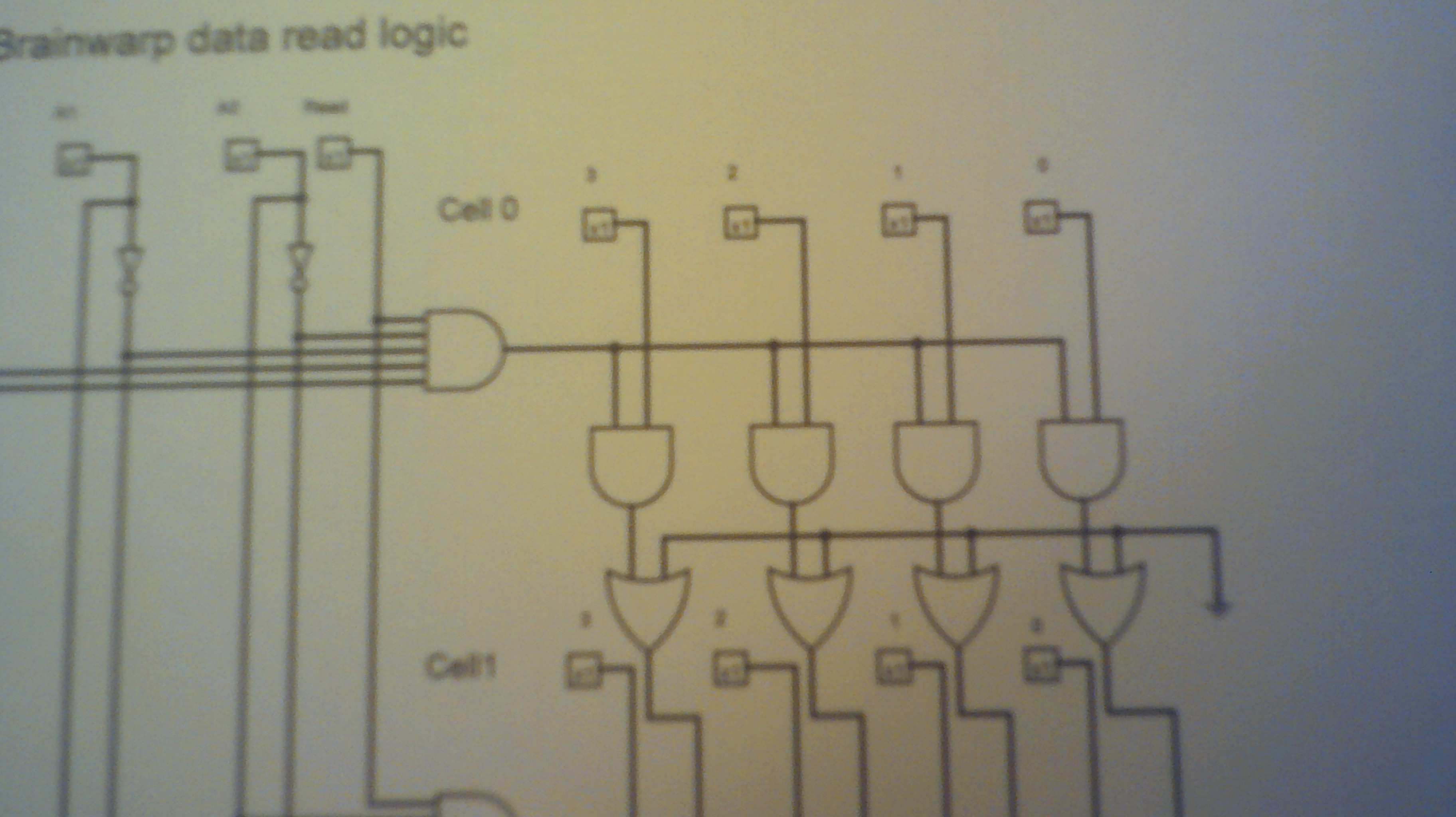
10/04/2017 at 22:12 • 0 commentsIt is at last time to get cracking and work on the read logic for Brainwarp. The plan is to use my typical Nand / Not logic circuits and the following images should give everyone the idea of how much wiring this will take for reading up to 15 Brainwarp instructions. Remember that it will be one entire board for each card position on the Brainwarp panel.
This is the Logisim circuit that I will use.
![]()
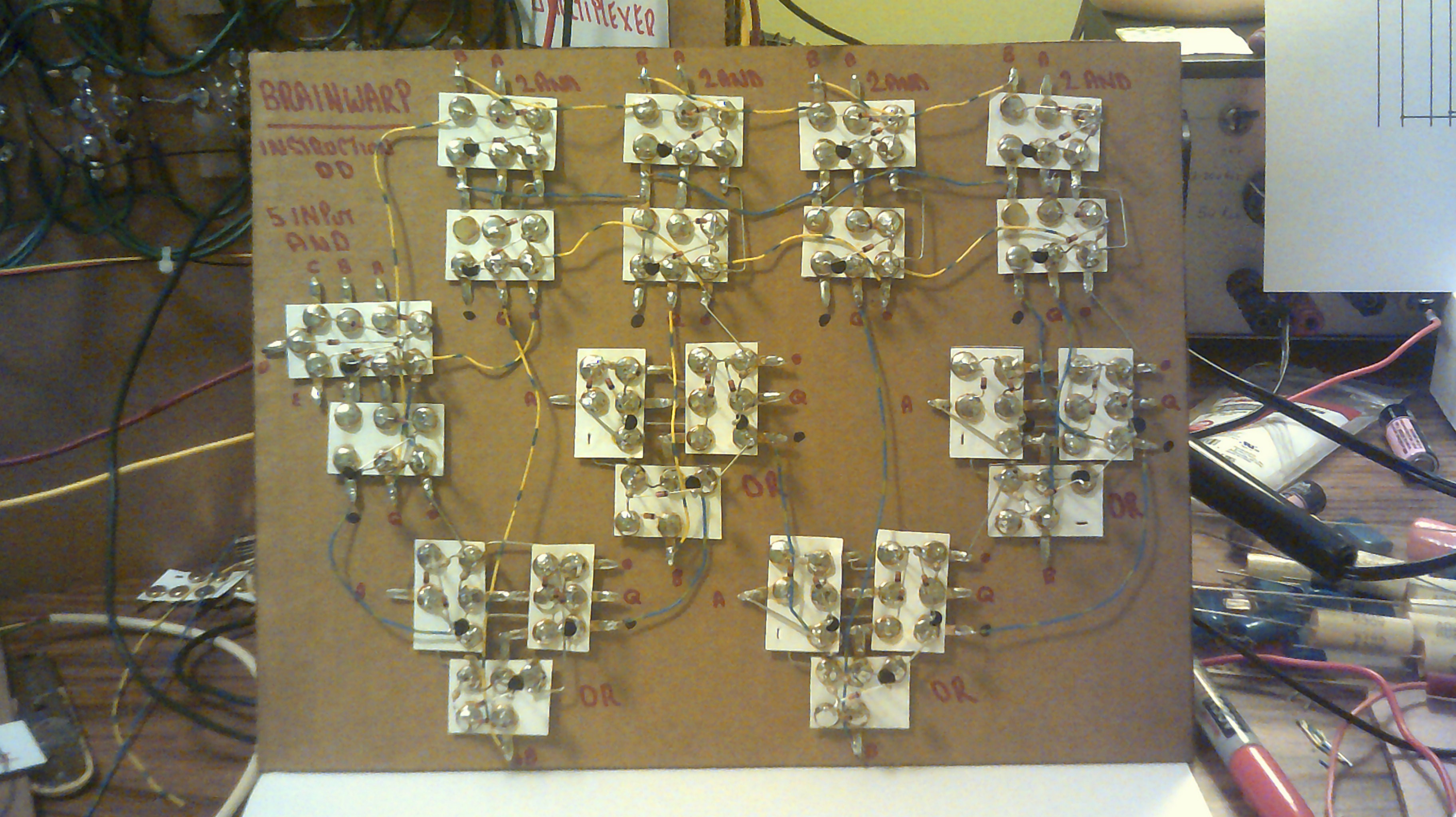
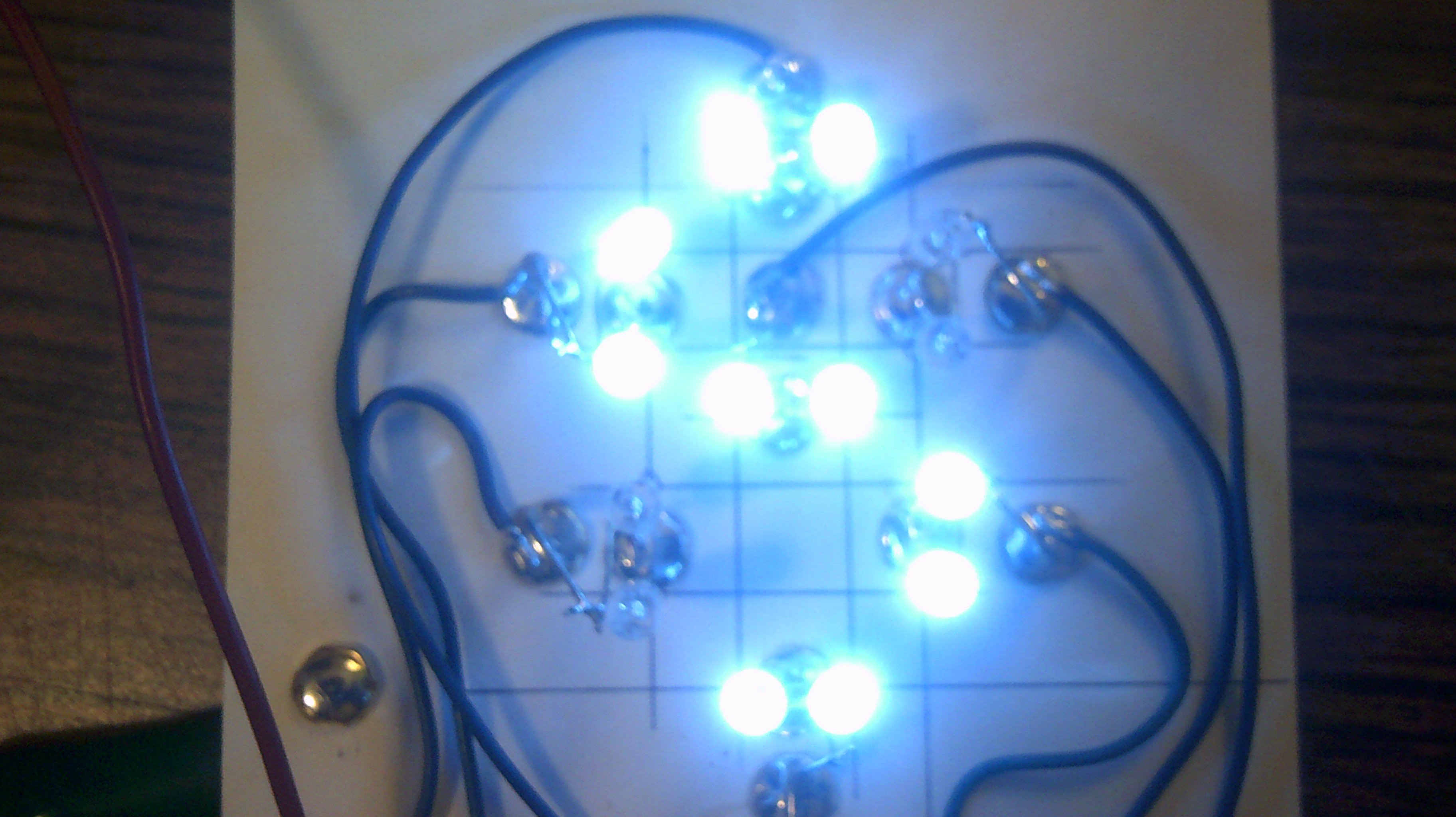
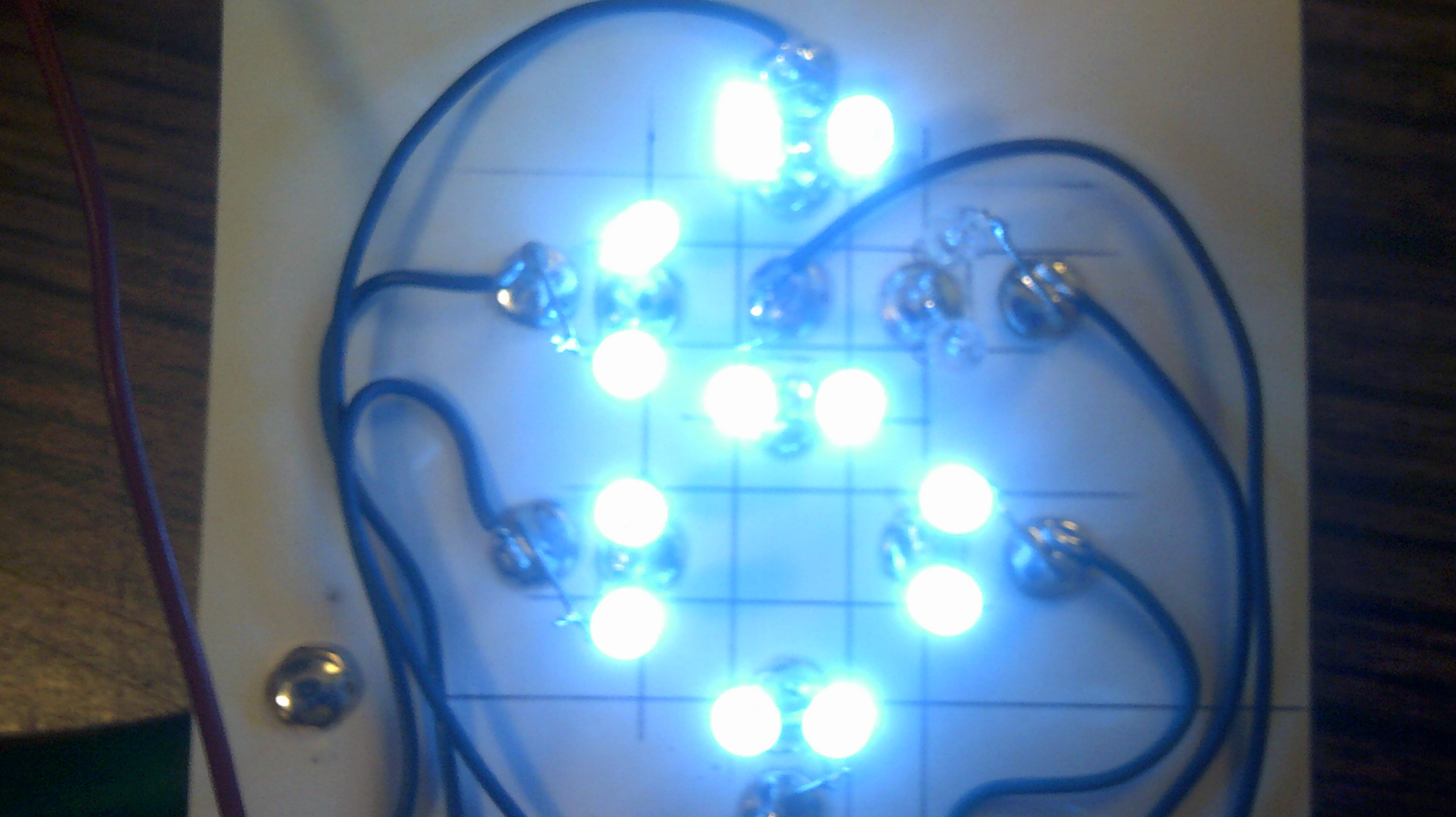
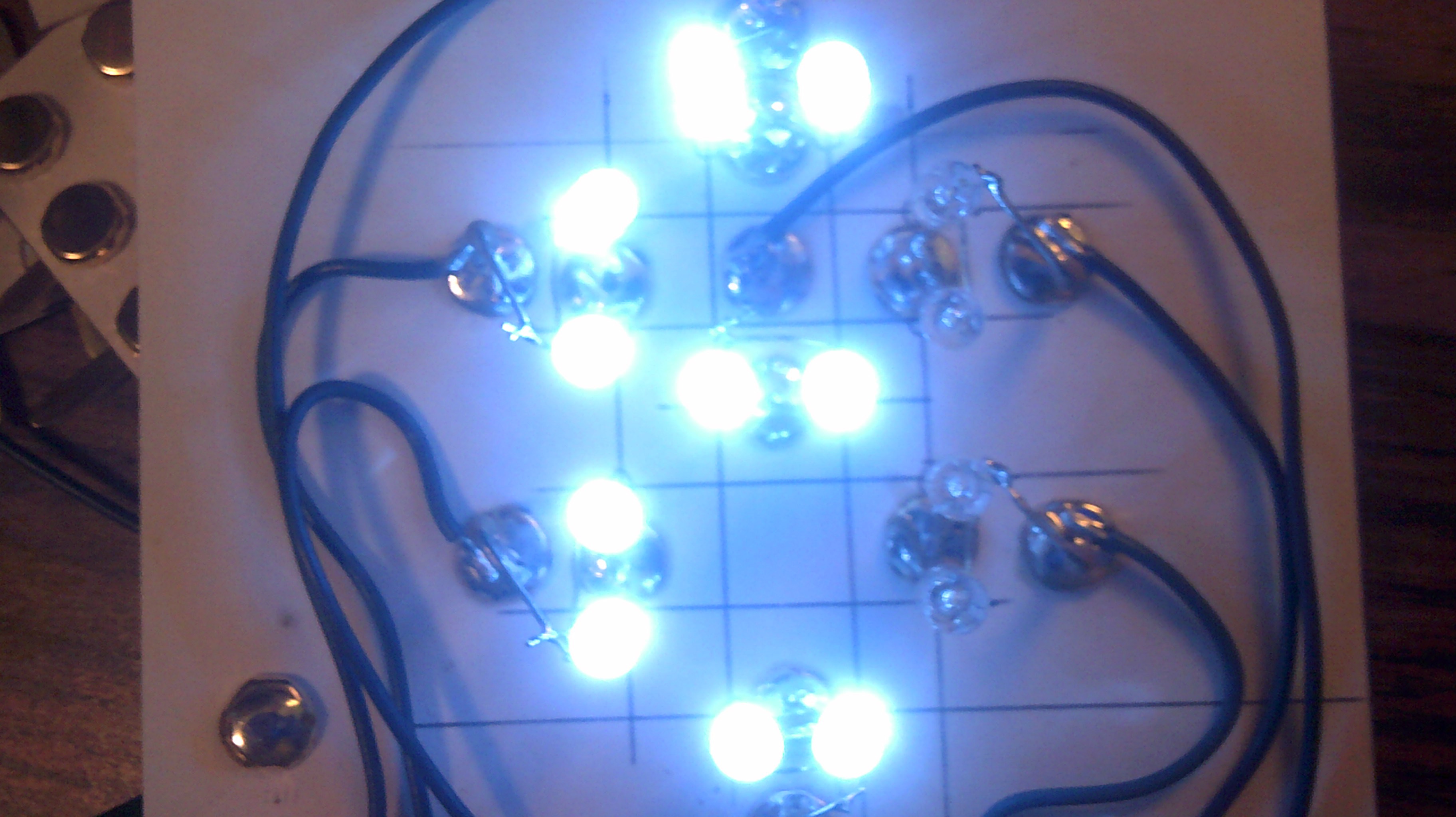
The board layout required for each of Brainwarps 15 instruction locations.
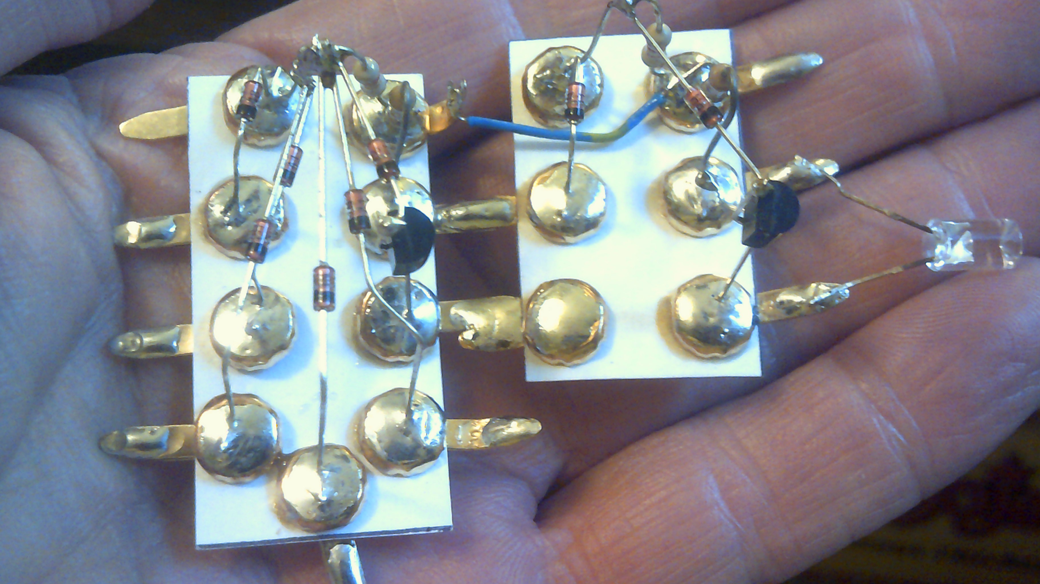
![]() This is the 5 input And gate using a Nand and Not gate. Led is the output side.
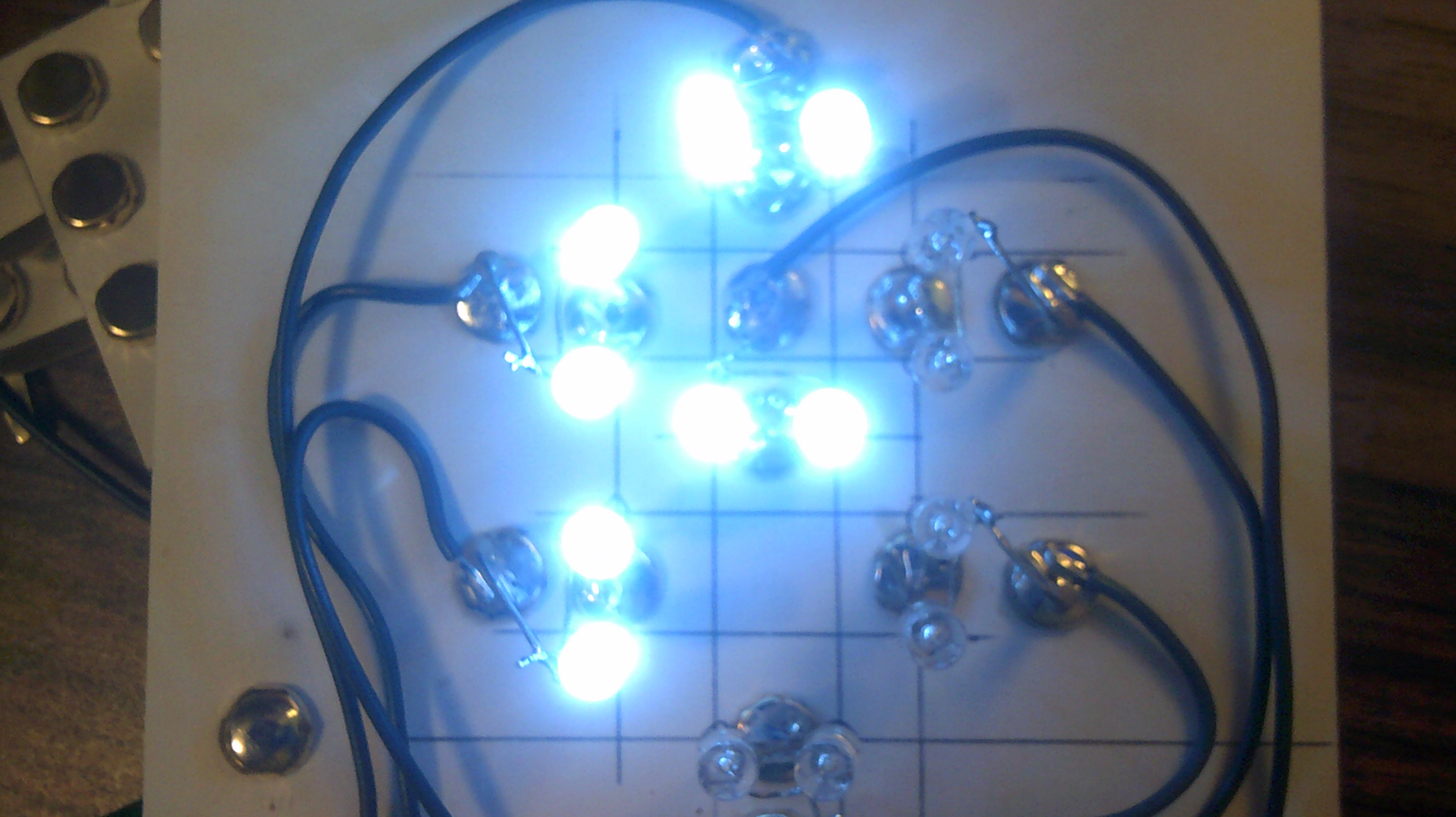
This is the 5 input And gate using a Nand and Not gate. Led is the output side.![]()
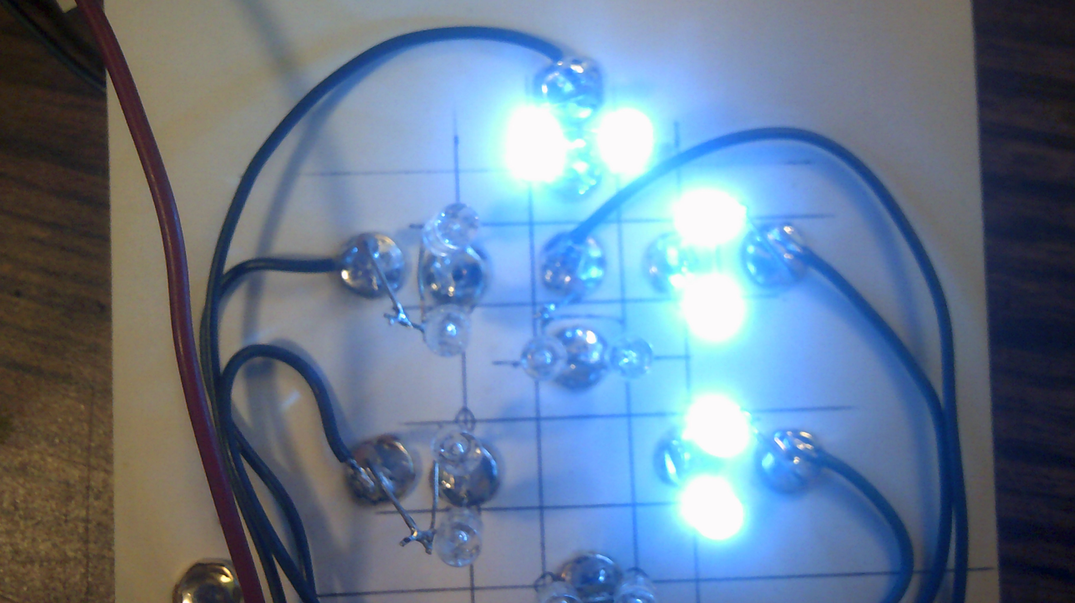
This how I can make And & Or gate modules. There is lots of room for improvement.
![]()
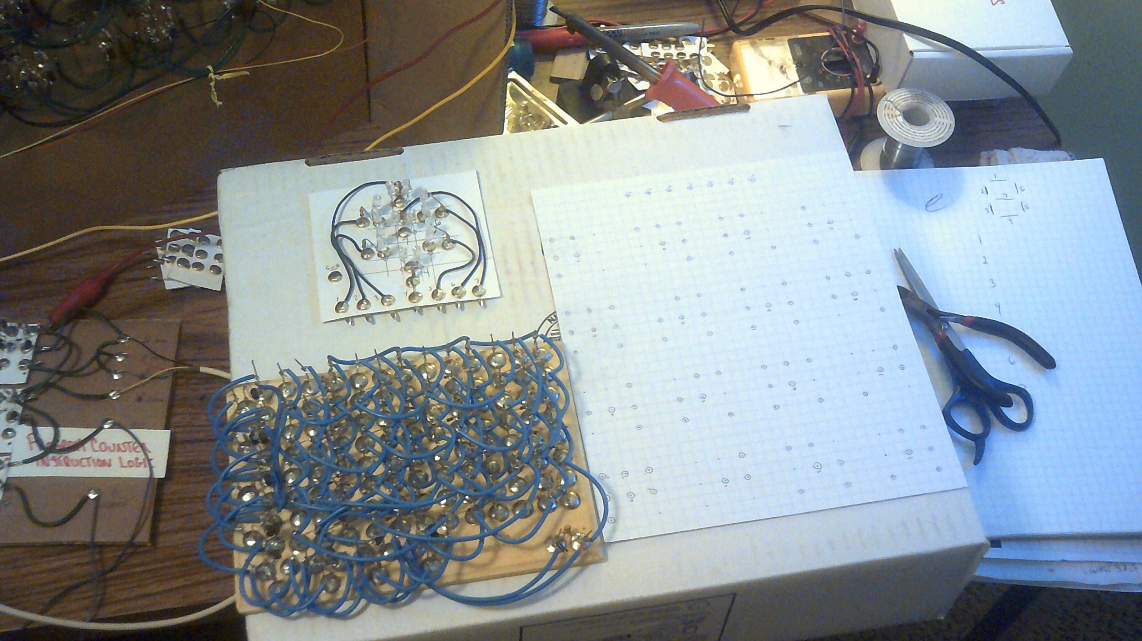
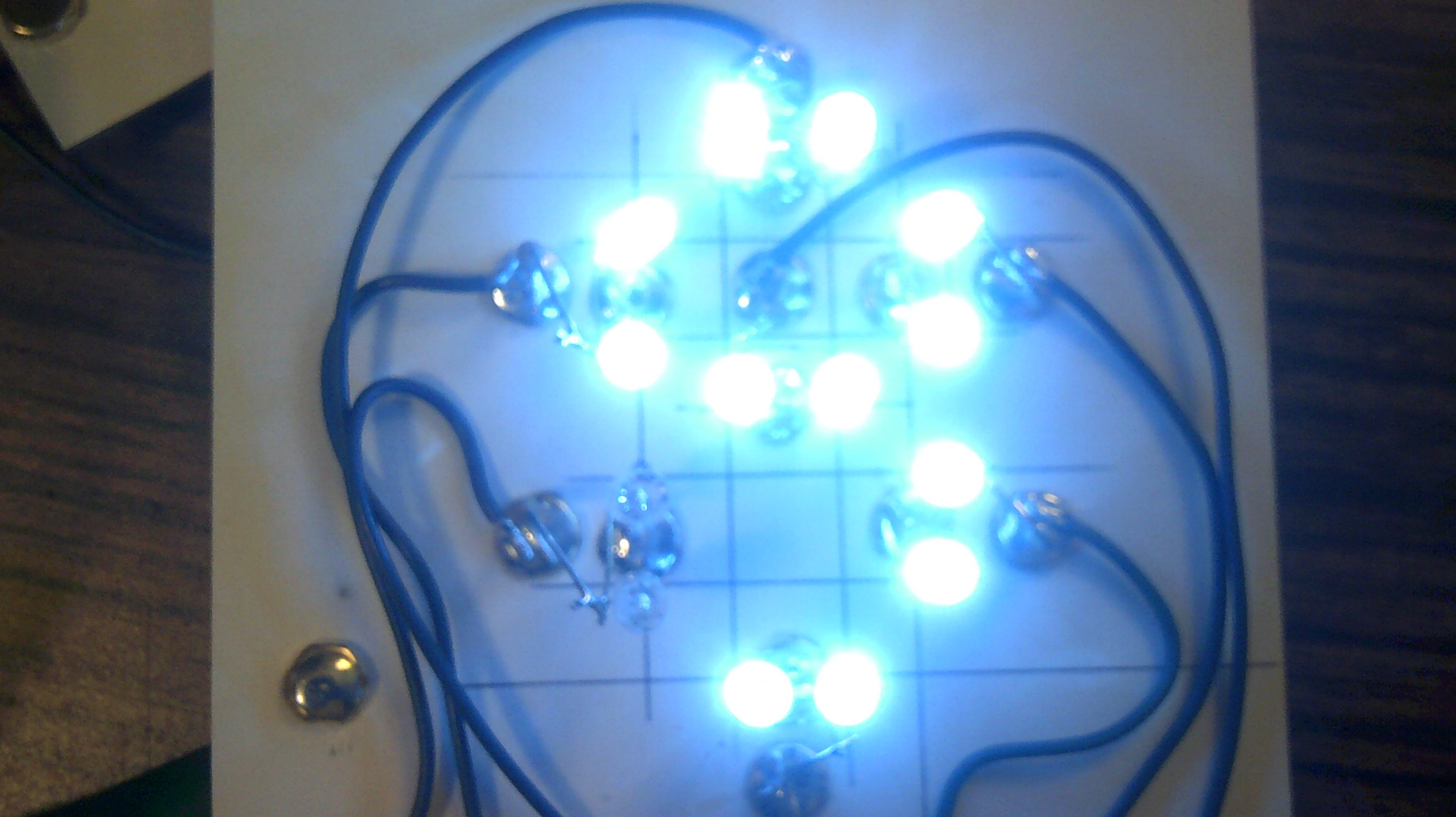
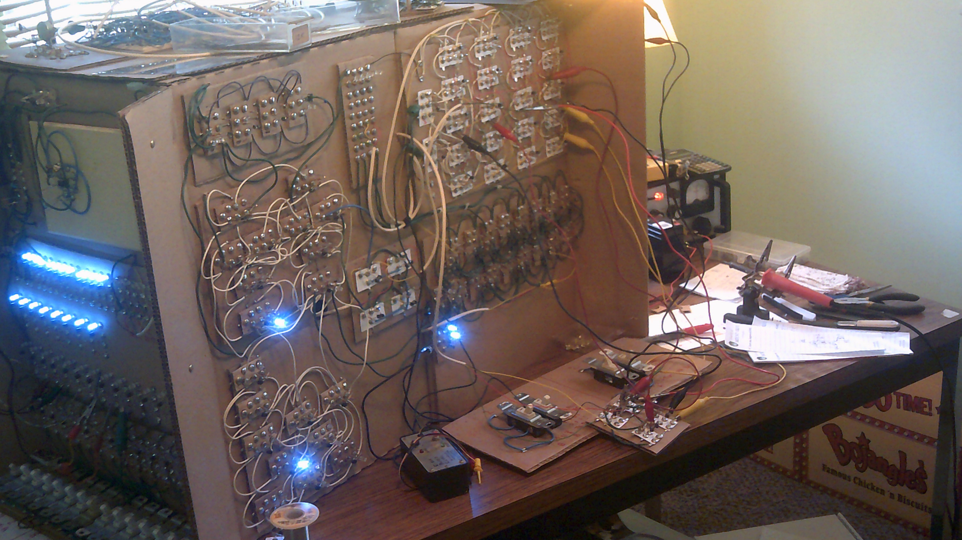
October 9, 2017 - The first Brainwarp read board with the logic gate modules glued down. Now to wire them up :-)
![]()
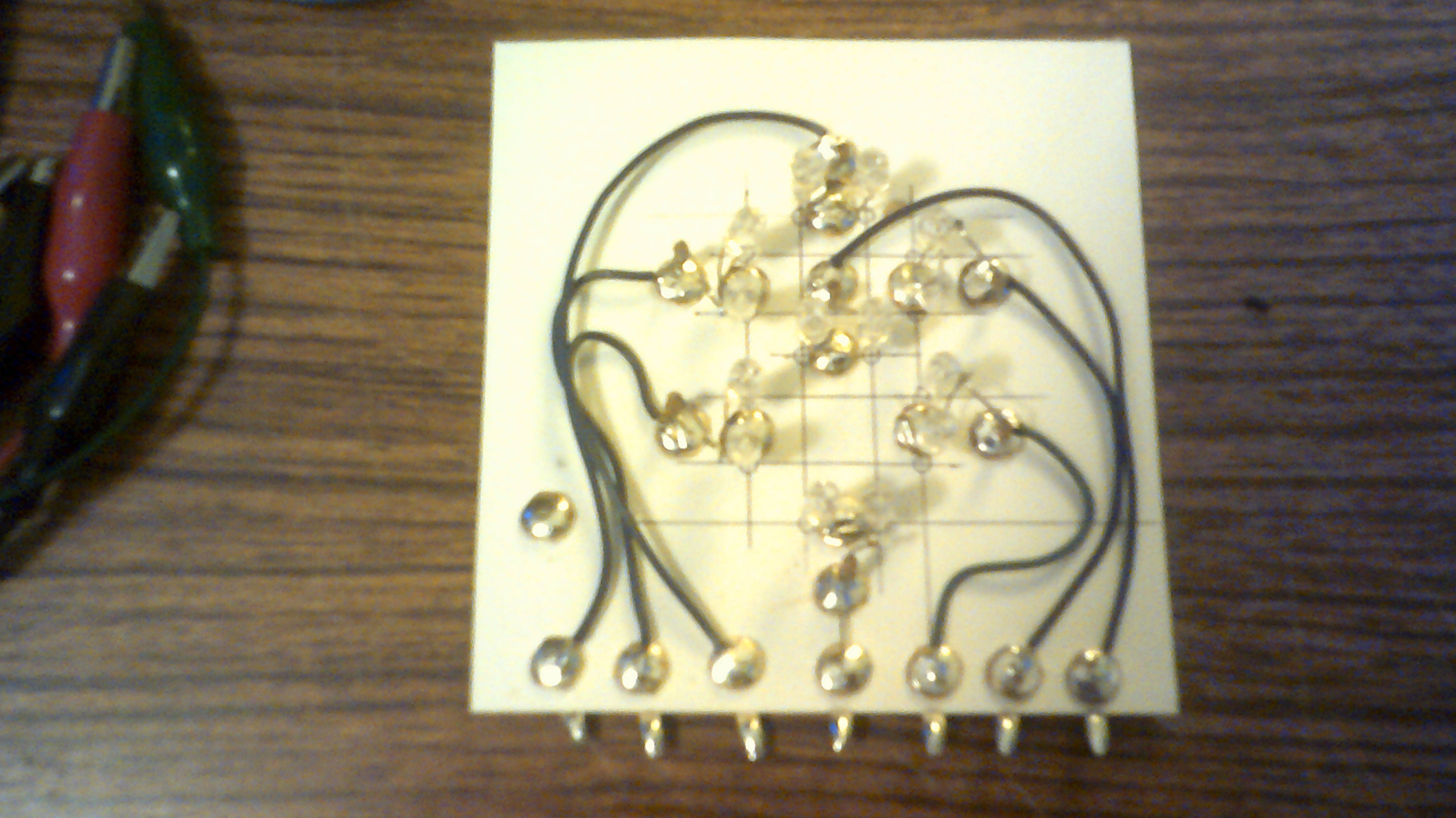
This is the wiring needed to read just one instruction on the panel.
![]()
-
September 26, 2017 - Hackaday Prize video added
09/27/2017 at 10:45 • 0 commentsI have added the Hackaday Prize 2017 video so just scroll up to watch it if you don't mind a 9 minute video :-)
-
September 19, 2017 - New display panel for 7 segment display
09/19/2017 at 11:26 • 0 commentsAnother cardboard box will be used to mount all the logic needed for IO's 7 segment display. This will include the 4 to 16 line decoder, character matrix diodes and the led display.
![]()
As of September 24 this is the display up and running
-
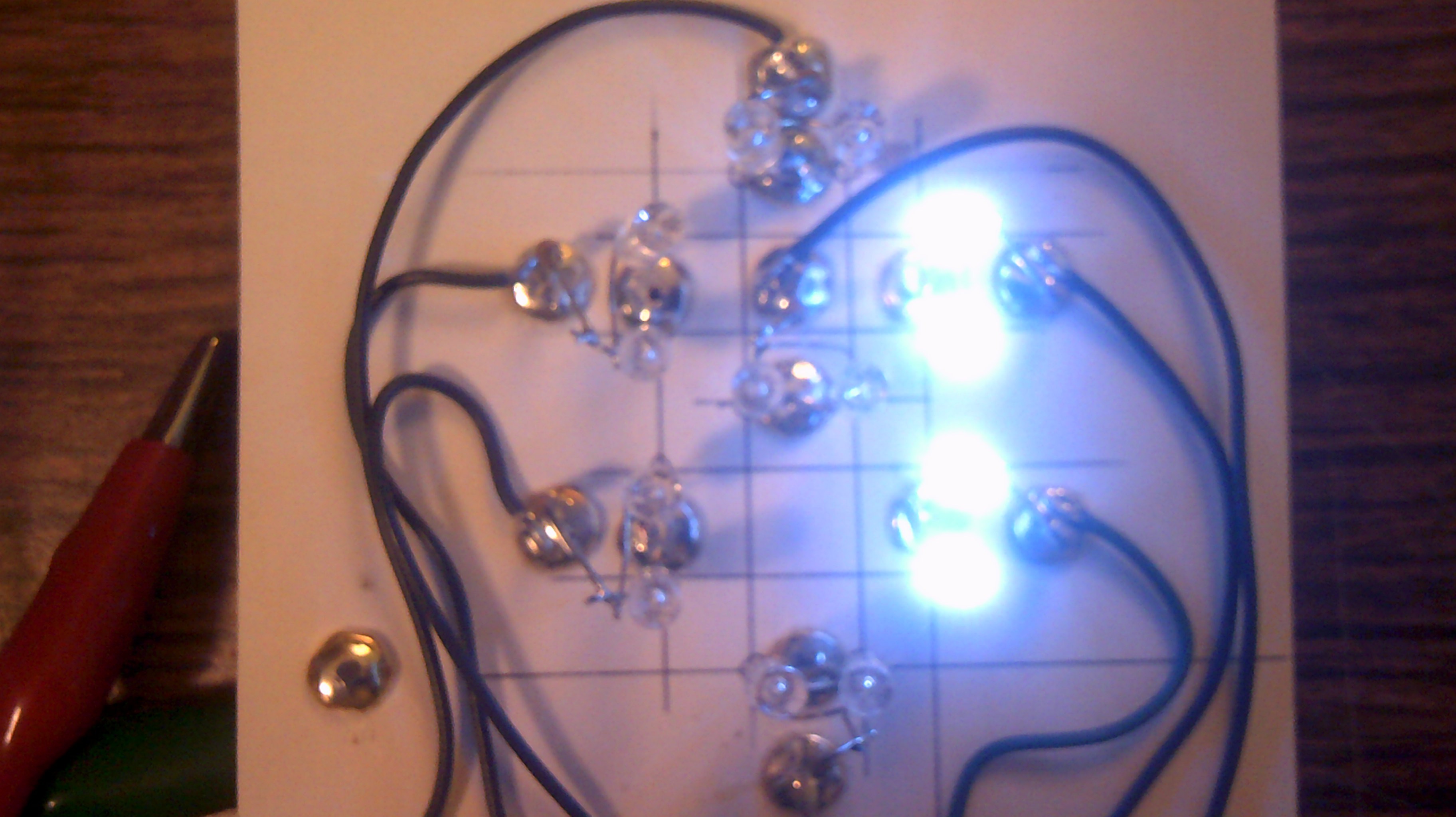
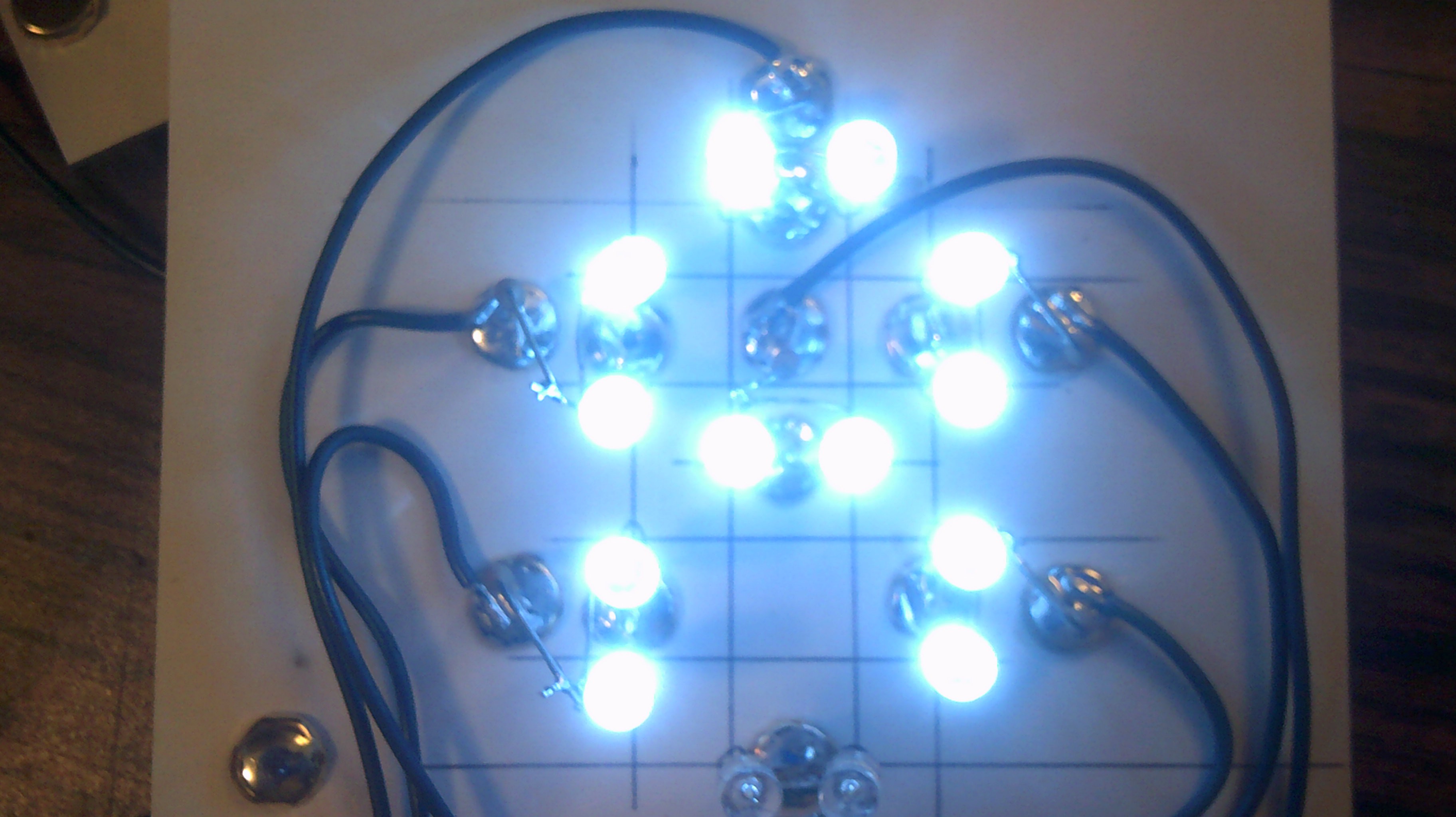
September 19, 2017 - A crude 7 segment display
09/18/2017 at 23:50 • 3 commentsWell, I got sidetracked today. I read a post about 7 segment displays and decided to try something out for IO. Please don't laugh but I think that this will fit right in for IO's front panel.
Here is the unpowered 7 segment display using my Christmas leds.
![]()
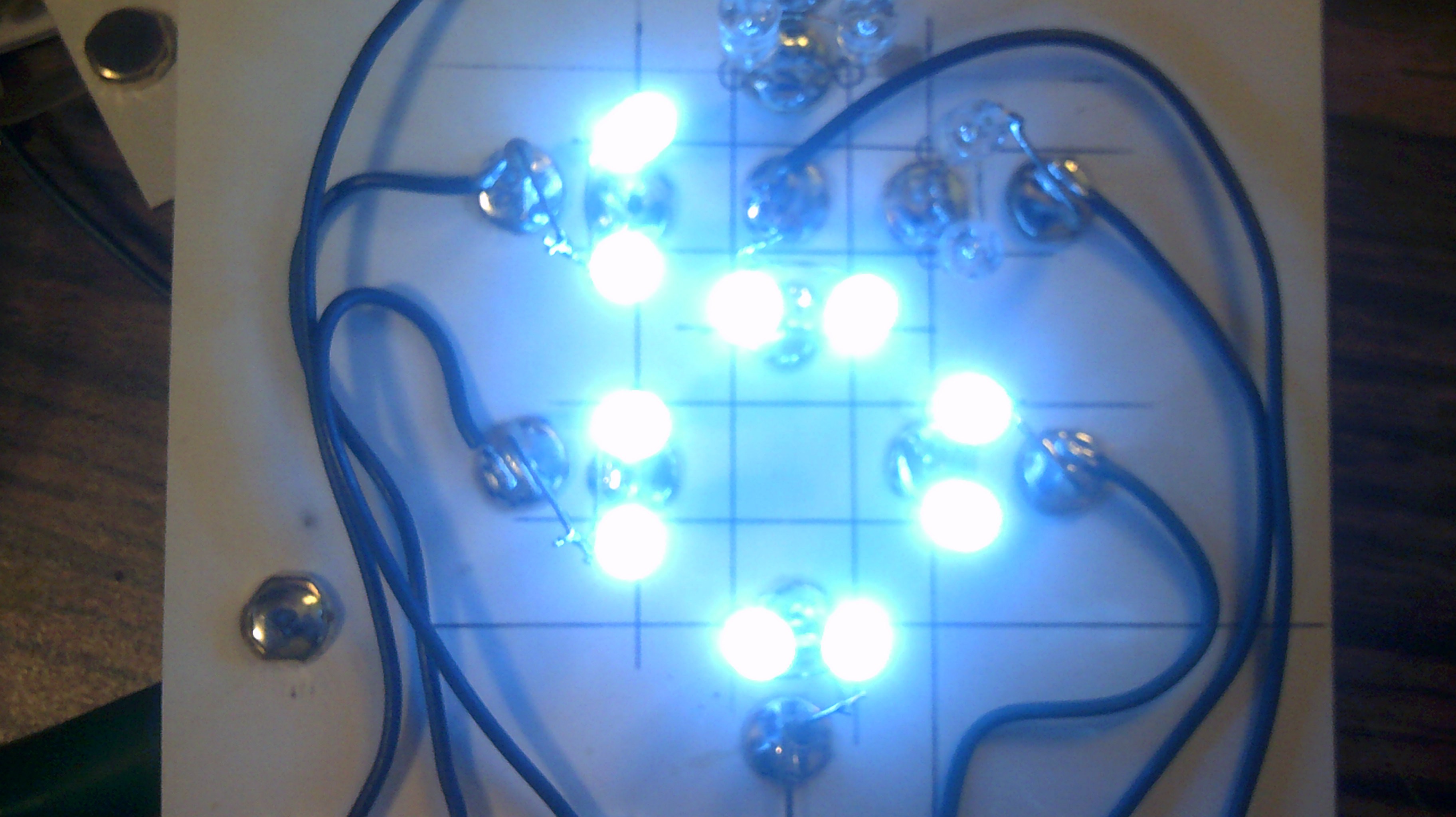
Number 0
![]()
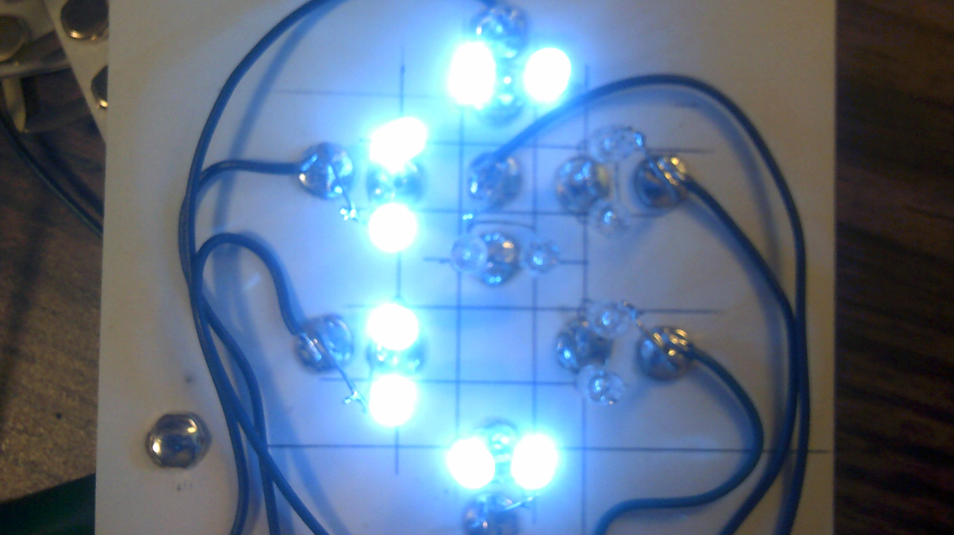
Number 1
![]()
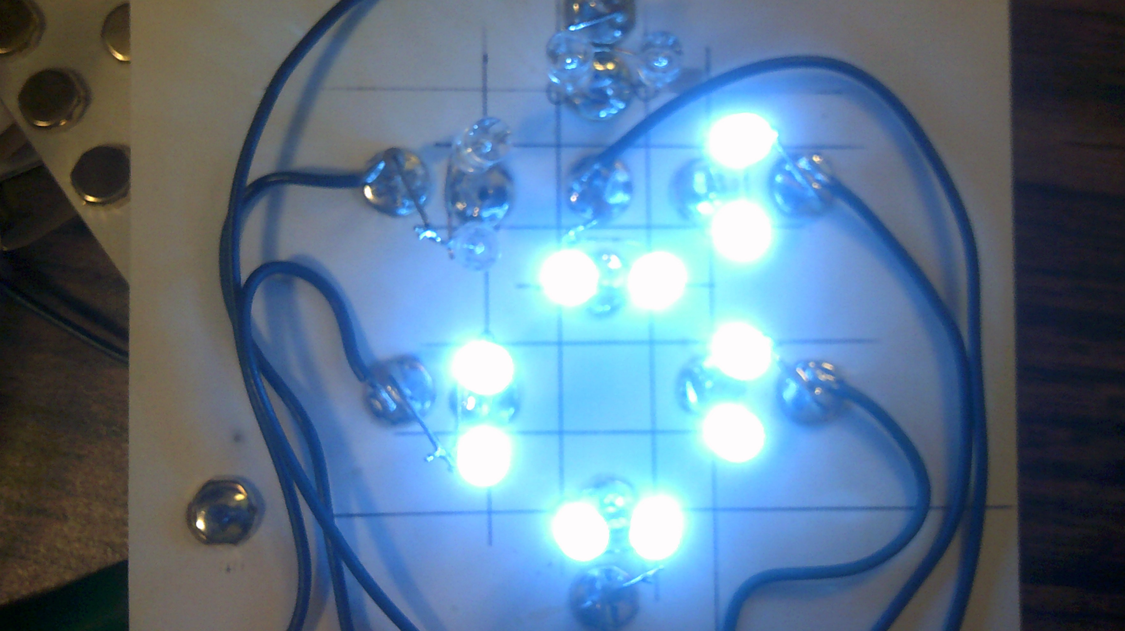
Number 2
![]()
Number 3
![]()
Number 4
![]()
Number 5
![]()
Number 6
![]()
Number 7
![]()
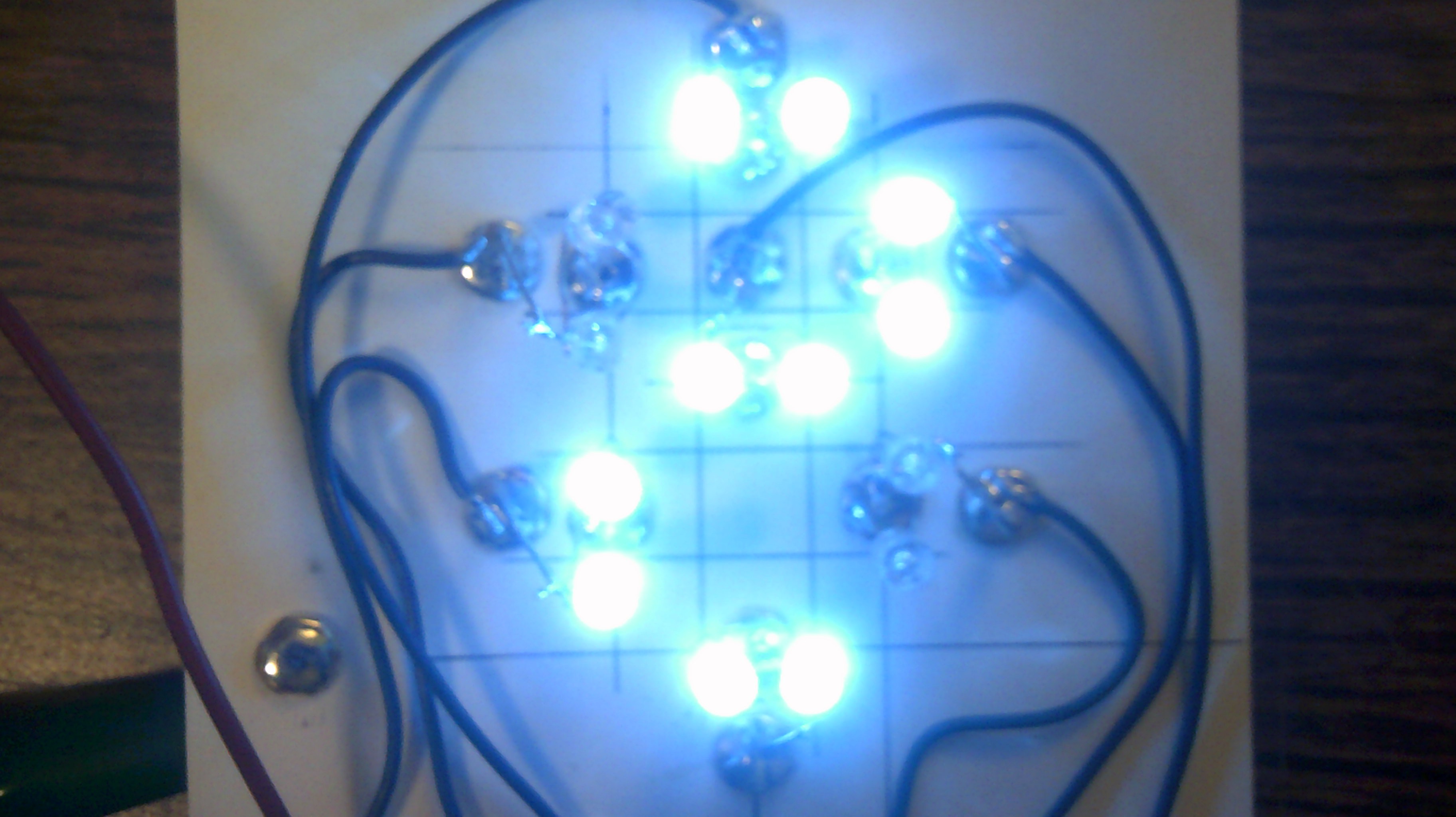
Number 8
![]()
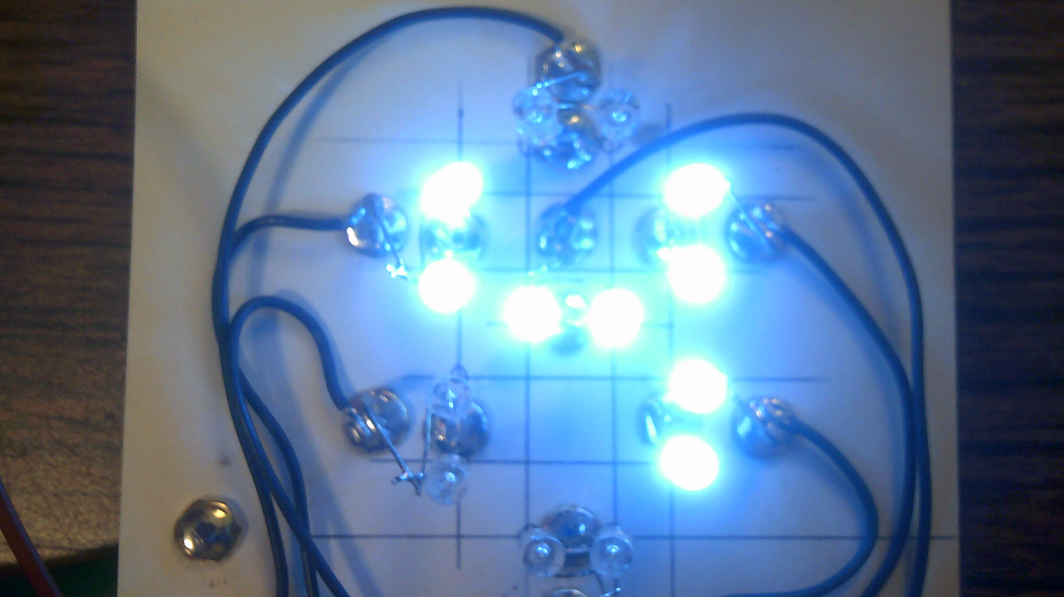
Number 9
![]()
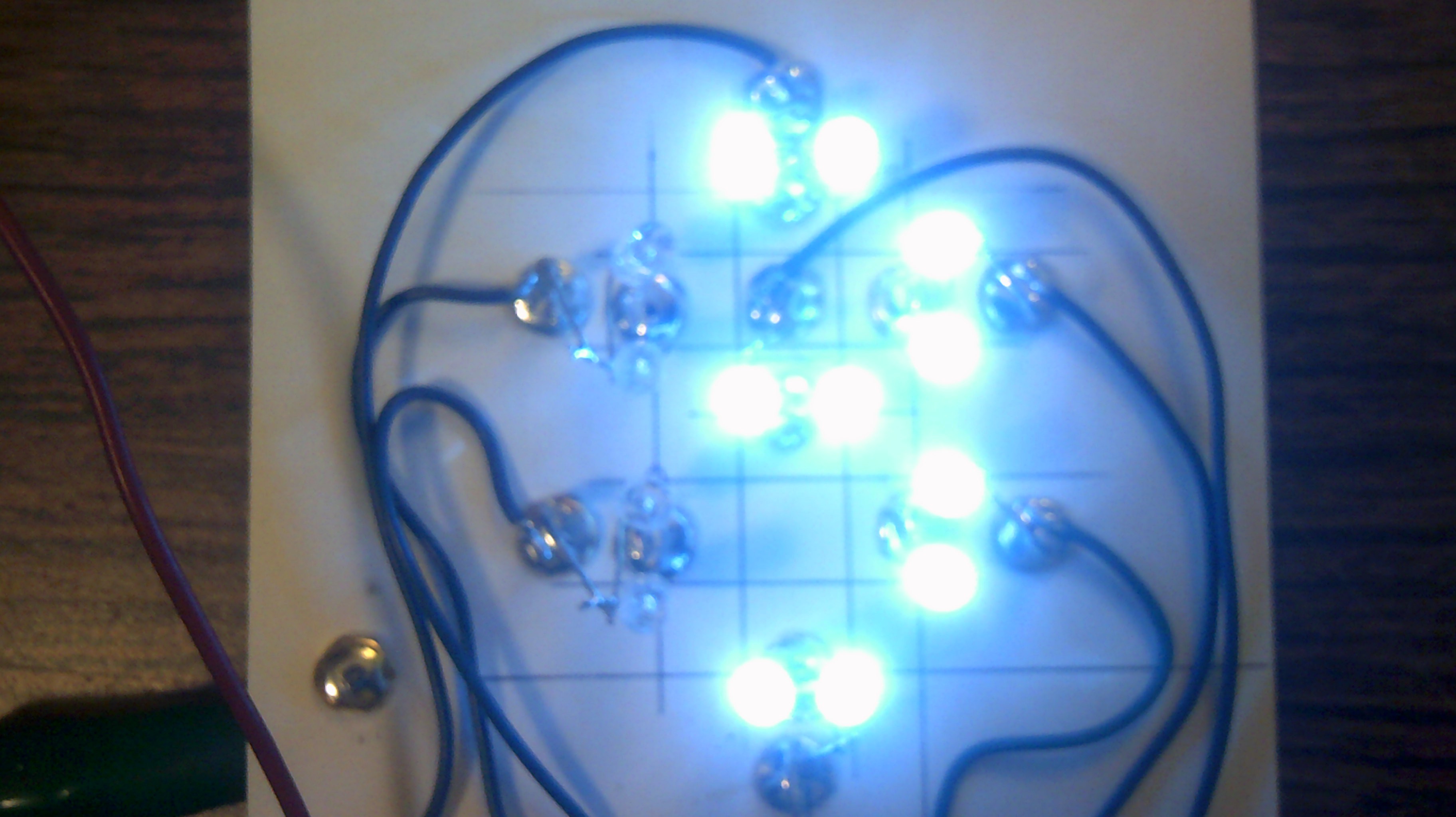
Hex A
![]()
Hex b
![]()
Hex C
![]()
Hex d
![]()
Hex E
![]()
Hex F
![]()
-
September 12, 2017 - IO's first bug ?
09/12/2017 at 11:04 • 4 commentsWell, IO is back to playing mind games or else it has its first hardware computer bug. I am seeing a garbage bit getting into the system and even with a slow clock speed, I can not keep track on where it is being introduced. Guess it is time to add a single step function to the front panel. I had planned on adding it later but now I really could use it :-) With all the Leds I should be able to figure this out...
Ok now, it is September 16, 2017 and I think that I have squashed IO's first real bug. Found that in some buffers leading to the Accumulator there were 120k resistors that should have been 12k in the transistor collector path, Opps my bad :-) I have been running IO with the 12k's for several hours without any problems. Folks out there need to be reminded that this is all new to me and now that goes for debugging :-)
September 17 and it has been 48 hours with IO running the accumulator and PC without any glitches, not one :-) Now I feel better about wiring up more circuits and working on the Brainwarp instruction set :-)
-
September 3, 2017 - A slight glitch
09/03/2017 at 08:55 • 4 commentsUpdate September 5, 2017 - IO is adding correctly once again. Could not isolate the problem so just started adding 104 caps to parts of the registers that had not already been filtered. Still have a very slight glitch with one led on the accumulator but it does not seem to
affect the system :-)_______________________________________________________________________________________________________
After running IO for several days it has developed a glitch. From start up the registers count from 0 to 15 just fine. However, after that, bit 3 or binary 4 becomes random and causes the whole thing to spit out all kinds of trash. I think the problem is in the PC but need to trace the signals from start to finish. Oh well, this is what it's ( learning ) all about :-)
-
August 30, 2017 - My short To Do list for IO
08/31/2017 at 00:13 • 0 commentsI now have a short list of To Do's for IO
One instruction register.
One cell pointer register
Five 4-bit memory nibbles for the pointer ( Just choose 5 to start with )
Brainwarp instruction card read logic
Transistor clock circuit ( this is the oldest To Do )
Add two more rows to the Dmux circuit
Logic for eight Brainwarp instructions
I have the logic circuits down on paper for all but the actual instructions. Those will be the tough nuts to crack :-) But hay, this is what it's all about, learn by building. I can read all the web pages out there but the real learning is in the doing :-)
-
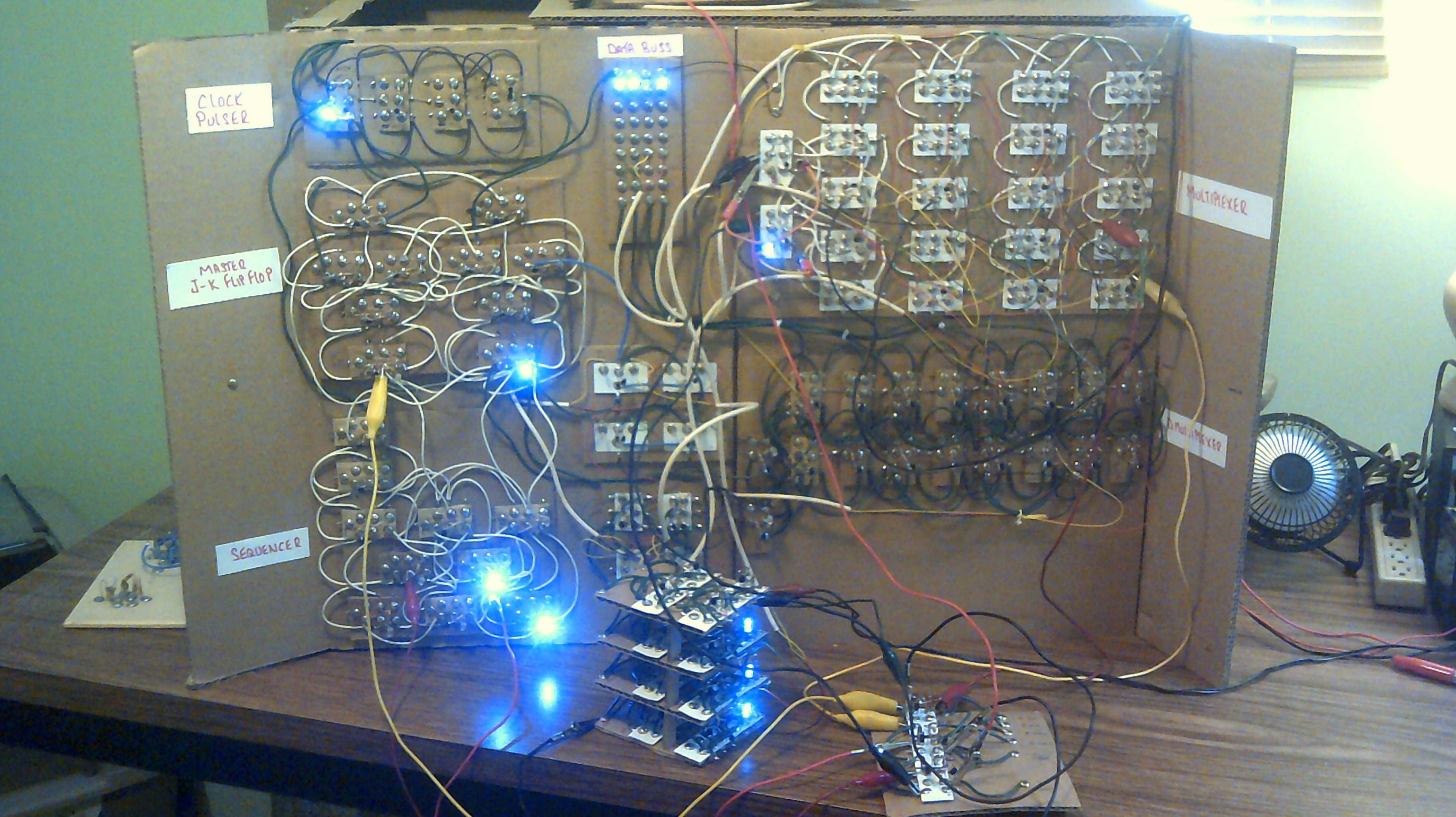
August 28, 2017 - IO is finally talking to itself
08/28/2017 at 10:44 • 3 commentsA lot has been going on these past days. Check out the video at the top of the Details section. I have been able to tie in all of IO's current sections. The Sequencer, ALU, Accumulator, Program Counter, Mux, Dmux and Data Buss are all communicating with each other. Just taking the baby step of getting the PC to increment has been a huge learning event. The first PC circuit was just a set of flip flops that fed into each other. Now I have learned how to let IO calculate and update the PC. There is a lot of work to be done but I am learning to develop an idea on how to hard wire the Brainwarp instruction set.
![]()
-
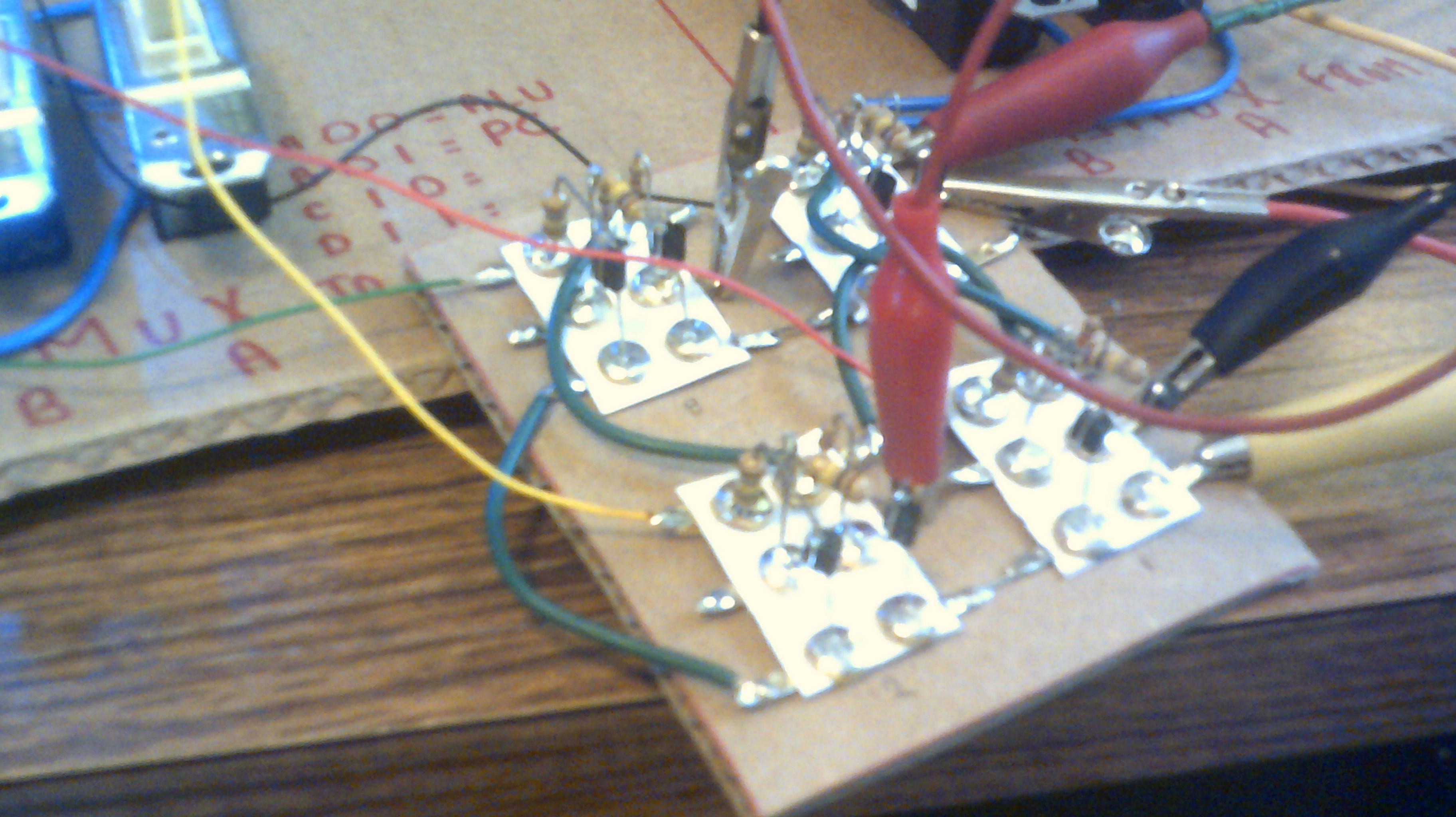
August 21, 2017 - PC signal level issues fixed
08/21/2017 at 21:02 • 1 commentI have been trying to correct the signals out from the older PC register and just finished wiring up four non inverting buffers. The outputs from the PC were 4.5 volts for high and about 0.5 for the low. My standard Nands require an input low of ground so had to correct for this condition. The following pic shows the clipped up mess but things are once again at peace with IO. Till the next issue Lol
![]()
![]()
The Cardboard Computer - IO is my name
My goal is a 4-bit CPU using recycled cardboard substrate and Diode Transistor Logic. This is an educational platform for me.

 This is the 5 input And gate using a Nand and Not gate. Led is the output side.