CriptasticHacker
-
In-Person Demo
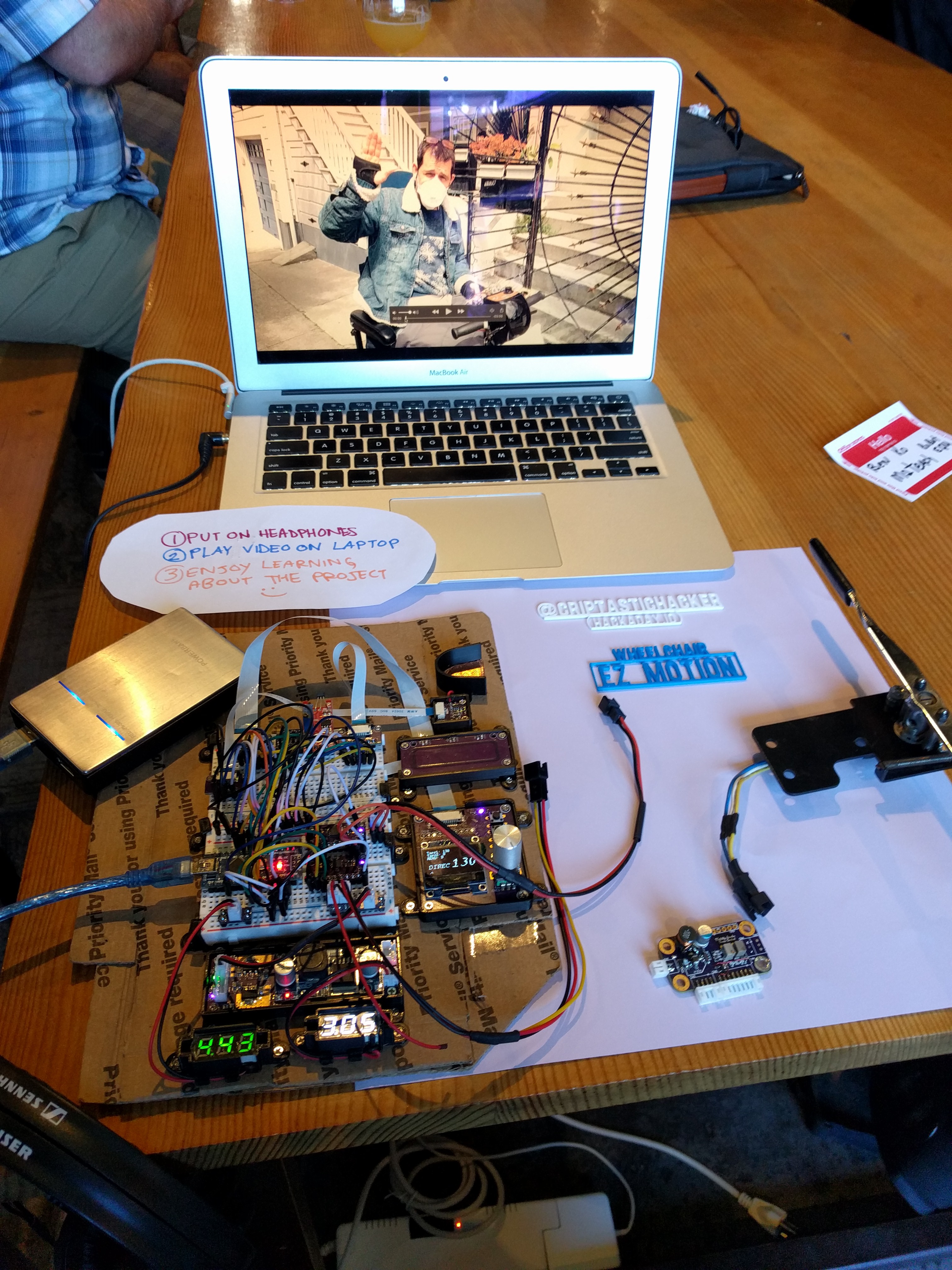
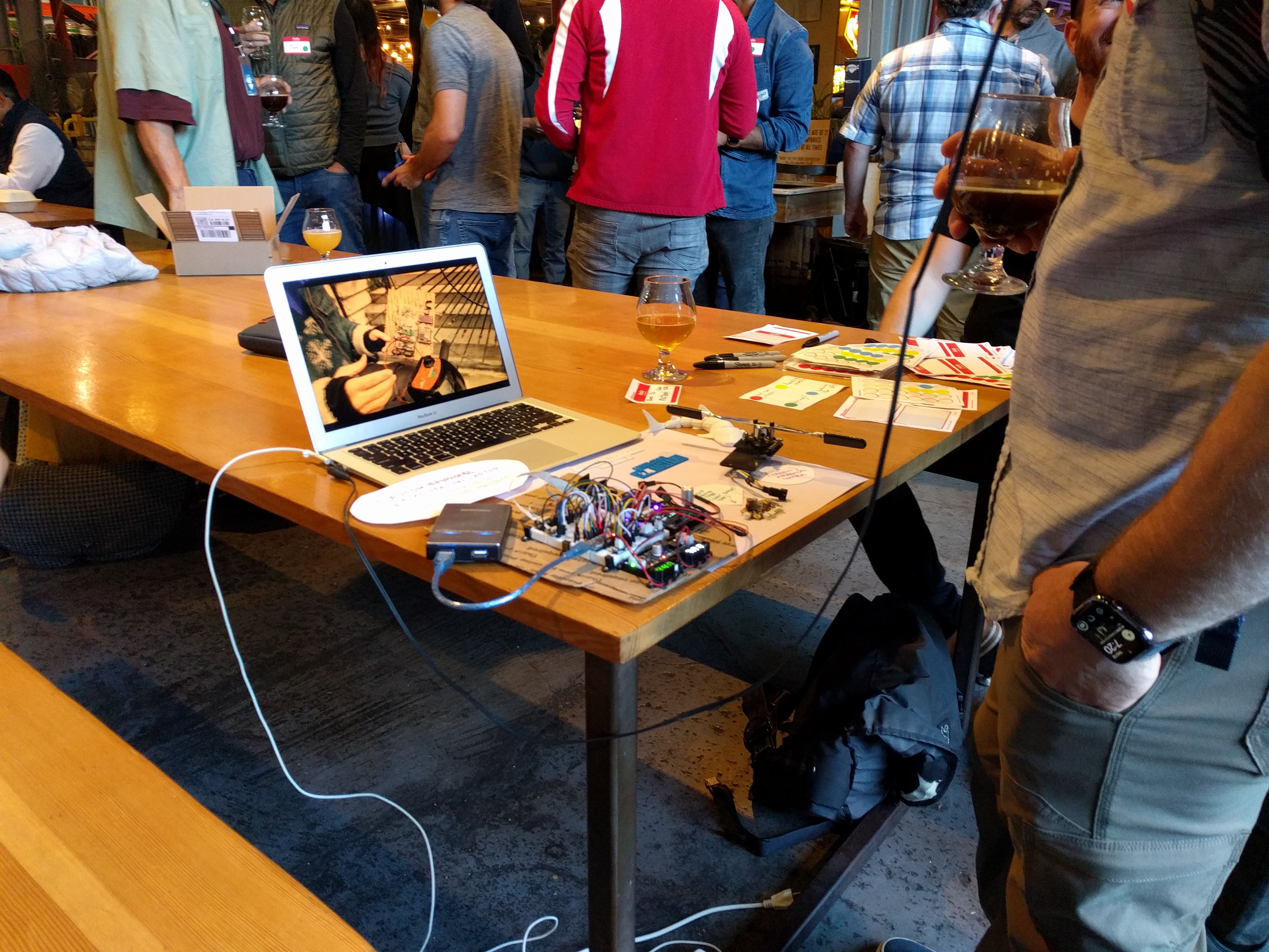
07/18/2023 at 08:18 • 0 commentsmy local hardware group had an in-person meetup, so I brought along the proto for a little demo!
![]()
![]()
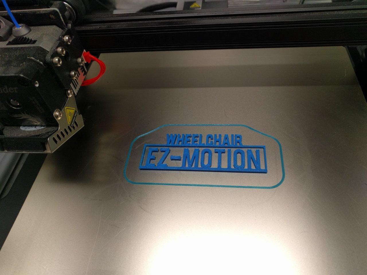
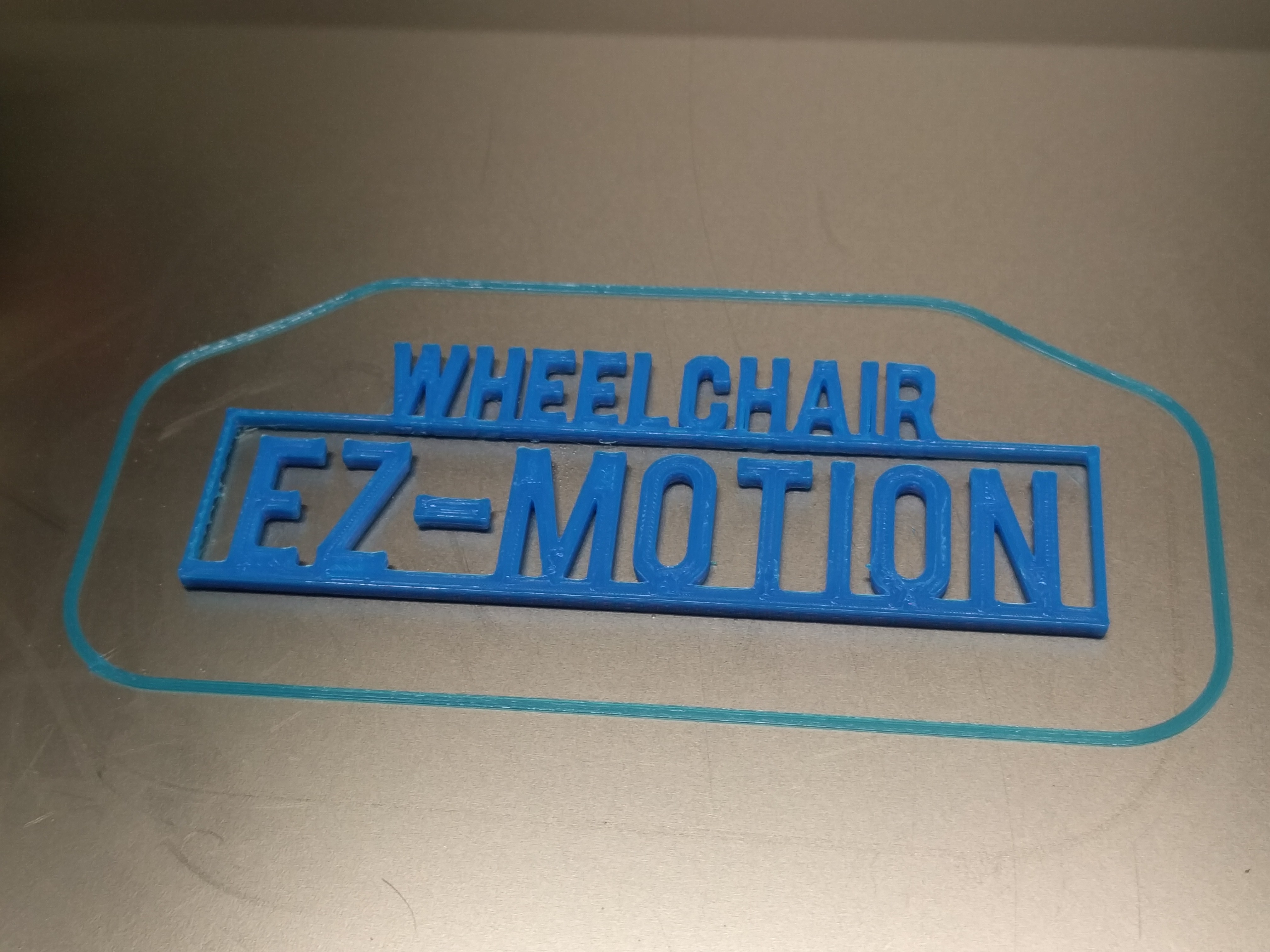
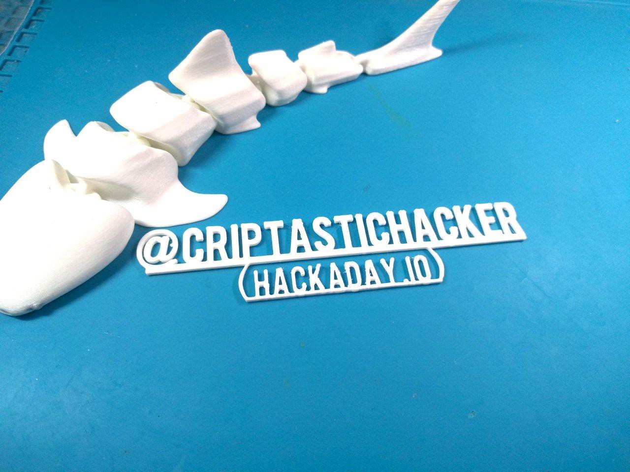
I stopped taking photos as the crowd got bigger...probably the opposite of what I should have done (but who wants to be *that* guy?) Anyway, it was a hit to say the least, with lots of people chatting about it and then being inspired to share their cool projects too :)I also had some fun 3D printing custom text for the demo. I dont know why, but this is always very satisfying:
![]()
![]()
![]()
[To be continued...]
-
USB micro breakouts + Strange Parts chat!
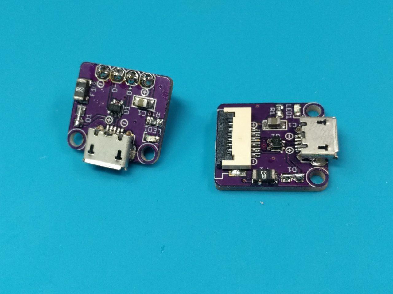
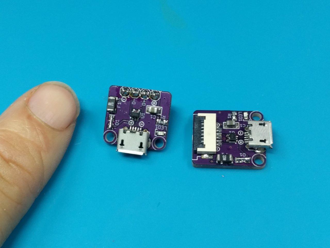
06/11/2023 at 23:48 • 0 commentsMy micro USB breakouts finally arrived and -- spoiler -- I went ahead and added a TVS diode footprint for proper ESD protection :) I went with the RClamp0503F, since it also incorporates +5V rail overvoltage conditions, in addition to the data lines. Semtech seems to have the market on USB TVS diode custom packages, which is nice. Lovely to see some smaller companies getting a piece of the pie. Semtech also has a terrific write-up on them over here.
![]()
![]()
The breakout boards came out really nice I think. Only minor quip is the SOD-123 footprint for the diode - a little small if I want the 2A supported current of USB 2.0. Shorted it here for now (it's not necessary) but I have a part in the mail to swap in later.
If the TVS chip looks small, that's because it is. SC-70s are still pretty tiny, even if they are leaded. Smaller than this is a BGA, which is more trouble than it's worth, IMO.
-- Strange Parts Interview --
![]()
![]()
I had the chance to chat with my good friend Scotty (a.k.a "Scotty the iPhone Guy" ) from Strange Parts this past week! He was nice enough to let me plug this project. A fun off-the-cuff chat about hackerspaces, right to repair, wheelchair hacking, and more:
https://www.twitch.tv/videos/1836877614 [EDIT: offline for now, womp]
-
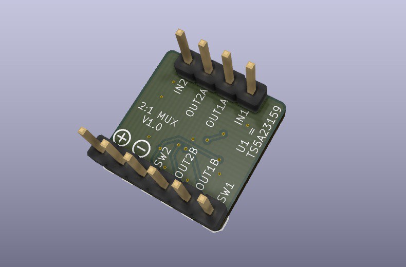
2:1 MUX assembly
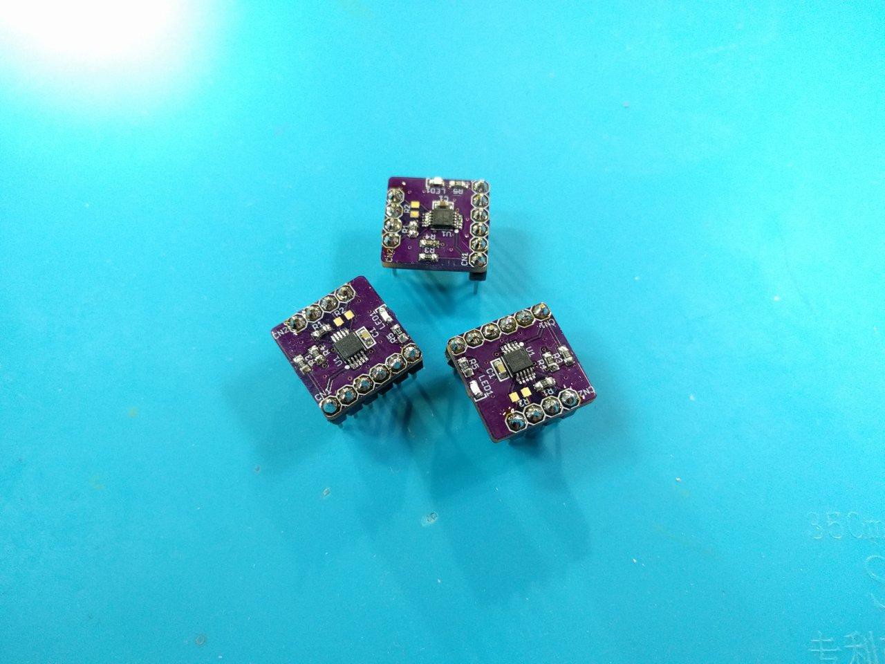
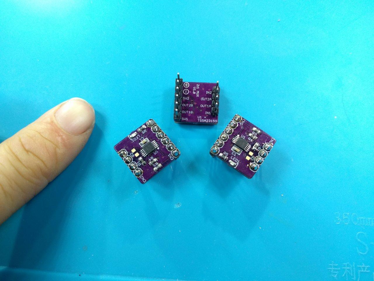
06/01/2023 at 18:58 • 0 commentsMy 2:1 analog MUX PCBs arrived, and got them all assembled :) Read the logs below for more details - I'm using these to make the digital pots more precise, and give me full speed :)
![]()
I'm a fan of TSSOPs...pretty easy to solder, and even easier to fix mistakes or shorts. 0.65mm pitch is small, but still doable. These boards came out pretty nice...but how small are they really?
![]()
Here is my finger for reference...pretty small still! Not worried about fitting everything inside the wheelchair tiller :P
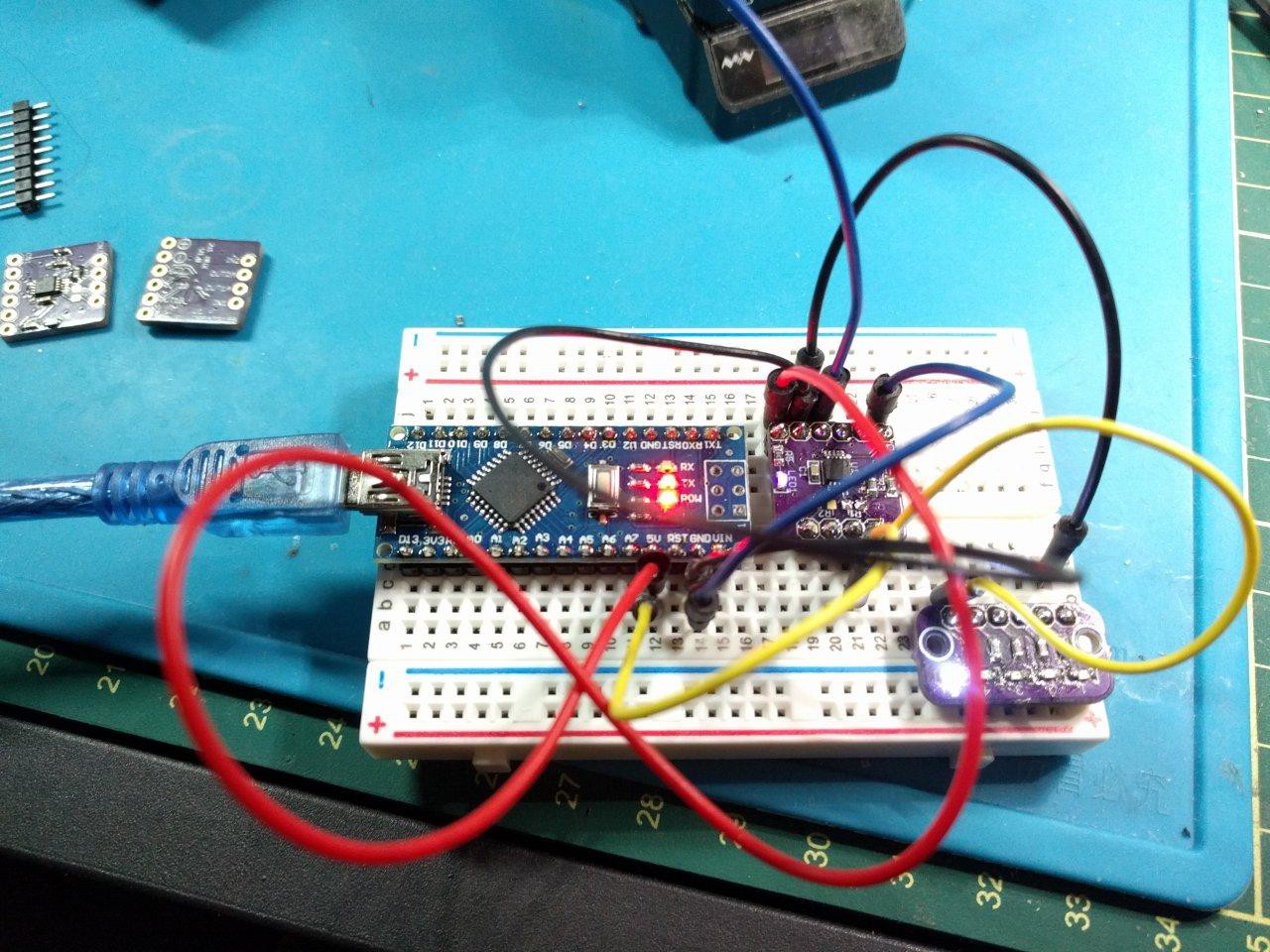
Now, to test the functionality with a simple LED on/off. I cleaned up the Arduino built-in debounce code (it's a bit iffy, but works) and made a toggle function:
![]()
Success! The MUXs work exactly as intended on first iteration design :)
[to be continued...] -
Ah, Break Out! (le freak, c'est chic)
05/24/2023 at 02:21 • 0 commentsBreakout PCBs have been a major theme in this project. It has really upped my game to have more modules and conversion PCBs - many of which I didn't realize I needed in my toolkit. Honestly, I'm surprised more of these aren't already available. But *shrug* gotta make it happen either way!
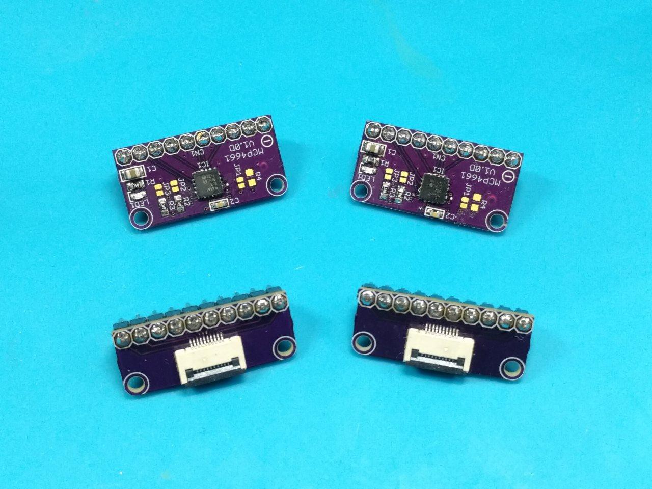
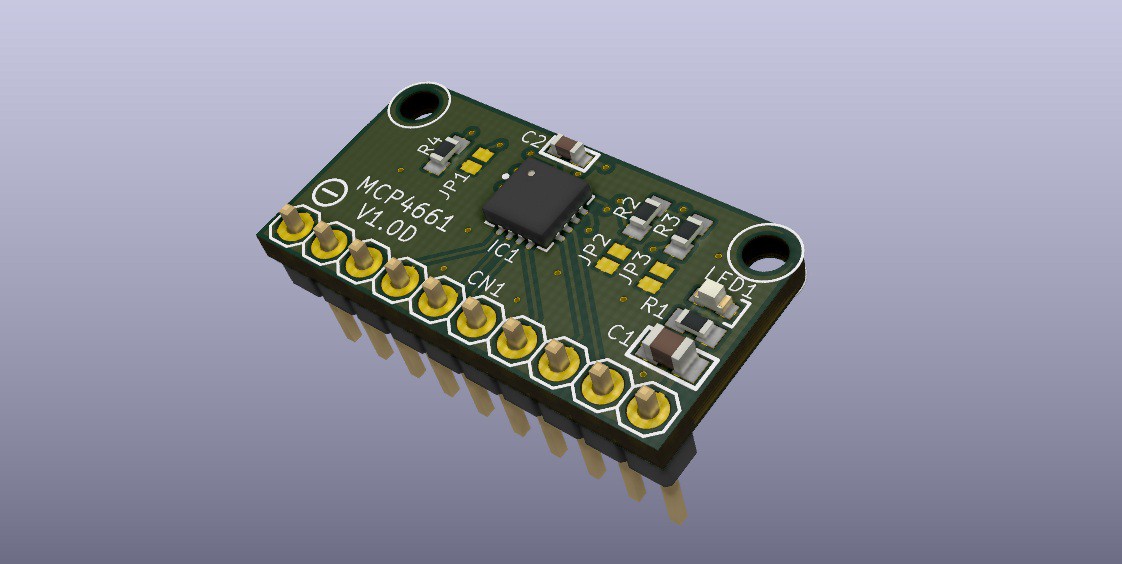
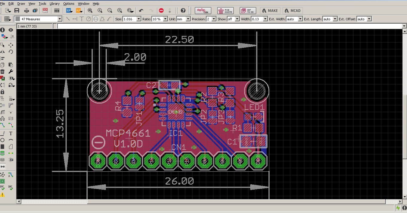
The MCP4661 digipot breakouts came out beautifully - and they work 100% perfect too, address changes and all :)![]()
I made about a dozen different FPC -> 2.54mm designs so I'll have lots of flexibility prototyping. Forgot to put the version silk on top (it's underneath) but these are otherwise quite ideal. I used a new trick to help with soldering high-pitch pins and the MHP30 mini hotplate really does wonders for assembly on these.
Here's one with my finger for scale:
![]()
Sure beats the ugly ol' breakouts I've been using up to now!
![]()
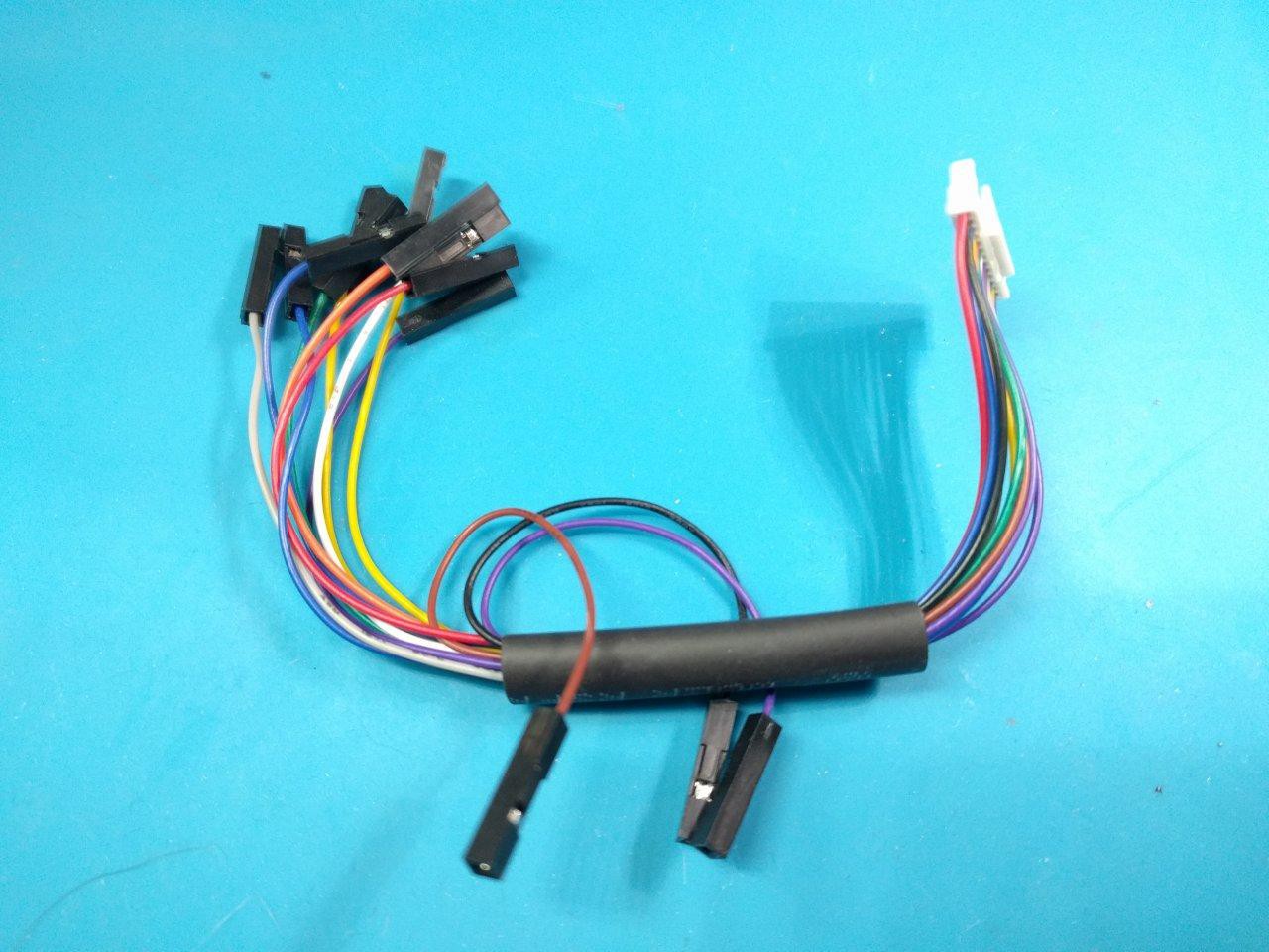
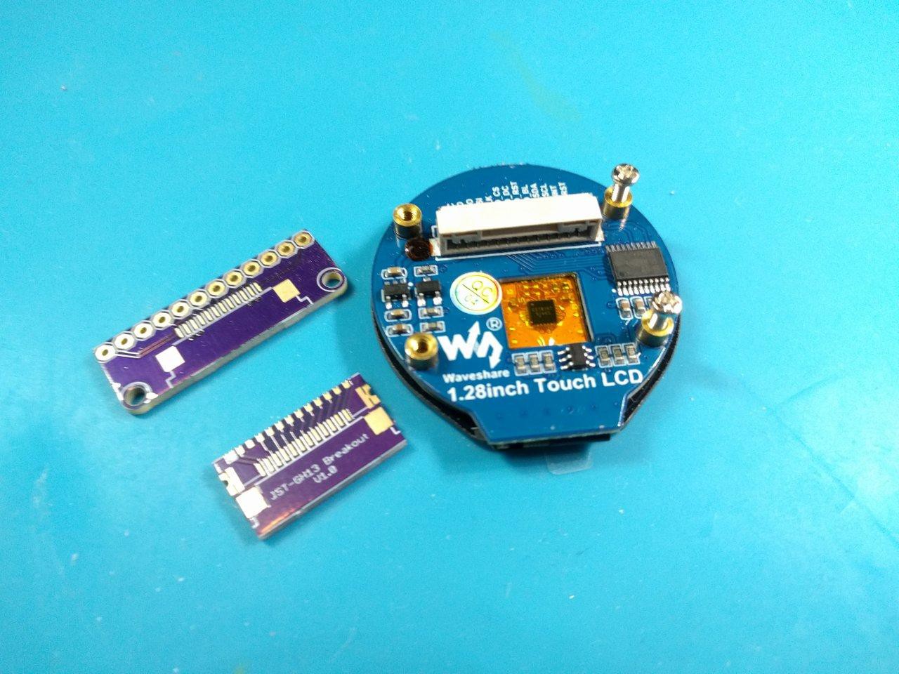
Additionally I've been excited about using some fancy round LCD gauges for this project. The GC9A01 by WaveShare is an ideal candidate here, but the only touch screen variant (also 5V level shifter) I could find has a frustratingly crappy cable harness with a very uncommon JST-GH13 connector (1.25mm pitch)....
![]()
Notice the female breadboard contacts (!?) all split and bent into tangly curves. Ew, no thanks!
Time to breakout! (le freak, c'est chic-- yes, the inside of my head is an interesting place :P)
![]()
![]()
![]()
![]()
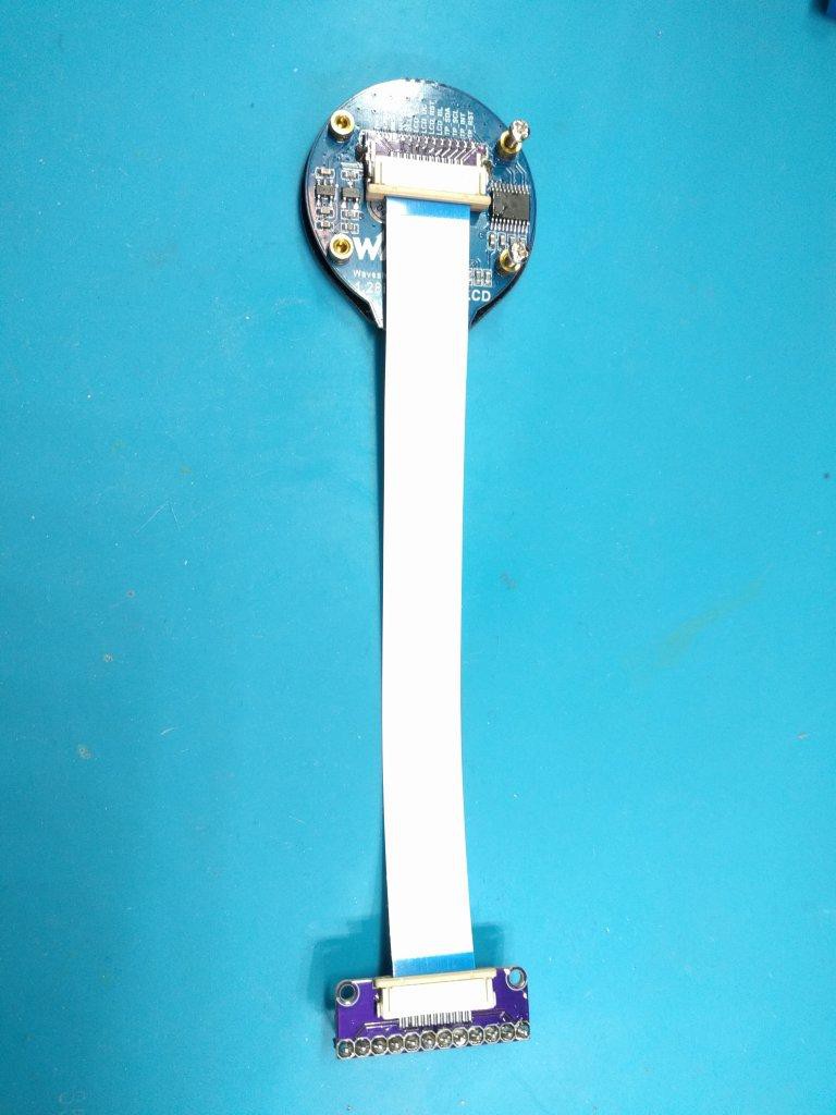
Ah, much better! Now we have a nice pluggable FPC-12 1.0mm to work with ^_^
note, I can get away with using a 12-pin connector since MISO is unused (output from the display to the controller).
[to be continued...]
-
You Ess Bee
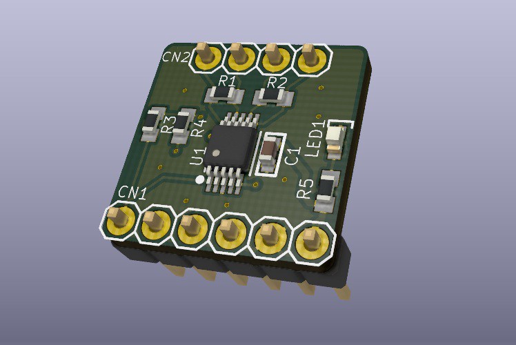
05/20/2023 at 06:36 • 0 comments![]()
![]()
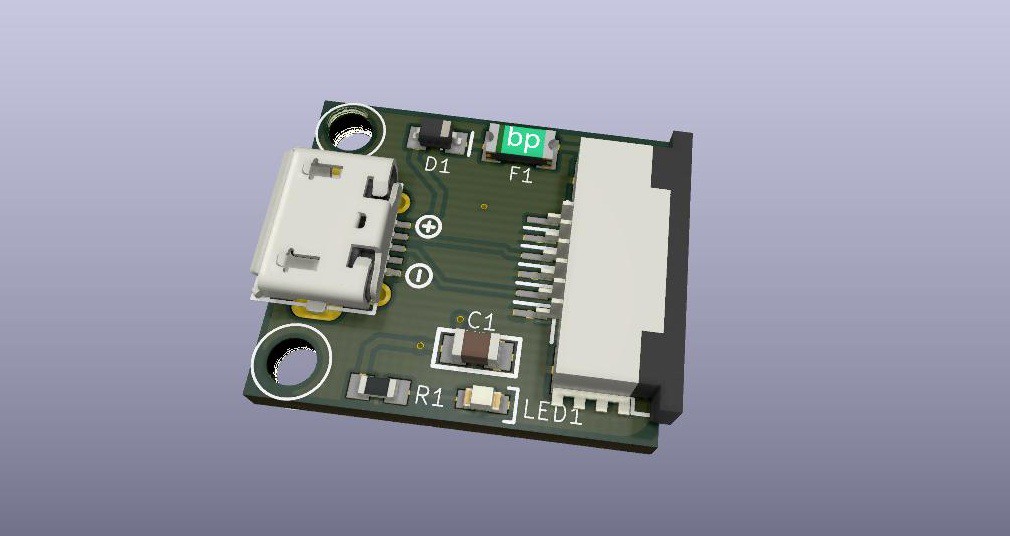
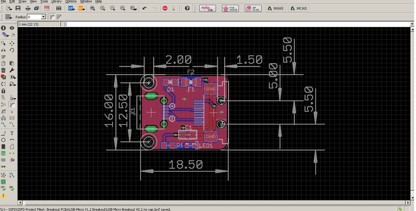
I designed a simple USB micro breakout PCB for my programming needs. Suffice to say this project is going to need a lot of firmware updates, and I'd like to do that on my laptop "out in the field". Since the project is meant to be installed into the tiller assembly, I'll need a way to reprogram / update firmware without tearing it apart each time.
There's nothing too fancy here, just a diode to prevent power feedback, a PTC fuse, power LED, and decoupling cap. I probably should have included a spot for TVS diodes (transient voltage suppressors which absorb voltage spikes) but I've honestly never had a project that needed them and I can also add em to the main MCU PCB down the road or update this one later on. Optimizing this project for speed at the moment!
I did get creative with one thing here though - 2x secret cutouts under the FPC connector. I can model the mount this board goes in to take advantage of those holes for some sneaky structural support while keeping it still at only 2x screw mounts :)
This micro PCB will eventually be enclosed in a custom panel mount 3D printed enclosure. Ive designed these before, and they come out very nice. It's always a shame to me that more panel mount parts aren't produced these days, as so much has been streamlined for a waste economy of large scale manufacturing. Anyone remember all the cool panel mount jacks they used to have at Radio Shack and such?
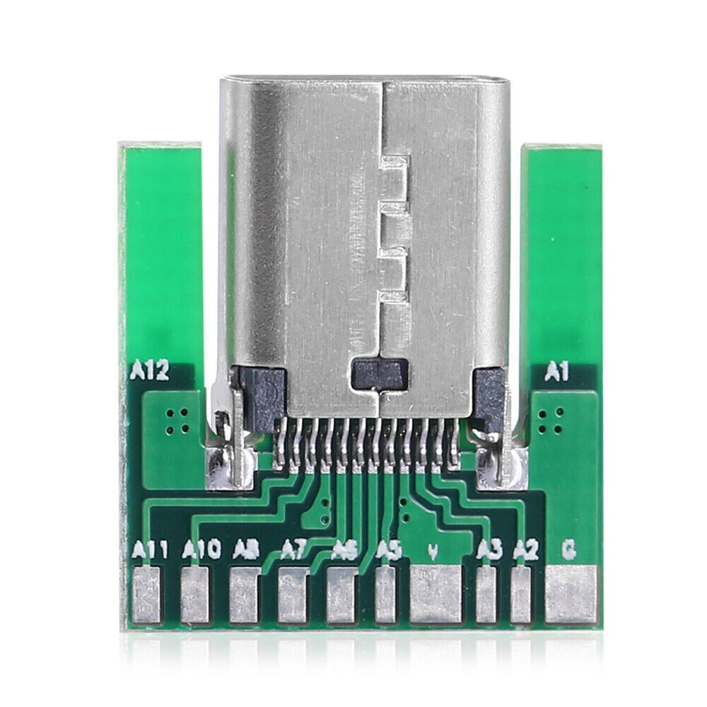
I went with micro USB since the footprint for USB-C is a frustratingly small pitch:![]()
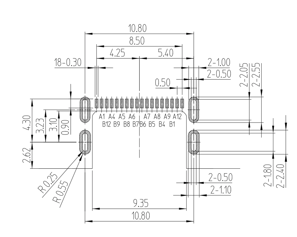
Even the breakout kit resorts to an edge mounted jack, because of how fine this footprint it. Seriously, look at the land pattern spec:
![]()
This is a standard right-angle PCB mount USB-C connector. You see that pin pitch? 0.30 milimeters! That is significantly finer than QFNs or TSSOPs (0.50mm/0.65mm). I mean c'mon, that's just cruel and unusual punishment to the hand-solderers out there!
So yeah, USB-C programming is a breakout-only affair for my home manufacturing for now. Thus, the old reliable USB Micro :)[to be continued...]
-
Full Range MUX (be gone, wiper resistance!)
05/08/2023 at 20:10 • 0 commentsOne drawback of digital potentiometers is that they have an inherent "wiper resistance" - essentially the RDS(on) of the internal FET. (RDS(on) is the drain-source resistance of all FETs). All electrical switches have this, but for some reason with (most) digital potentiometers it's fairly high. In the case of this project's MCP4661 it's a (whopping) 100 ohms. That's almost as much as a 1970's 74HC4052!
This can keep the pot from extending to "full range" - i.e. fully open or closed. Which could mean reduced reference voltage to the wheelchair's MCU....which could mean less SPEED :O I mean, who want's to go slower??Fortunately, there's a workaround. By using a modern analog MUX, I can achieve 100 times the reduction in this resistance. There are many low RDS(on) options nowadays, and I decided on the TS5A23159DGSR due to it's price, voltage (5V logic), availability (on hand, yay!) and easy-to-solder TSSOP leaded package.
![]()
![]()
The idea is simple, lets say our stock pot is labeled:
A---W---Bwhere W is the wiper and A and B are the opposite terminals
When the MCU scales the digipot to the end of B (i.e. 100 ohms from W to B, the final "shorted" value due to wiper resistance), this new MUX board will close it's switch creating a 1 ohm short across W and B terminals and add 100 ohms in-line to the A terminal :)
![]()
[to be continued...]
-
There Shall be Shunt!
05/07/2023 at 08:06 • 0 comments![]()
![]()
![]()
![]()
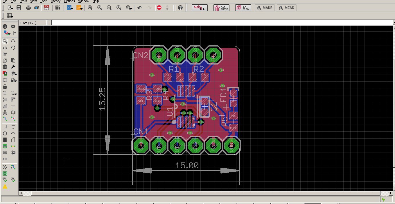
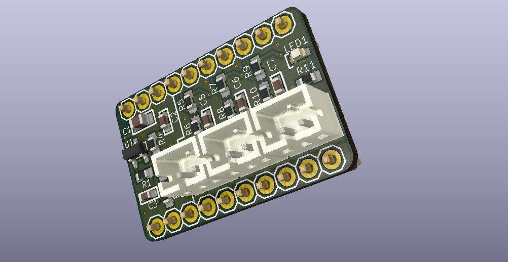
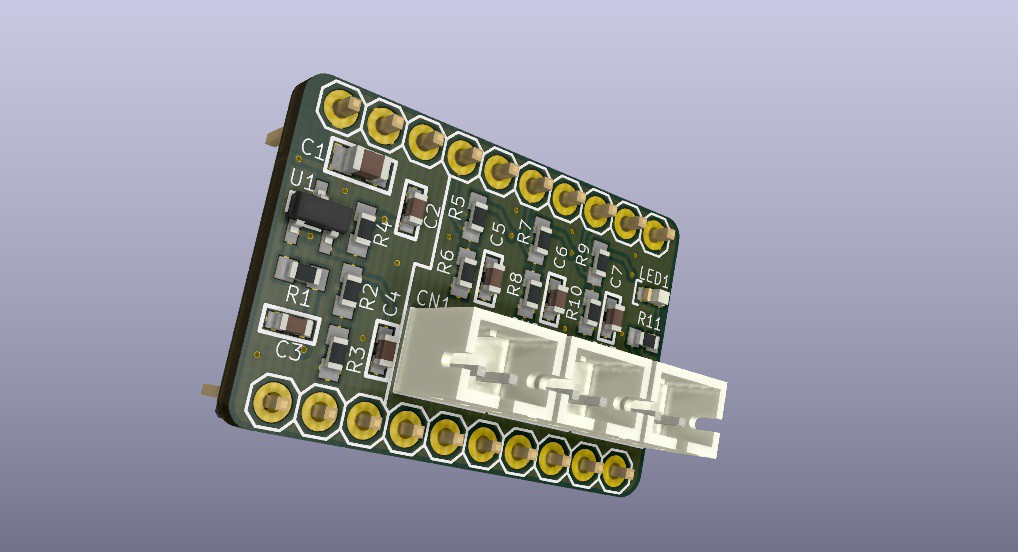
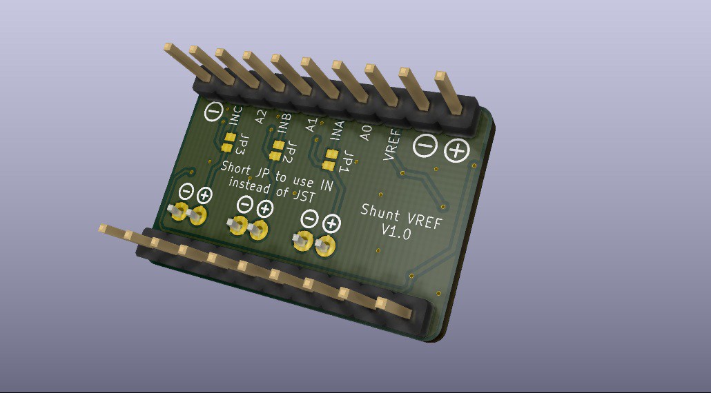
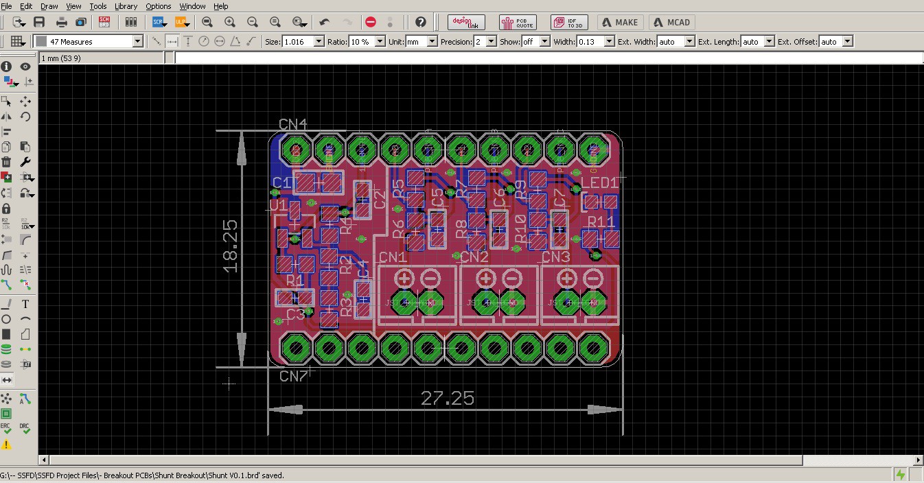
Got another PCB on the way - this time it's a prototyping shunt VREF regulator.
This nifty board will be useful for anytime I need to prototype analog voltages to accurate readouts from an MCU. It has 3x precision voltage dividers w/3x JST-PH2 connectors, and a precision TL431 shunt regulator to provide a high-accuracy reference voltage to any microcontroller. This will be useful for measuring:
- Digi Pot1 and Digi Pot 2 real time feedback (so I can put away my darn DMM lol)
- VBATT (27V+) measurement
or +5V / 3V3 measures
Looking forward to nice accurate battery measurements, although I realize it's still a step down from a current monitor. But that's a little too invasive of a hack right now (I don't want to splice MCU or motor power wires), so I think this will do nicely.
[to be continued...] -
Digipot Breakouts! (and firmware)
05/06/2023 at 06:13 • 0 comments![]()
![]()
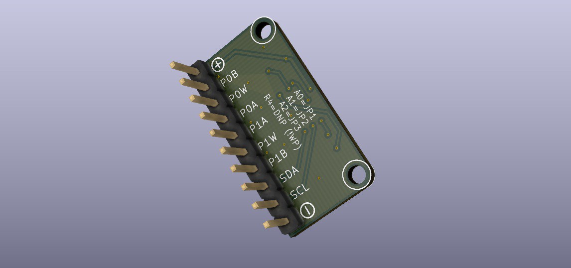
I made 4 different versions, here's a 3D model of one of them. There's QFN + TSSOP breakout versions, and then I made FPC + 2.54mm breakout versions.
![]()
![]()
--- DIGIPOT ---
These breakout PCBs have the built in jumpers for setting the I2C address - and, important note - the datasheet recommends A1, A2 be "non-static" that is, in a pulled high or low state. Power LED, decoupling caps, and a clean layout with some clear silk identifcation for pins is going to make these boards a winner. Soon to be very useful I think (when they arrive!) :)
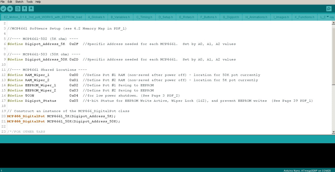
--- FIRMWARE ---
![]()
I also hit a new milestone in thefirmware today (yayyy) and got the 2nd digipot fully functional! It's a second IC with a different value (50K) to be used for controlling accelleration with the stock rheostat. I can't wait to try out some smoothed speed slopes with it. ^_^Fortunately, I didn't have to dig into edits with the main library, and could get away with just the I2C address change (after using I2C scanner code, I found my digipots were 0x0D and 0x0F). However, my ported firmware needed to have a bunch of variables adjusted and renamed, display and menu updates, etc.
I also added some proper debouncing for the touch slider controls. Funny, it was accidentally "debounced" by the OLED display writes being slow on the same bus. Once I cleaned up the display with less text, the loop sped up *really* fast and killed off my fake debounce ;D so I wrote a bit of code for that and also added touch menu controls and multi-touch! More on that later :)
-
Touch Control Demo!
05/06/2023 at 03:07 • 0 comments -
Touch Sensor Success ^_^
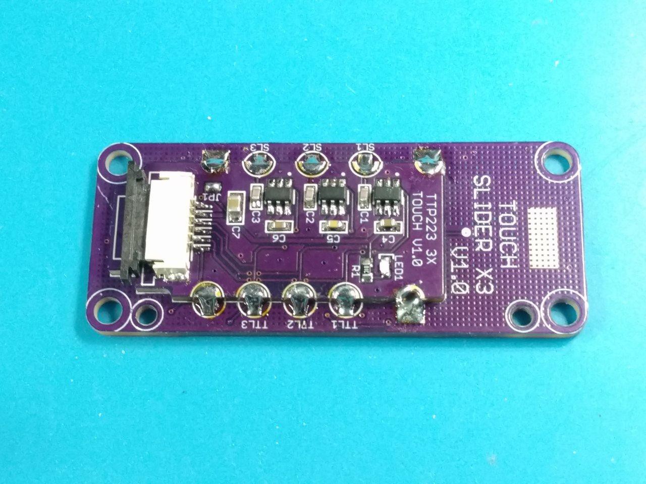
05/04/2023 at 18:16 • 0 commentsThe TTP223 slider control and single touch PCBs came out beautifully - on the first iteration :) See my post below for more of the details and the reference design. Capacitive touch is so fun to work with and (when done right) is incredibly responsive and bug-free! and so much less painful to use.
![]()
The castellation design worked out perfect - 3x duplicate TTP223 modules. This modular design allows me to reuse the slider touch PCB with a different IC, or the ESP32's touch GPIOs later. The FPC-6 1.0mm connector is nice and durable and makes cable management and mounting a breeze :)
![]()
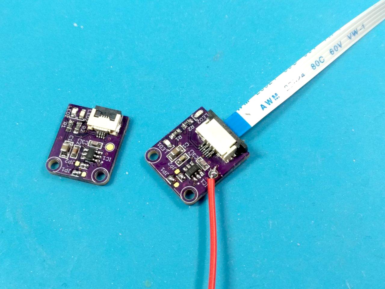
The next PCB I assembled was the single touch version. As mentioned in my previous post, I wanted to have more features than the cheapo ones that are already available. I also prefer the flexibility (no pun intended) of using Flat Flex Cables.
Unlike the slider, I did not design a special touch PCB for these. The red wire goes to a piece of copper for the touch sensor. I found that this (not surprisingly) made the triggering a lot easier to do, as there wasn't the surrounding ground plane or the hatched ground underneath to break up stray capacitance.
In order to keep the copper from triggering too easily, I changed the parallel touch capacitor from the frequently used 22pF value to a higher range of 47pF. the datasheet for the TTP223 mentions that higher values reduce sensitivity, and this worked like a charm. Problem solved.Now it's time to 3D model and print a panel mount case...
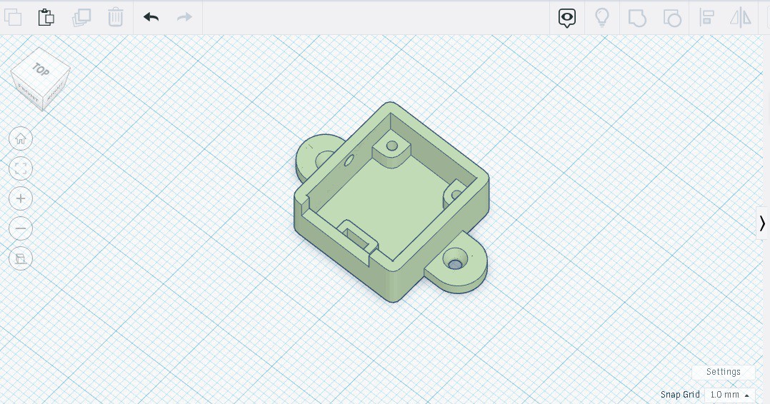
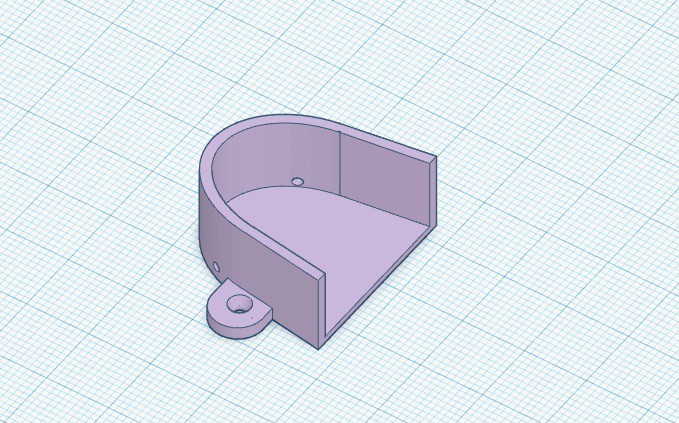
![]()
![]()
![]()
Took a couple iterations to get the FFC cutout and support, but it's solid now!
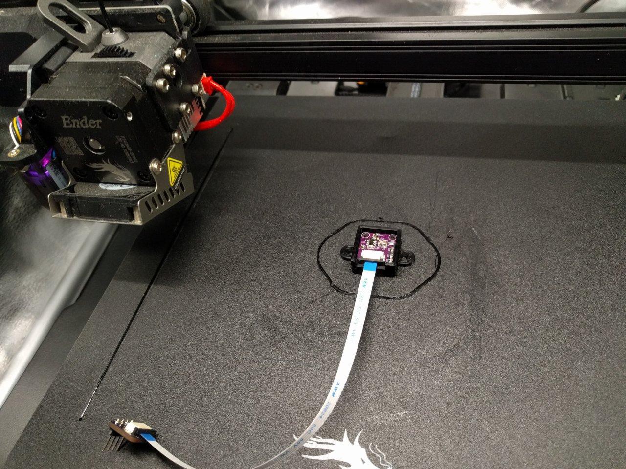
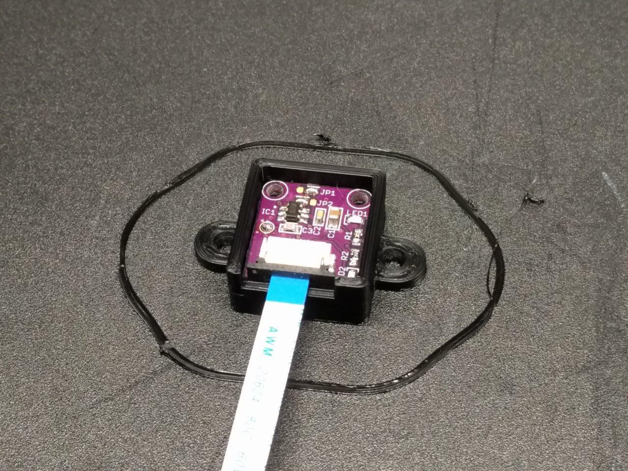
![]()
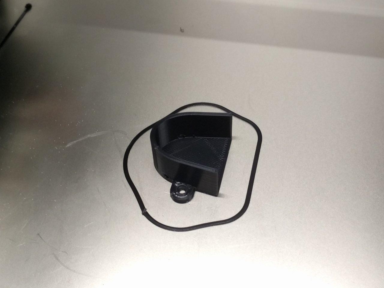
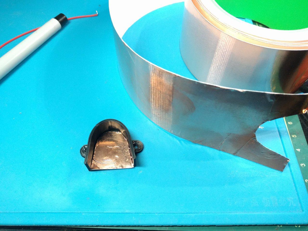
Then I had some fun making a 3D model to match my actual thumbprint. I love stuff like this - I thought this is the kind of customization that disabled people deserve to have with our medical aids. and why not? I took measurements, modeled, and 3D printed this in about an hour :)![]()
![]()
![]()
Here you can see I used the roll of adhesive copper foil to cut out a matching touch sensor. It's crude, but it does the job! I also modeled the case to have holes in it for the attaching wire.
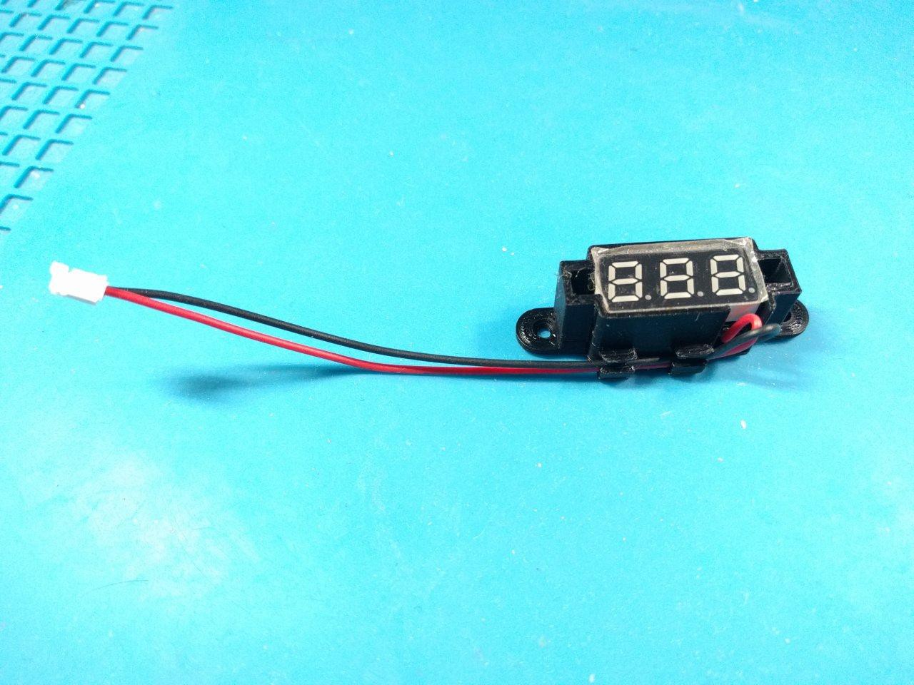
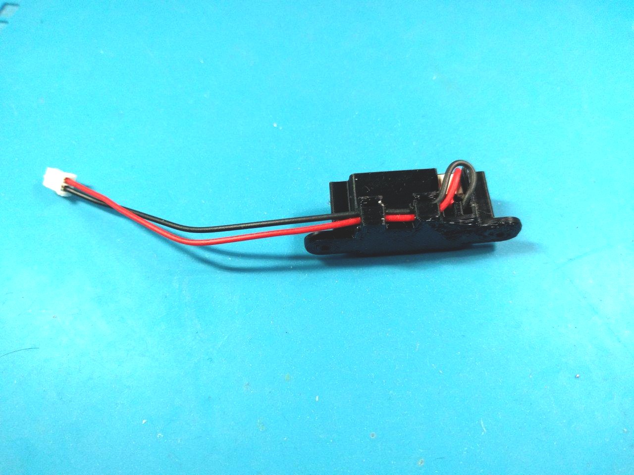
After this, I updated my LED voltmeter case. It's also a panel mount now, with a nifty cable strain relief as well :)
![]()
![]()
![]()
With that done, I realized I needed some panel mount brackets to lock in my testing breadboard. Sure, it has a big slab of adhesive on the back, but I try to avoid hard to remove adhesives during prototyping whenever possible.
![]()
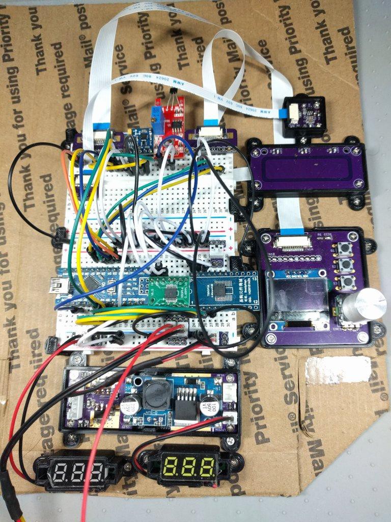
Now it's time to assemble this funky set up... Ideally I'd use a piece of plywood to screw everything into, or an enclosure case of some sort. I didn't feel like 3D printing a huge case that I will grow out of in a week of R&D. And I was feeling too lazy to take out my miter saw to do plywood cuts, so...![]()
The entire thing is assembled on two layers of cardboard - USPS flat rate cardboard! Free at the post office ^_^ my M2 wood screws threaded into it surprisingly well....now, it's time to update the firmware...
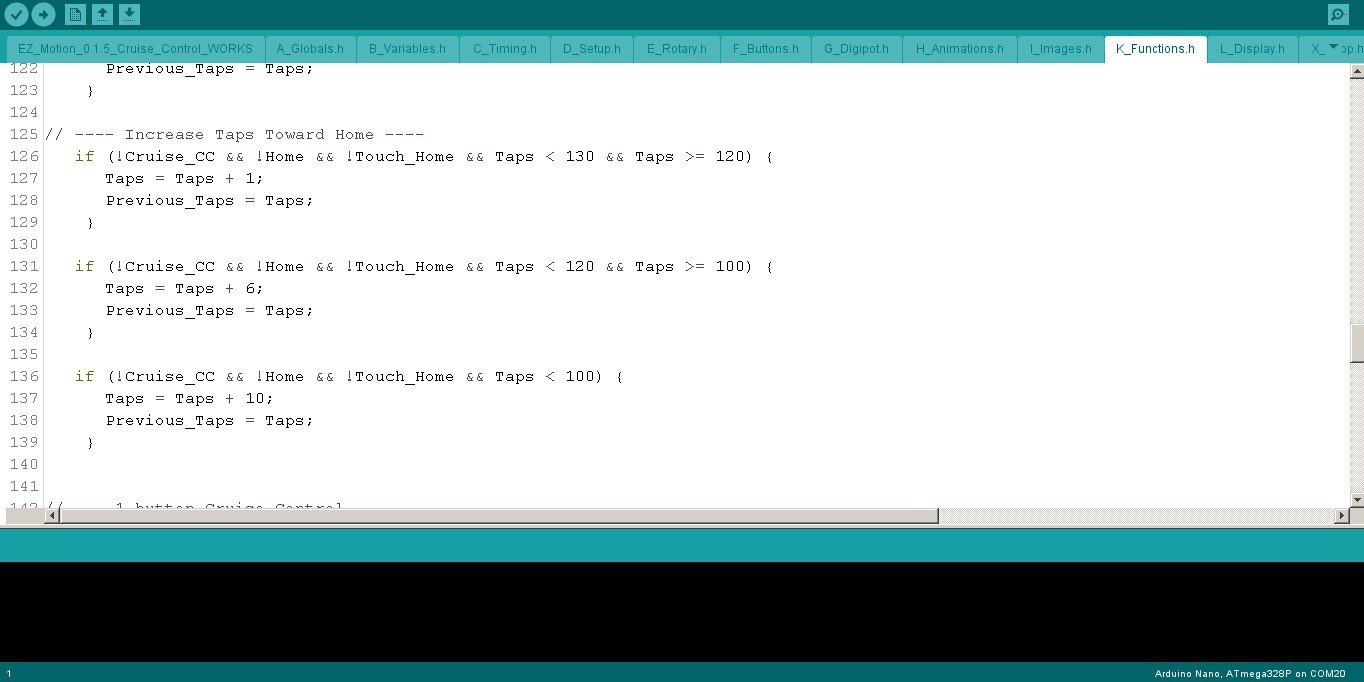
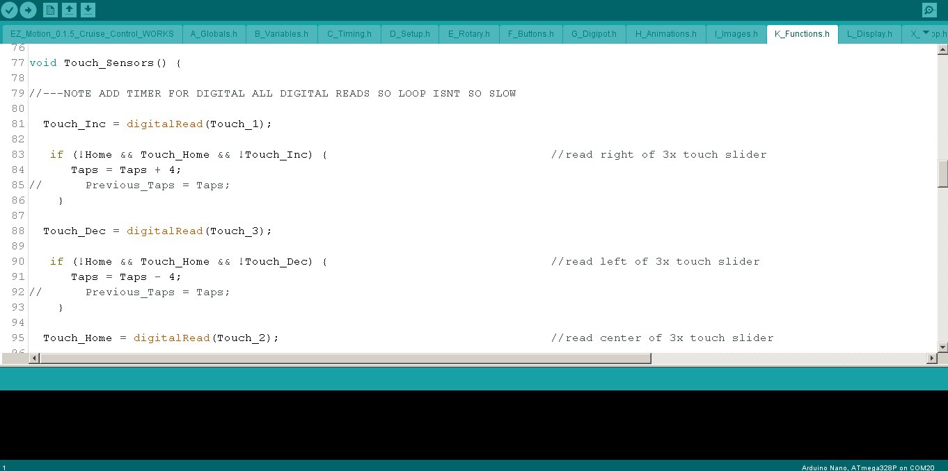
![]()
![]()
Nothing too fancy here - added some new globals for the touch I/O and variables [not shown].
The copper foil touch sensor definitely benefited from some denouncing, which took a little bit of fiddling with to get the cruise control to trigger just right. It works *really* nice now...
The slider code was easy to get working, but will take some time to get it perfected. I'm just guesstimating how much the pot values affect speed. It's logarithmic though, not linear, so it's a spotty business. I have to give it some TLC later on, although I'm hoping I can avoid a lot of the work by simply adjusting acceleration with the rheostat dummy load to another digipot (more on that later).
...Now it's time to take it for a spin! ^_^
[to be continued...]
Wheelchair EZ-Motion
Hacking wheelchairs / mobility scooters to make them more accessible to folks with more than 1 disability