 Mark B Jones
-
1Step 1: Gather components to build the float box (containing ‘Lemon’ M5 Stick C Plus)
IP67 Float Box, M5 Stick Watch Plastic Case or any suitable project box for the electronics, RS485 PCB and 4-pin JST female connector, GPS PCB and antenna, Voltage Boost Regulator PCB, M5 Stick C Plus, 90 degree 8 x pin header, 5cm Grove cable, 25cm 4-core cable with USB A plug, 1 x USB-C prototyping plug, 2 x Micro JST 2-way sockets (male), 4-core flat cable.
-
2Step 2: Setup a free Qubitro account.
Setup a free account at Qubitro.com, create a new project called ‘mercator-origins’ and create a new device called ‘M5.Lemon’. Click on Overview / Connection Details to get the MQTT server host/port and device username/password and then goto Settings to get the Device_ID and Device_Token. These credentials will be used in step 13.
-
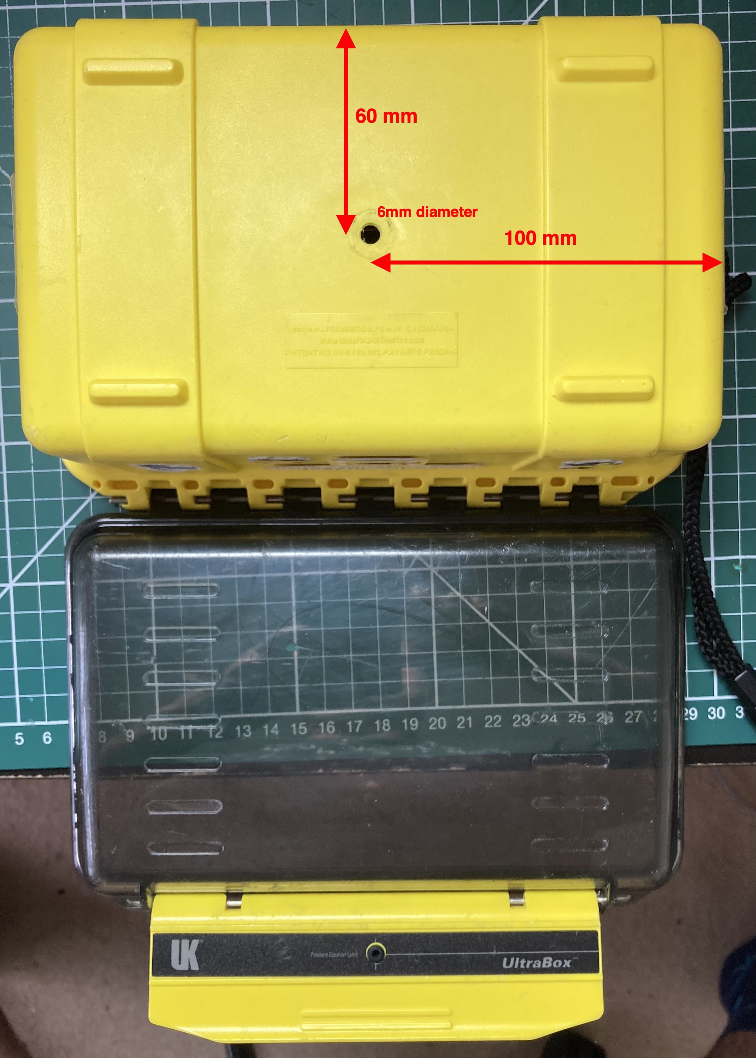
3Step 3: Drill the float box
Drill using a 6mm bit from the outside of the base of the IP67 float box through to the inside, aiming for the centre of the base of the box. 100mm x 60mm offset.
![]()
-
4Step 4: Prepare the USB-A Power Cable
Cut to 25cm a spare USB cable, keeping the USB-A plug/cable section. At the bare cable end, strip the wires back 7cm Identify the red and black wires which correspond to 5V and 0V/GND connections. Verify with a multimeter that the voltage across these wires is 5V when plugged into a USB power source. Ensure the wires do not touch when measuring!
-
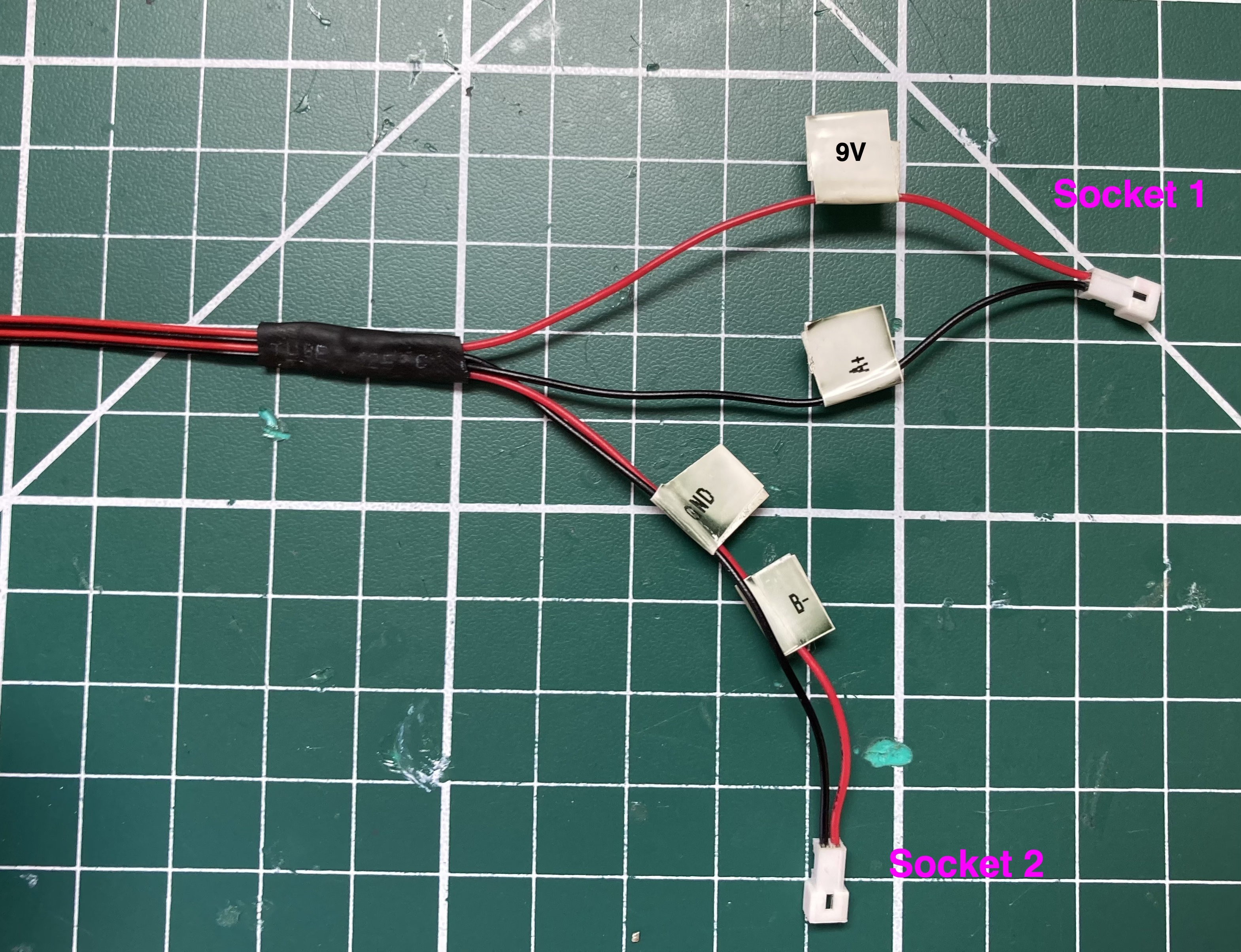
5Step 5: Prepare the 4-core float signal cable
Cut to length 23cm of 4 core stranded wire (eg 26 AWG) and solder the Micro JST male sockets with flying leads as described below. Use dual wall heatshrink to insulate and protect/seal the solder joints – 2mm diameter for each wire connection and 4mm for the outer jacket. <br><br>
Socket 1 connects to:
* 9V power (RED)
* A+ (RS485) signal (BLACK)
Socket 2 connects to:
* B- (RS485) signal (RED)
* 0V/GND (BLACK)
Label the wires for future reference. The 4-core flat cable used in the photo connects as follows:
4 Core Red outer wire: 9V connects to Socket 1 red wire
4 Core Black middle wire: A+ connects to Socket 1 black wire
4 Core Red middle wire: B- connects to Socket 2 red wire
4 Core Black outer wire: 0V connects to Socket 2 black wire
![]()
-
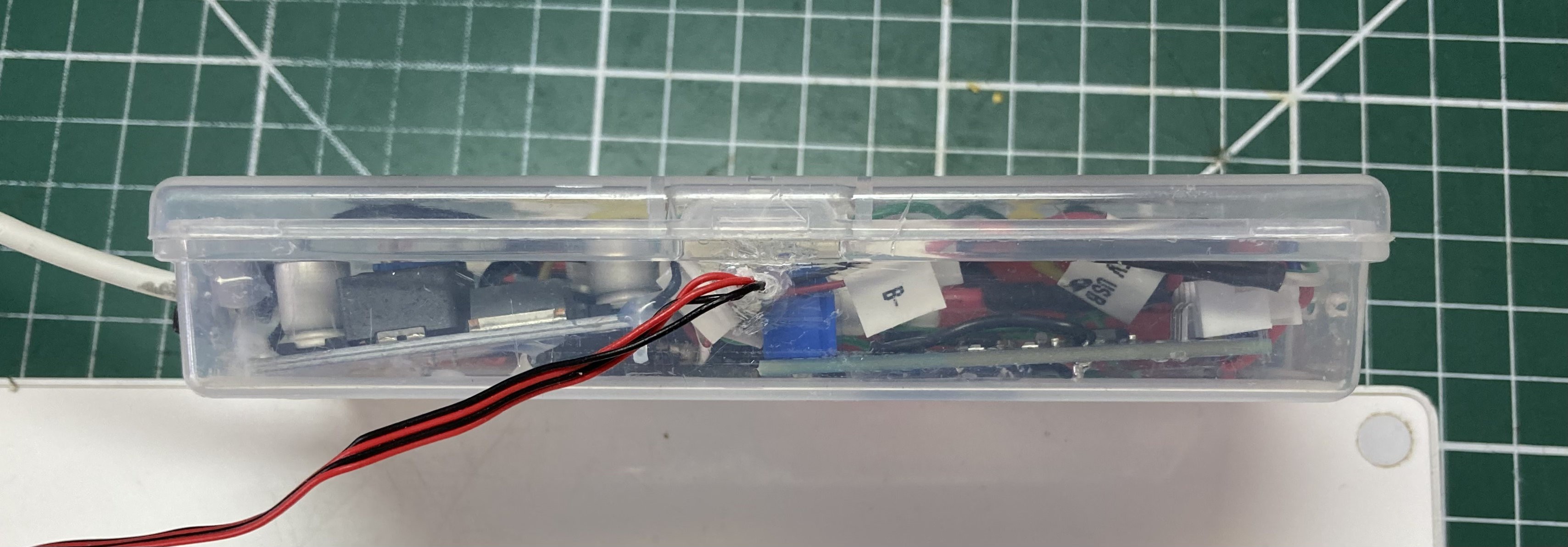
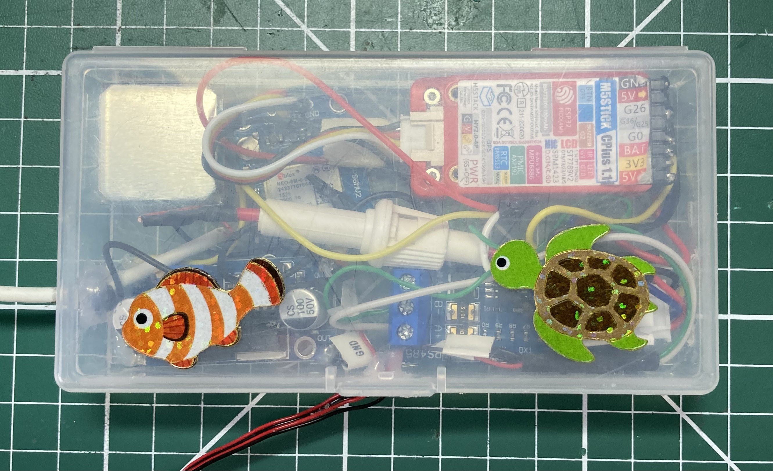
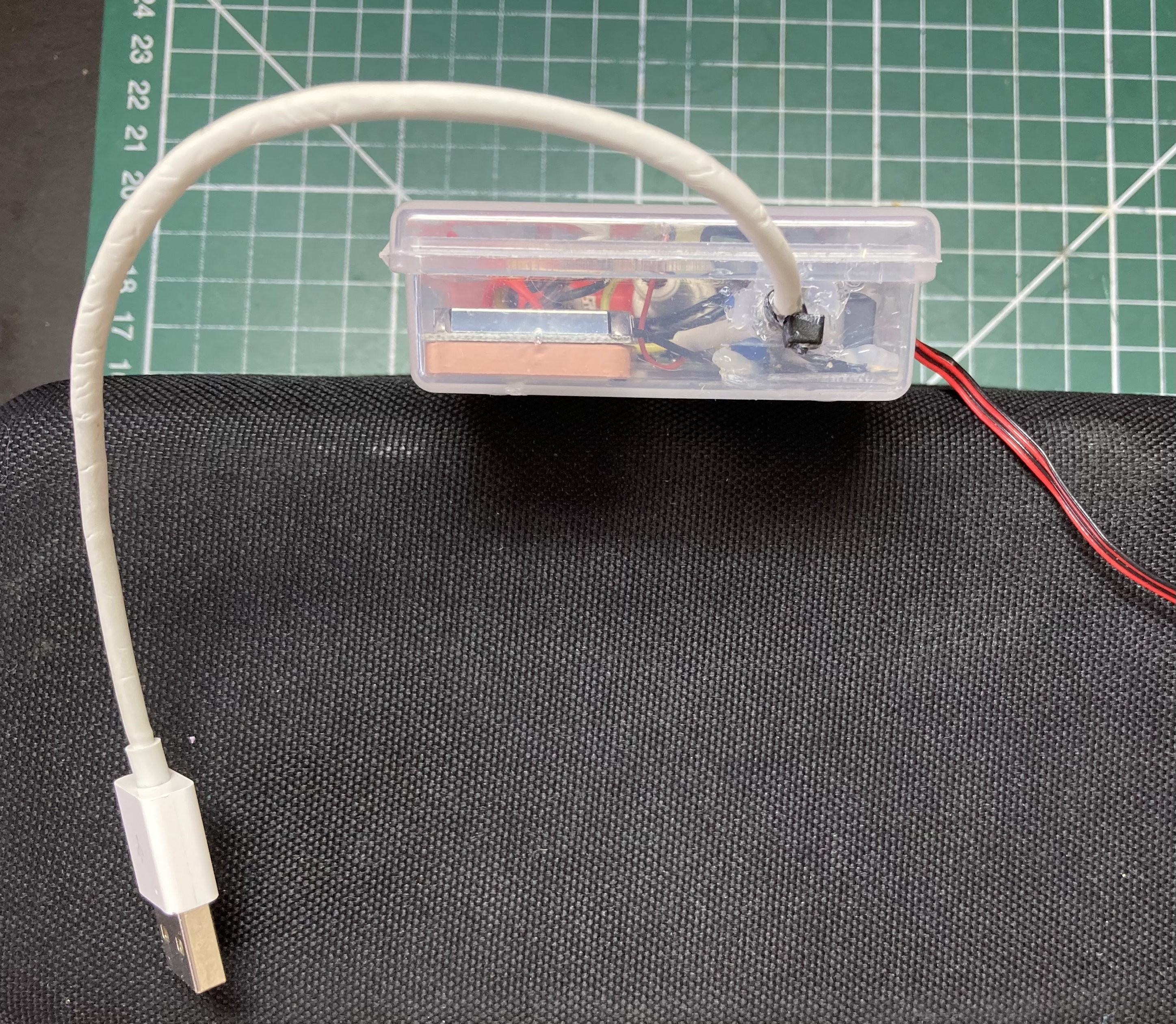
6Step 6: Make cable exit holes in enclosure.
Take the M5 Watch plastic enclosure case and make two holes:
- On the left side edge, with the case opener nearest to you, make a hole large enough for your USB cable (bare end, eg 3mm) to pass through. Hot glue the cable into the left side (when viewed from the top/front) of the enclosure, keeping 6cm of cable/wire inside for making internal connections.
- On the front edge where the case opens, make a hole centre to the case, large enough for the 4 core signal cable to pass through, eg 3mm length x 1mm height. Hot glue the 4-core cable into the enclosure leaving 5cm wire within the enclosure for making further connections.
![]()
![]()
![]()
![]()
- On the left side edge, with the case opener nearest to you, make a hole large enough for your USB cable (bare end, eg 3mm) to pass through. Hot glue the cable into the left side (when viewed from the top/front) of the enclosure, keeping 6cm of cable/wire inside for making internal connections.
-
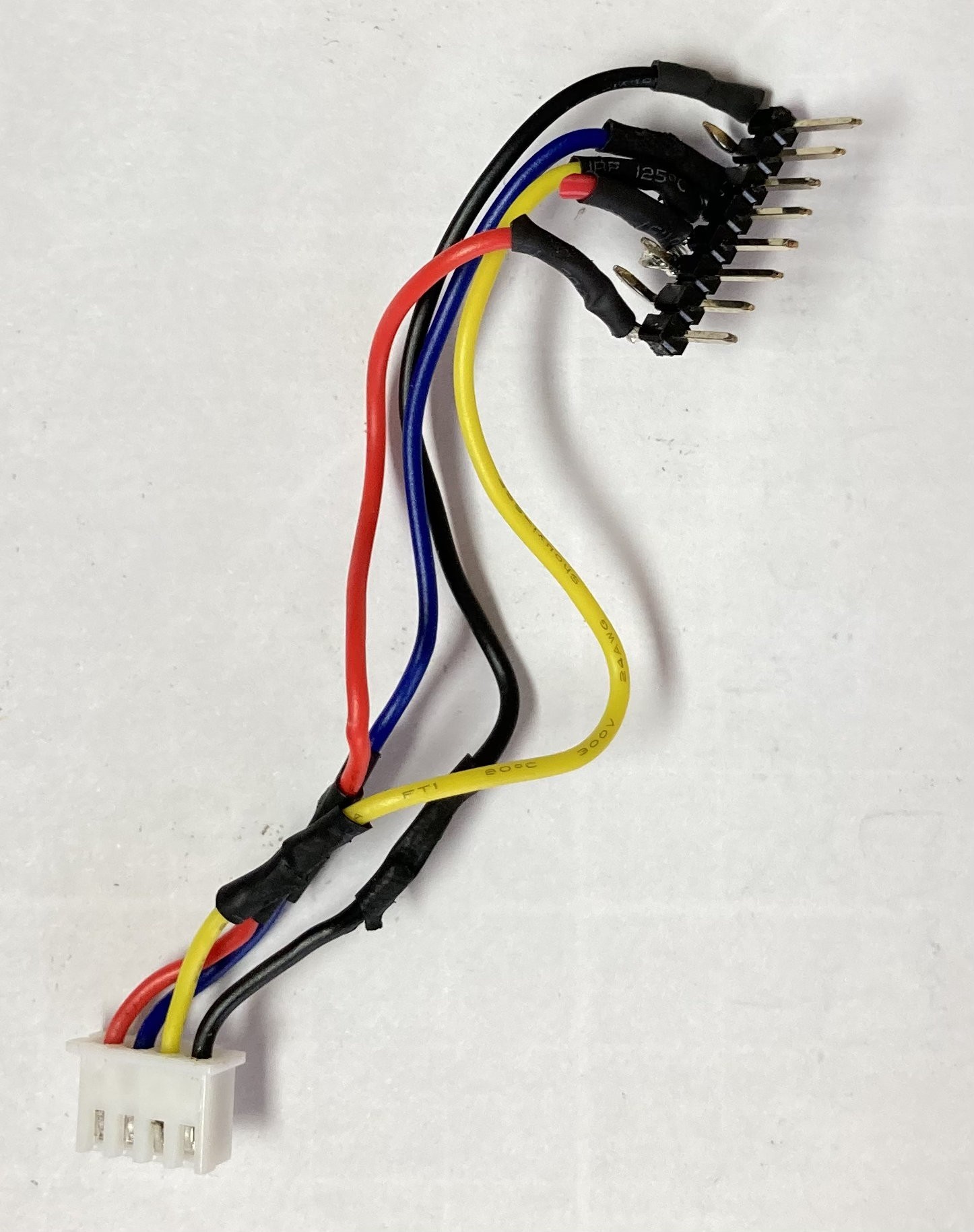
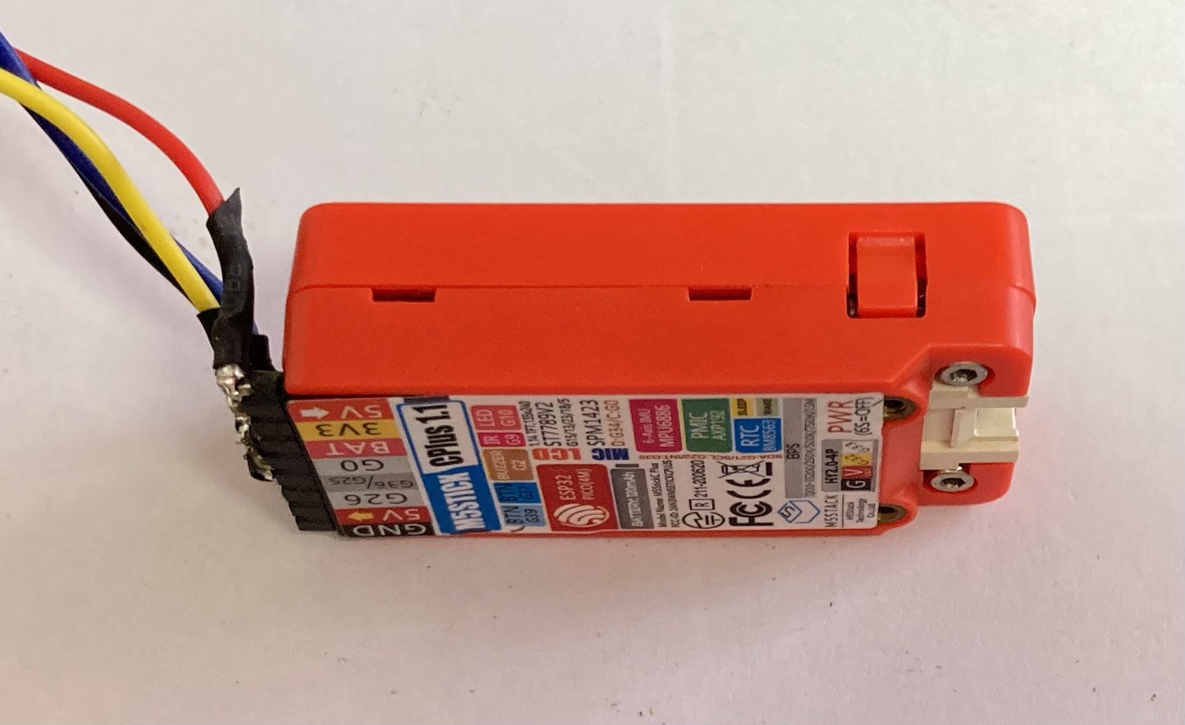
7Step 7: Solder RS485 UART / Header Assembly
Solder RS485 UART wiring assembly which connects the GPS PCB to the M5 Stick 8-pin HAT header connector. Approximate cable length is 8cm. Modify the JST pin connections if your RS485 PCB has a different header layout. Note that the 90 degree header needs to be oriented so that the header pins point down towards the M5 Stick display as per the photo.
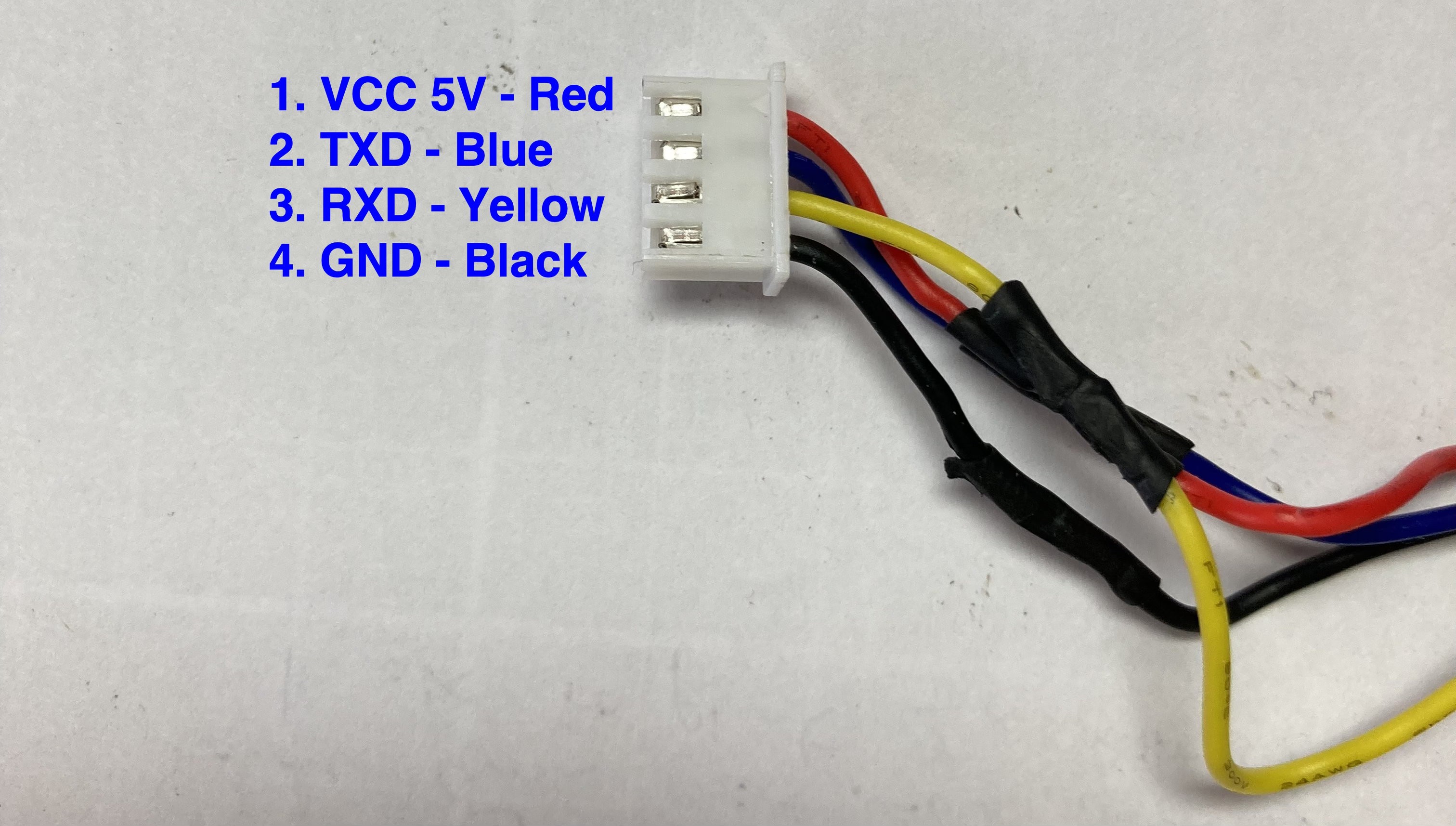
VCC JST-pin-1 RED HAT Header-pin-8 5V
TXD JST-pin-2 BLUE HAT Header-pin-3 GPIO 26
RXD JST-pin-3 YELLOW HAT Header-pin-4 GPIO 36
GND JST-pin-4 BLACK HAT Header-pin-1 GND
![]()
90 degree header pins:
![]()
4-pin JST female connector
![]()
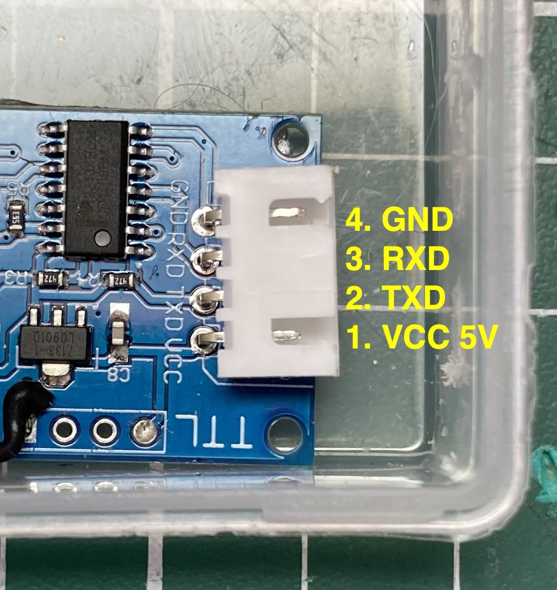
RS485 PCB JST pin layout
![]()
M5 Stick C Plus Rear View
![]()
M5 Stick C Plus Oblique View - note the 90 degree header bend is towards the display side of the Stick.
![]()
-
8Step 8 – Solder GPS Module wiring
Solder the Grove connector with 5cm cable to GPS PCB and connect the antenna. Mount the GPS and antenna in the top left corner of the enclosure as per photo, eg use 1mm nano/gecko tape for mounting. See M5 Stick photo to check colours on grove cable match the pin guide on the back of the Stick – don’t mount the stick at this stage, you can disconnect the stick after making the check.
VCC GPS-pin-1 RED Grove-pin-3 5V M5 Stick
RX GPS-pin-2 YELLOW Grove-pin-2 TX GPIO 32 M5 Stick
TX GPS-pin3 WHITE Grove-pin-1 RX GPIO 33 M5 Stick
GND GPS-pin4 BLACK Grove-pin-4 GND M5 Stick
Solder the grove cable wires to the GPS PCB
![]()
Note the colour of the Grove cable wires, check that your cable has the same colour coding.
![]()
-
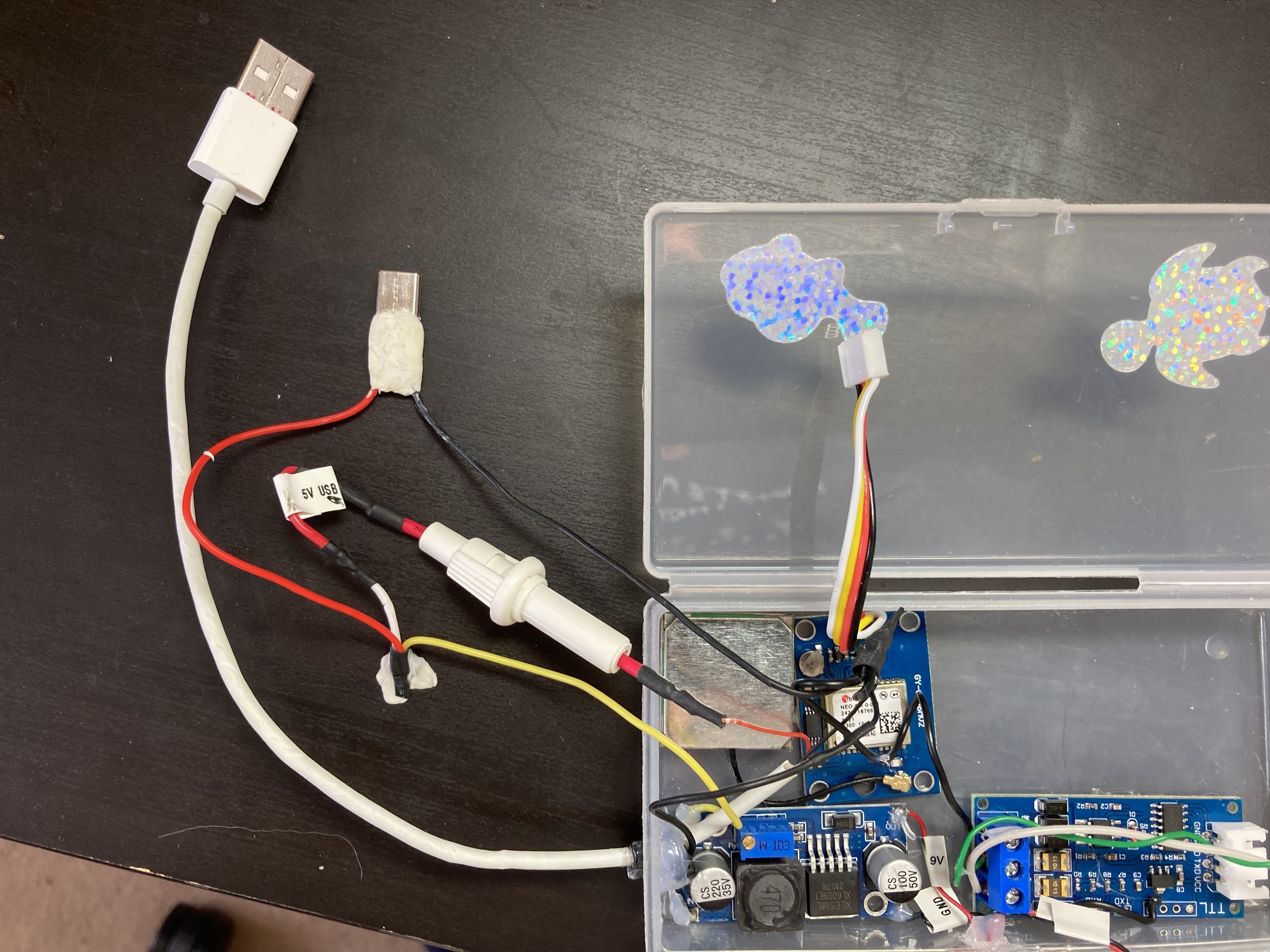
9Step 9: Connect and mount the RS485 PCB to the 4-core signal cable
Connect the RS485 PCB to the signal cable (blue connection block on left side), connect A+ signal wire to A+ screw terminal, connect B- signal wire to B- screw terminal, and USB ground to GND (Chinese lettering) screw terminal. Solder a black wire between GND on the blue connector on the left to GND on the UART socket (a pcb GND pad is used below). Mount the RS485 PCB in the lower right of the enclosure using 1mm nano tape.
-
10Step 10: USB-C Wiring Assembly
Solder 5V and Ground/0V wires to a prototyping USB-C plug (to power the M5 Stick C Plus) and use moulding rubber putty (white in photo) to insulate and mechanically protect the connections. Solder an extra wire (yellow in the photo) to the 5V supply for use by the voltage boost regulator, to be assembled in the next step.
Solder/connect the 5V supply wire to a 5 Amp fuse in a holder, so that both the USB-C plug and the voltage booster are protected by the fuse. Solder the other side of the fuse to the 5V USB-A power supply wire. Solder the USB-A cable ground wire to the ground wire of the USB-C plug and also to the Blue Connector Ground Pin on the RS485 PCB.
![]()
"Mercator Origins": Sat Nav & Telemetry for Divers
Want to map your dive? Want to navigate like a pro? Even if you are vision-impaired, this will empower you to navigate our underwater world.


Discussions
Become a Hackaday.io Member
Create an account to leave a comment. Already have an account? Log In.