 Mark B Jones
-
11Step 11: Connect up the Voltage Boost Regulator and Mount
Take the Voltage Boost PCB and make the following connections:
Out+ to 9V wire of 4-core cable.
Out- to GND wire of 4-core cable.
In+ to the extra 5V wire from step 10 (yellow in photo).
In- to USB-A cable ground wire.
Ensure the Out+ connection ONLY connects to the 9V 4-core cable wire that is terminated in a micro JST 2-way male connector. This supply line is only used for sending power to the navigation pod under the surface, it is not used for powering any devices inside the float box.
Mount the voltage booster regulator PCB in the bottom left of the enclosure using 1mm nano tape.
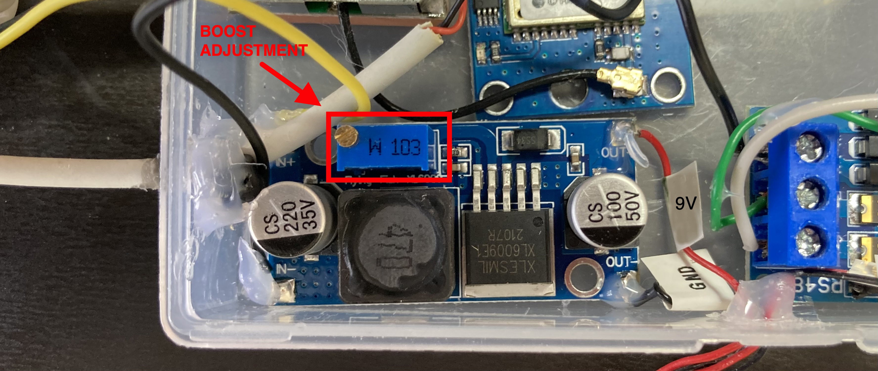
Positions of IN+, IN-, OUT+, OUT- marked with arrows below:
![]()
-
12Step 12: Voltage Booster Regulator Adjustment to 9V
The voltage booster needs to have its output voltage adjusted to 9V. Having used a continuity tester to ensure all existing connections are sound, connect a 5V power source to the USB-A plug. Check for 5V across In+ and In- terminals. If no volts present then check the fuse is present and not blown and check your wiring again.
Now that the input voltage has been confirmed, measure the voltage across the Out+ and Out- terminals on the voltage booster, it should be greater than 0V. Now adjust the wire-wound potentiometer using a flat head screwdriver until 9V is measured on the output.
Confirm that 9V is also available on the micro JST 2-way male sockets at the end of the 4-core signal cable (Socket 1 red wire is 9V, Socket 2 black wire is 0V/GND).
![]()
-
13Step 13: Upload mercator-origins Lemon code to the M5 Stick C Plus
Download the repo https://github.com/scuba-hacker/mercator-origins-lemon and build/ and rename the mercator_secrets_template.c to mercator_secrets.c. Edit the ssids and passwords for up to three internet connections, both for uploading the code using OTA and for whilst the system is being used on water (eg your WiFi/4G hotspot). Also edit your user/connection credentials for the Qubitro IoT internet server from Step 2.
Build and upload the code to the M5 Stick C Plus using the Arduino IDE via a USB wired connection before mounting the Stick in the enclosure in the next step.
Lemon Arduino library dependencies
M5StickCPlus
ESP32Ping (Marian Craciunescu – not ESPping lower case) https://github.com/marian-craciunescu/ESP32Ping
QubitroMqttClient
AsyncTCP
ESPAsyncWebServer
AsyncElegantOTA
-
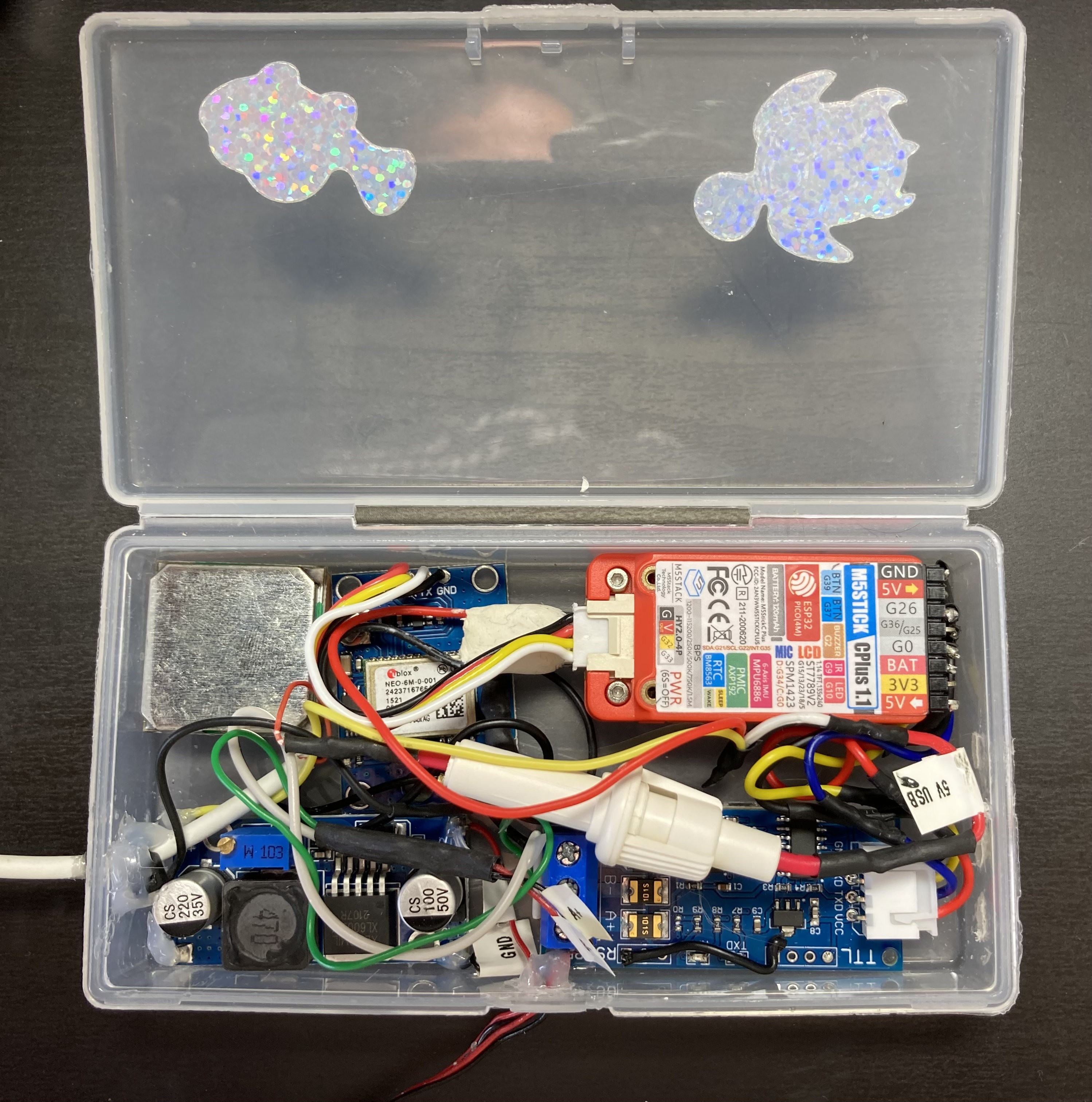
14Step 14: Mount the 'Lemon' M5 Stick C Plus
Insert the USB-C Plug to the M5 Stick C Plus, followed by the Grove plug for the GPS PCB also into the Stick. Insert the 90 degree header to the Stick and mount the Stick display down in the top-right corner of the enclosure, with grove socket to the left. Use 1mm nano tape for mounting. Avoid placing tape over the display.
Connect the JST 4-way female plug (opposite end of the header pins) to the RS485 UART socket.
![]()
-
15Step 15: Fuse placement and closing the enclosure
Position the fuse holder in the middle of the enclosure and ensure no wires are caught whilst closing the box. The electronics enclosure for the float is complete.
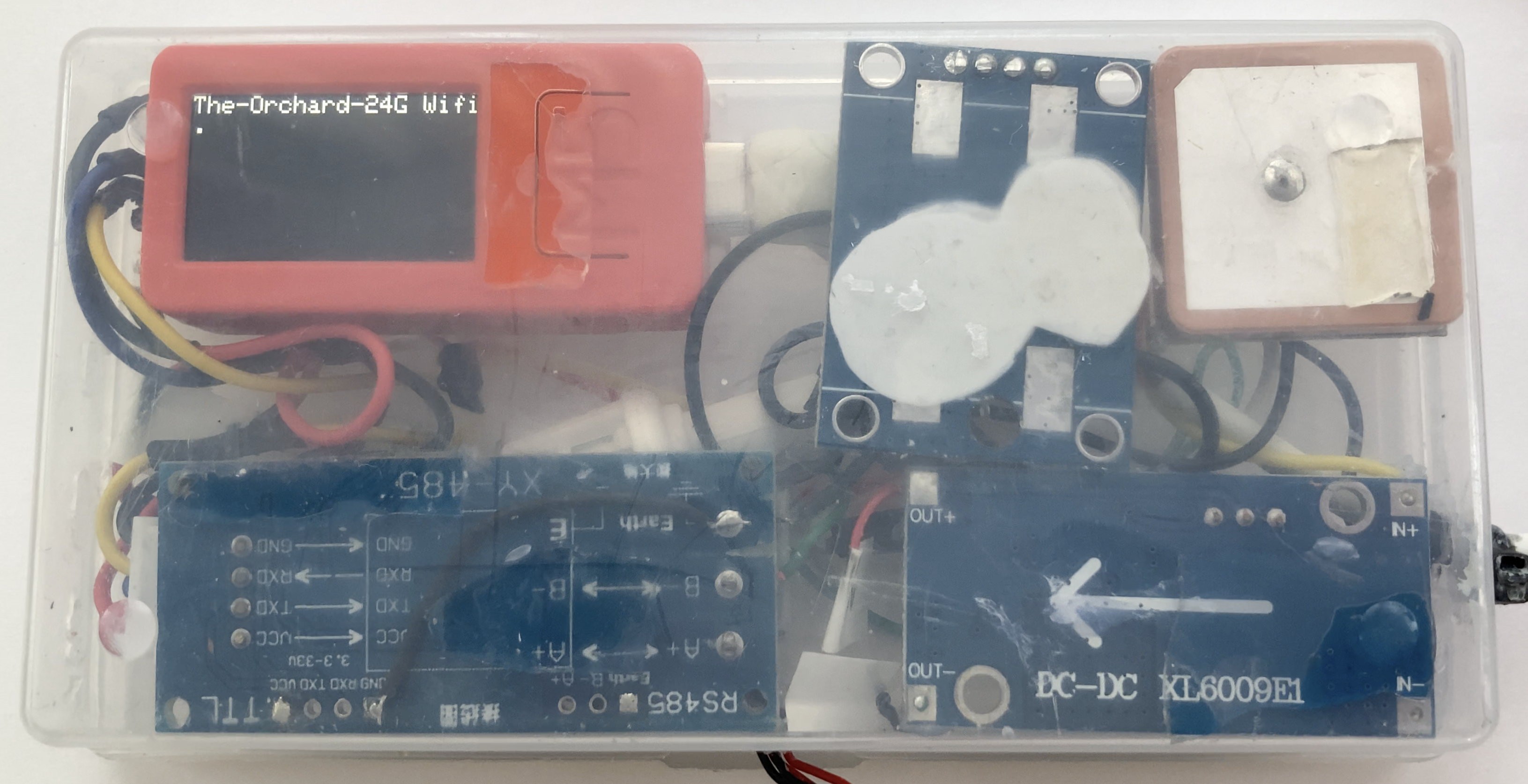
![]()
Front of the enclosure. Opens inwards into the float box.
![]()
Rear of the enclosure. This side is mounted to the underside of the float box lid so that the display is visible when the lid is shut.
-
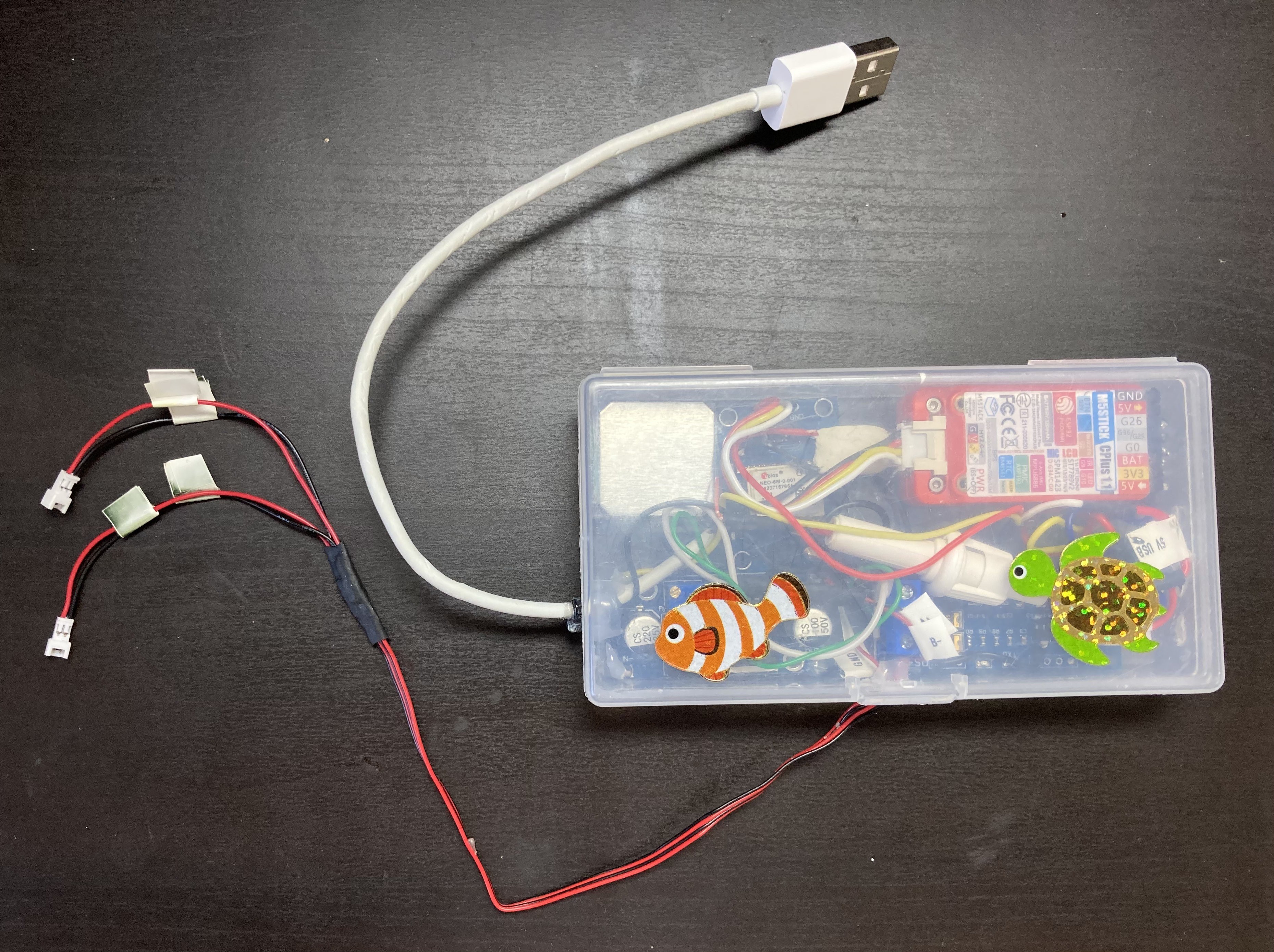
16Step 16: (Optional) Switch harness for powering on/off the enclosure
To build an external to the enclosure (but internal to the float box) power switch, solder together a USB-A plug, a USB-A socket and an inline latching Double Pole – Double Throw switch. The switch makes/breaks both the 5V and the GND connections from the USB power source. This is more convenient than inserting/removing USB plug from USB power supply, but there is no problem with attaching a 5V power bank directly to the enclosure if preferred.
In the photo below the USB Power Bank is connected to the USB-A plug on the right.
![]()
-
17Step 17: Lemon M5 Stick C Plus Power On Test
Lemon will try connecting to your WiFi router or hotspot and once connected will display Mac address, IP address and a QR code corresponding to the IP.
Attempt connection to WiFi
![]()
Connected to WiFi
![]()
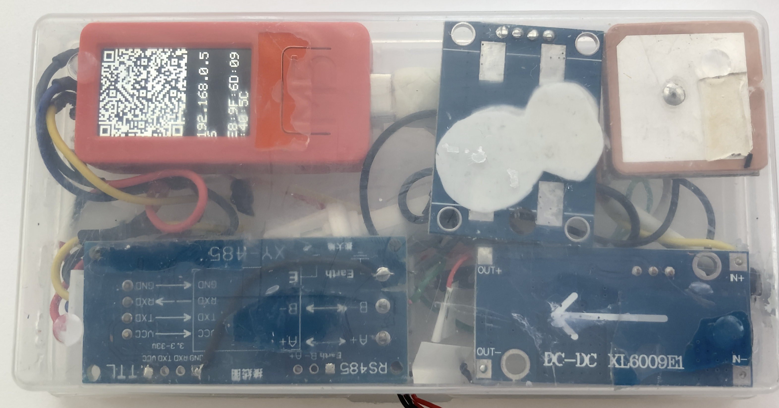
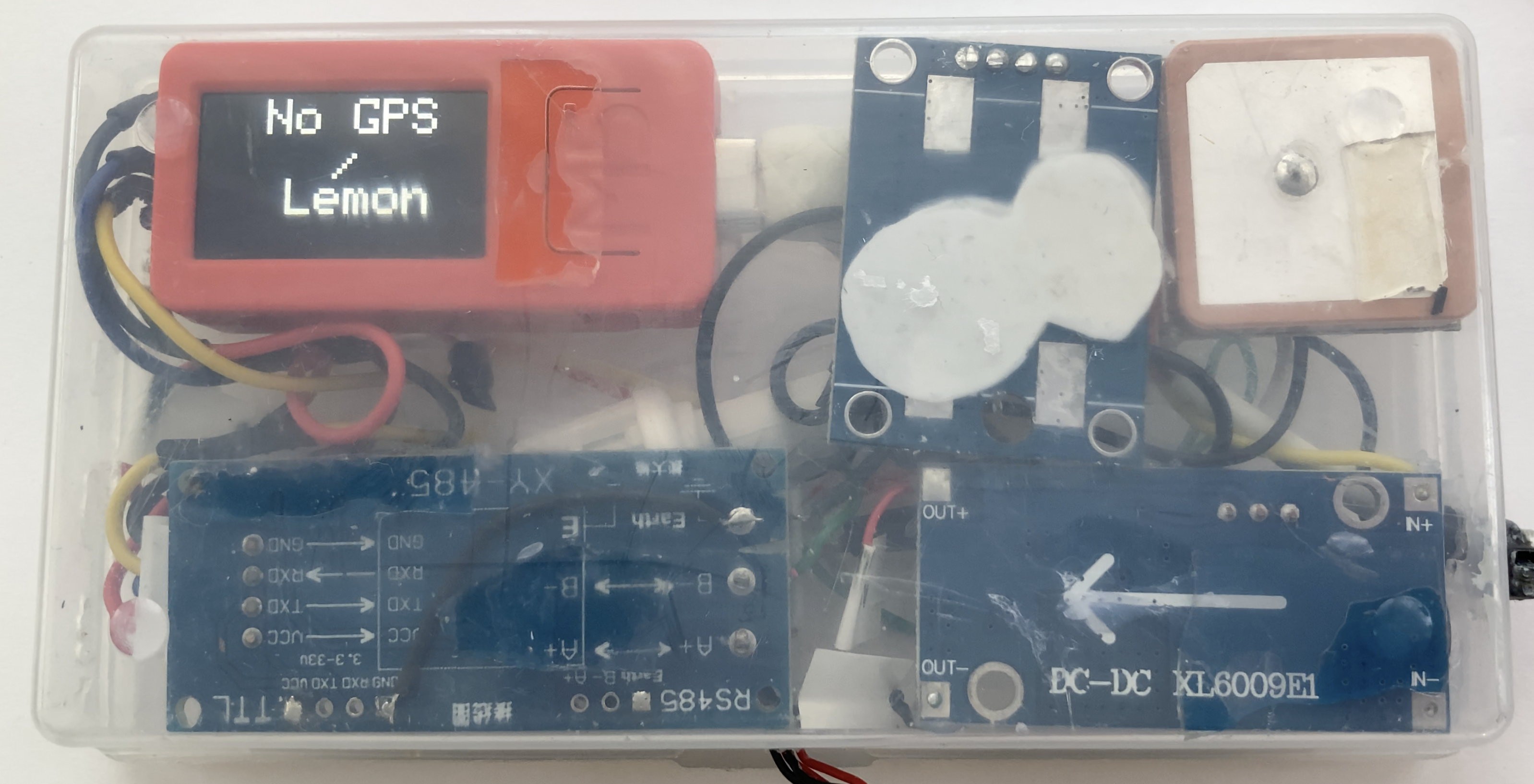
Lemon will then connect to the GPS, start receiving No Fix messages from the GPS and once the GPS has locked onto satellite signals FIX messages will be received. FIX will then be shown on the screen along with communication metrics:
Initially there is no GPS connection
![]()
Almost immediately the first No Fix messages received
The received byte count increments until the first FIX message is received by Lemon.
![]()
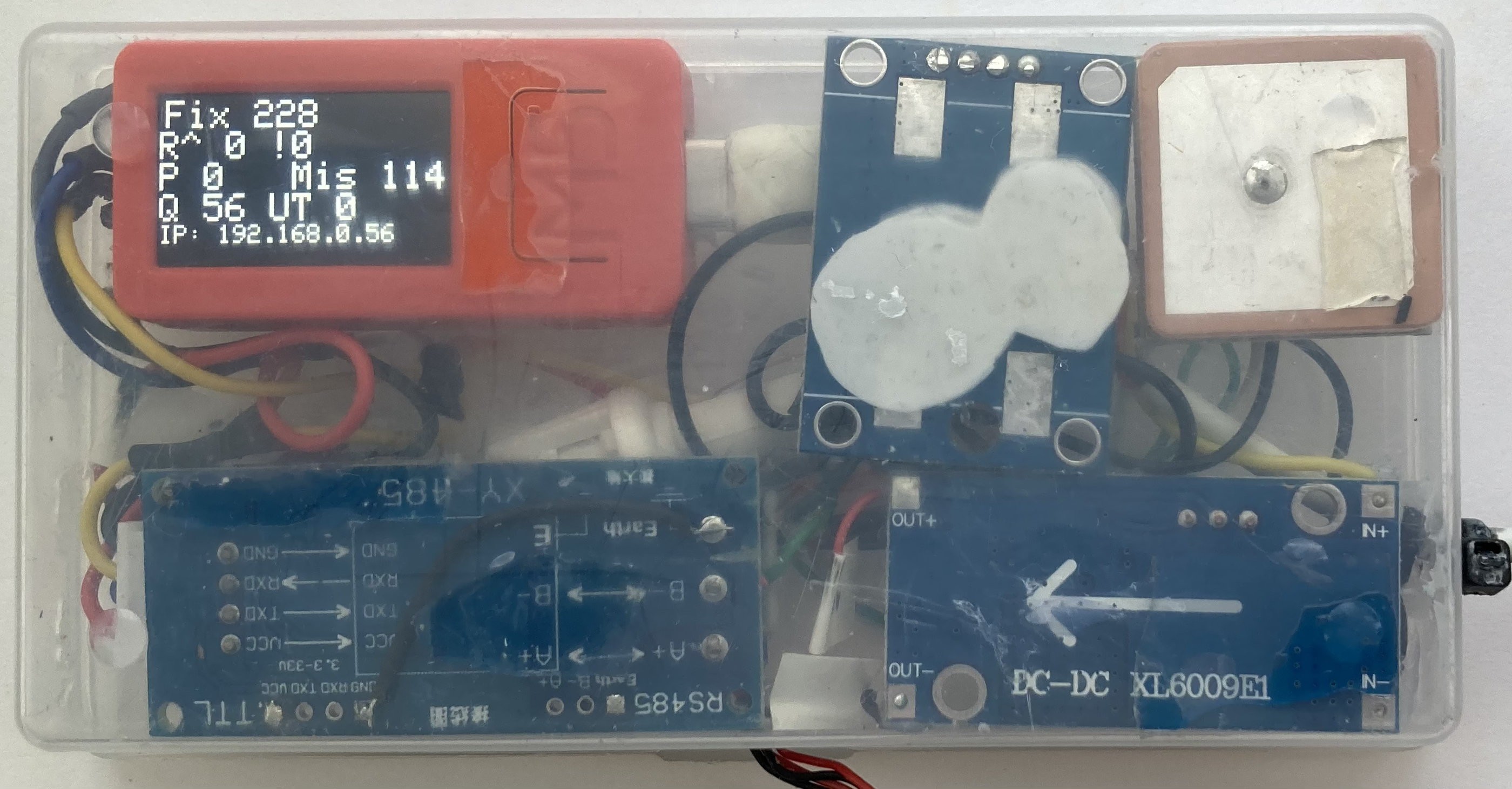
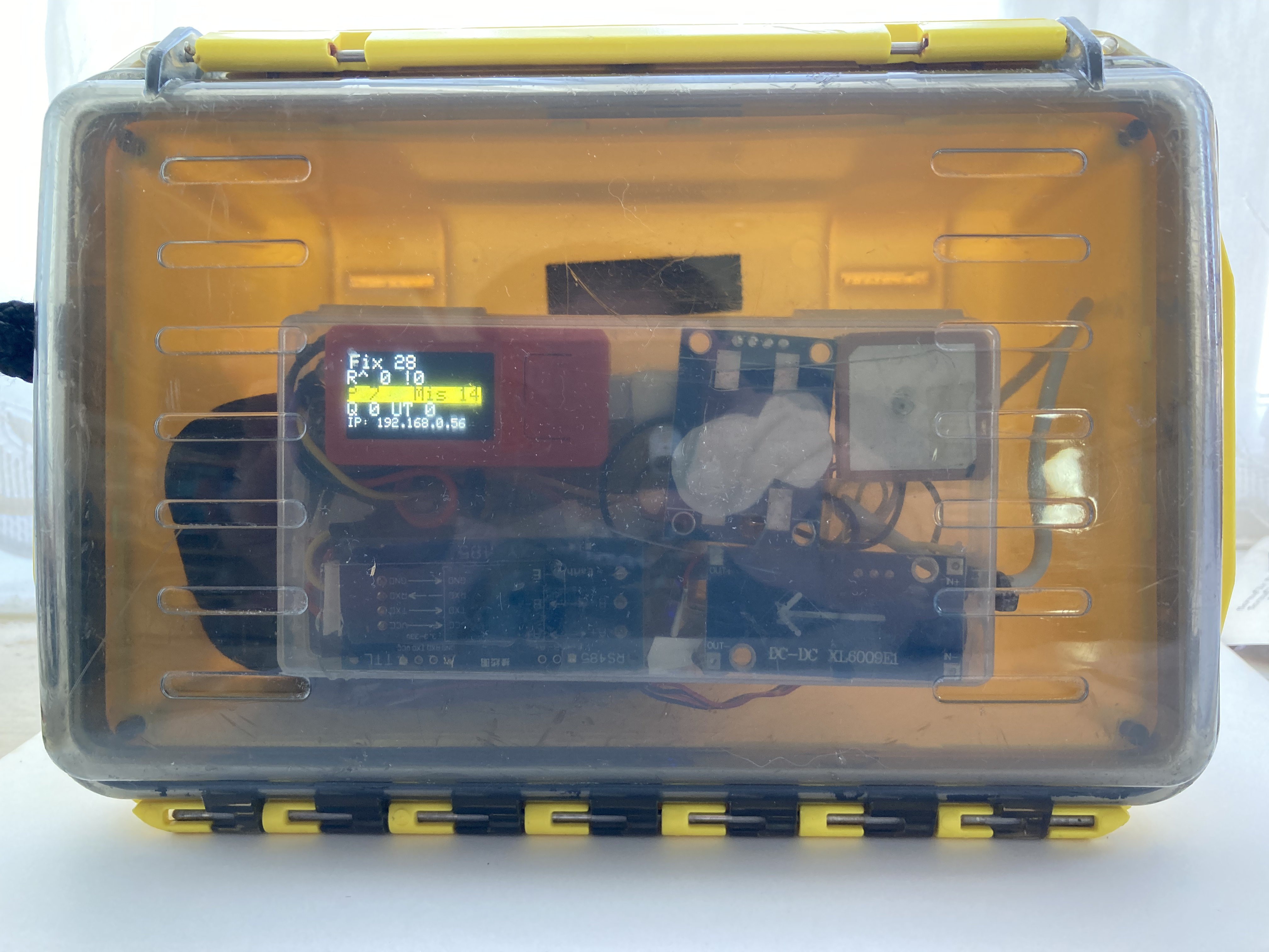
First FIX message received, real-time communication metrics are shown on screen:
![]()
Metrics are:
Fix: number of fix messages received and sent to the RS485 module for transmission to the float.
R^: number of good messages received from Mako (in the navigation pod) under the surface. Zero as the sub-sea cable isn’t connected at this time.
!0: number of bad checksum messages received – again zero.
Mis: number of missed messages expected to be received from Mako in reply. Mako replies once for every two messages received by it, hence for 228 FIX messages sent, 114 replies have been missed in this example.
P: Messages pending to send to internet / Qubitro server.
Q: Number of messages sent to internet / Qubitro server.
UT: Round trip time for message to Mako and reply – zero as no Mako / Nav Pod connected.
IP: LAN WiFi IP for Lemon M5 Stick C Plus.
-
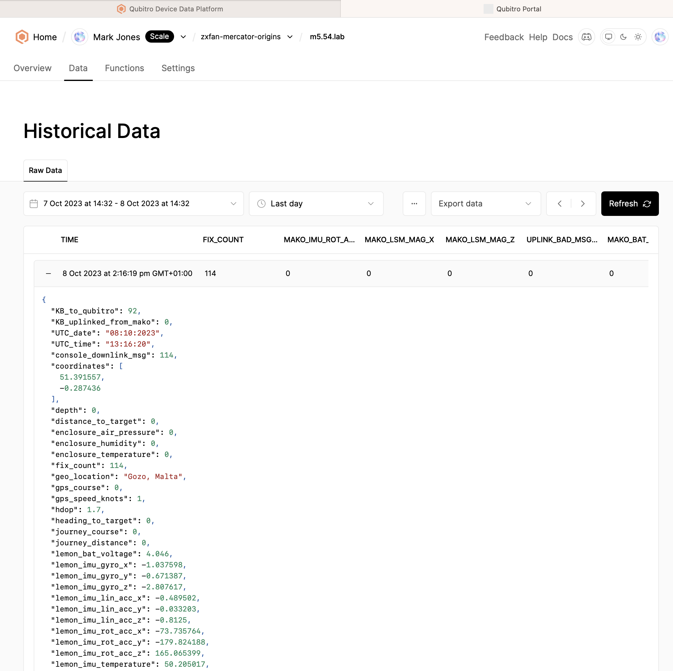
18Step 18: Check Qubitro account for Lemon telemetry upload
Login to Qubitro, select your project, select your device and then select the Data tab to see the messages that have been uploaded. Mako fields will be 0 as the navigation pod is not connected at this stage.
![]()
-
19Step 19: Mount Lemon’s enclosure to the inside of the float box
Use 1 mm nano tape to mount the electronics enclosure to the underside of the lid of the float box, making sure the 4-core signal cable is towards the hinge side of the lid and the top of the enclosure is not too close to the edge so it can still be opened. The image shows the display state prior to connection to the Qubitro server, when there are some messages pending upload and the row is highlighted in yellow. Once connection is established the queue of pending messages is drained and the row reverts to black background.
![]()
-
20Step 20: Gather components for sub-sea cable
Components: Blue Robotics 4-core Ping Cable (11 metres), 2 x 4.5mm WLP-M06 cable wet link penetrators including nuts, o-rings, and silicone seal, plus 2 x cut shake-proof washers, 1 x rubber strain relief boot , 2 x Micro JST 2-way female connectors. 1 x Micro JST 4-way female connector.
"Mercator Origins": Sat Nav & Telemetry for Divers
Want to map your dive? Want to navigate like a pro? Even if you are vision-impaired, this will empower you to navigate our underwater world.


Discussions
Become a Hackaday.io Member
Create an account to leave a comment. Already have an account? Log In.