 Mark B Jones
-
21Step 21: Assemble the cable and wet penetrator terminations
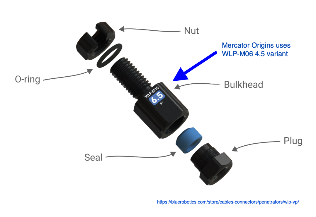
Assemble both ends of the sub-sea cable with a wet link penetrator, allowing 5cm of cable wire to exit each penetrator as per the manufacturer’s instructions at https://bluerobotics.com/learn/wetlink-penetrator-installation-guide/
You may wish to thread the yellow rubber hose protector on (see photo in step 22) before you assemble the navigation pod end of the cable, however this is not necessary as it can be threaded on after assembly with a little effort.
![]()
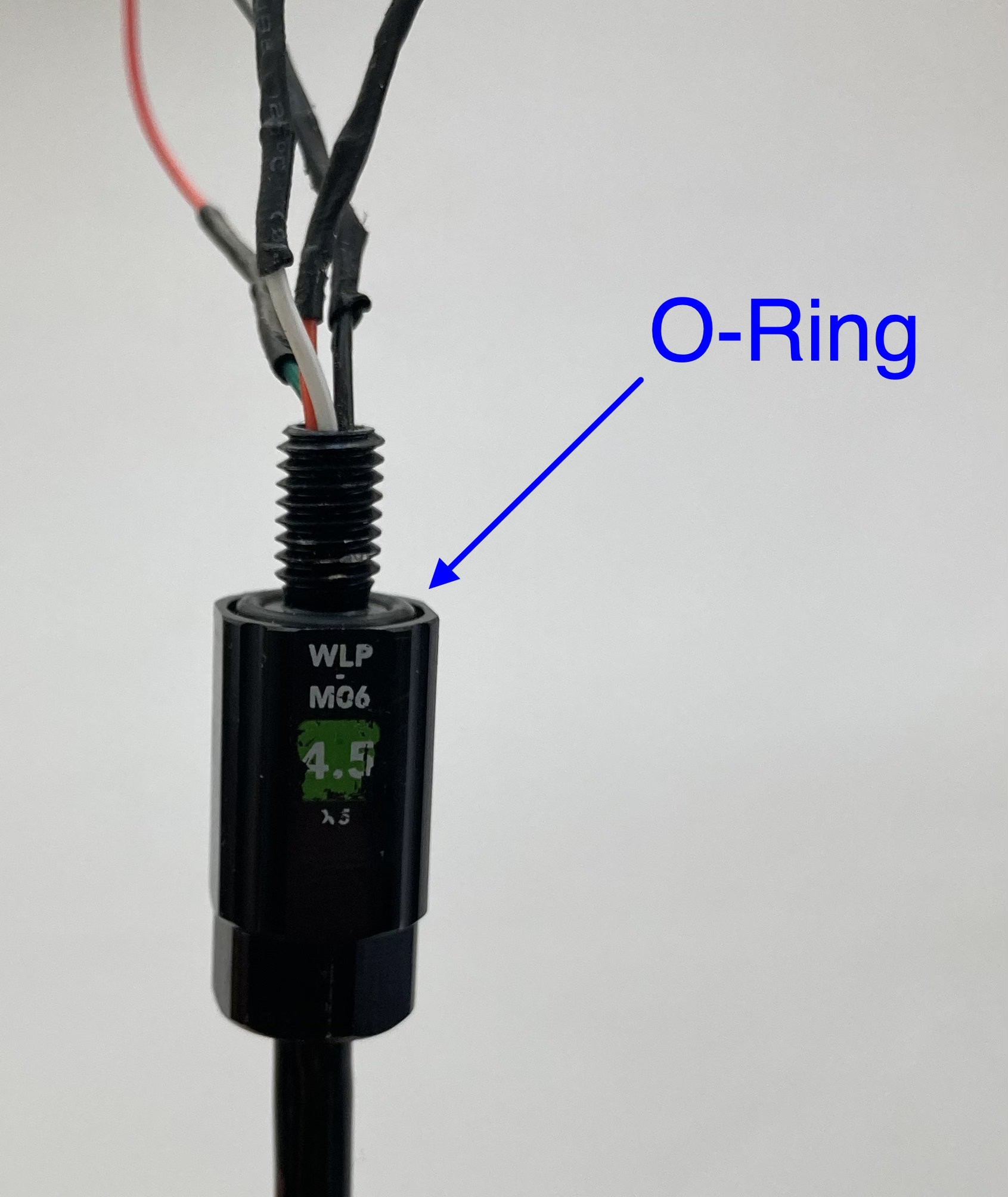
At this stage the cable terminations are individual wires. Ensure the o-rings are seated evenly and that there is no grit on the o-ring or its seat.
Assemble the penetrators on both ends of the cable with individual wires then available for soldering.
![]()
-
22Step 22: Solder the Micro JST female connectors to the sub-sea cable
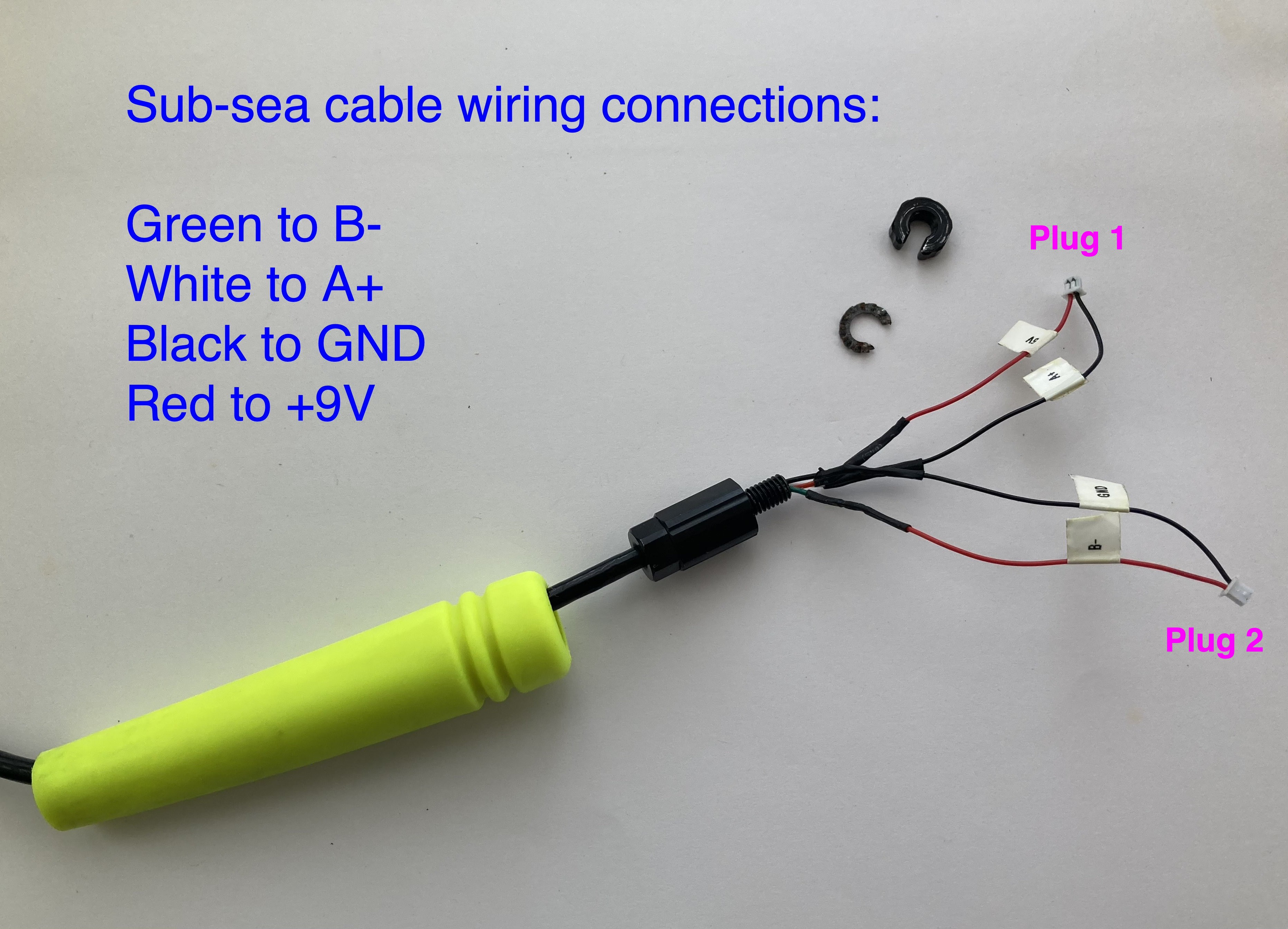
Prepare the float box end of the sub-sea cable by soldering 2 x 2-way Micro JST female connectors to the 4-core cable. Ensure the wire colours correspond to the connections made in Step 5. Plug 1 corresponds to Socket 1 and Plug 2 corresponds to Socket 2.
![]()
-
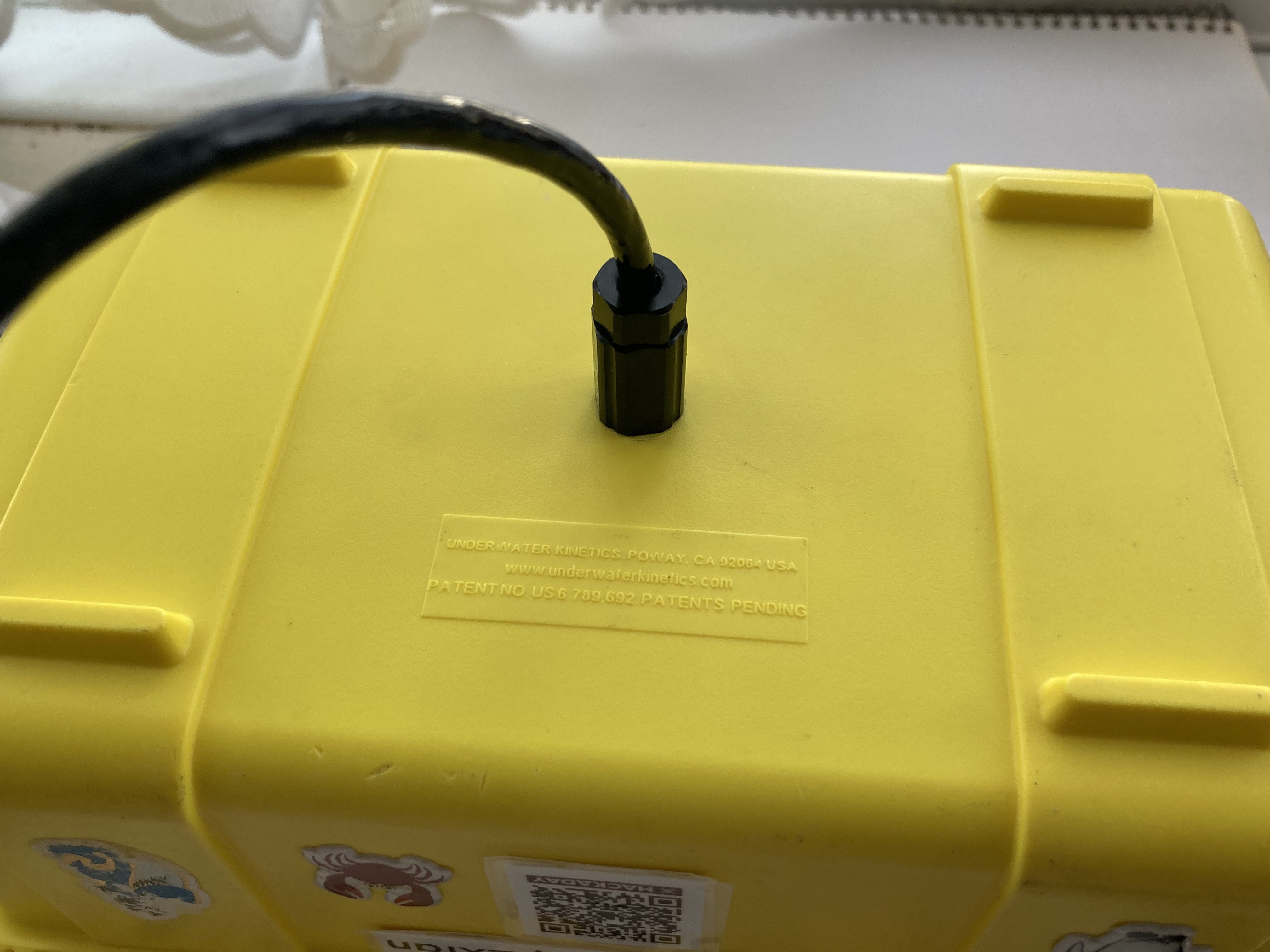
23Step 23: Attach the sub-sea cable to the float box
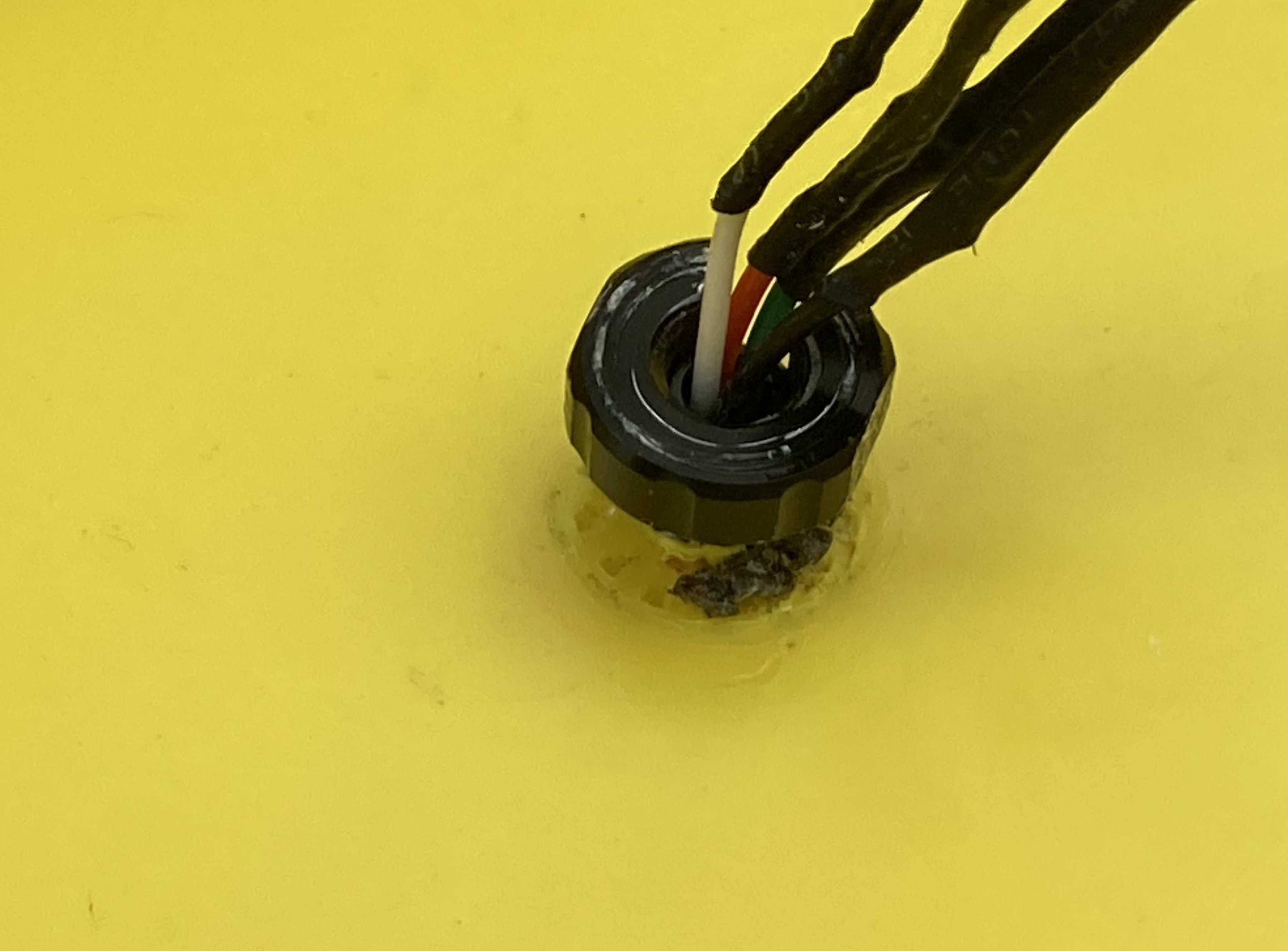
Thread the penetrator through the base of the float box, making sure to take care when passing through the micro JST connectors. Install the shake proof washer and nut using a 12mm spanner/wrench to tighten. Push the rubber boot onto the body of the penetrator for a snug fit against the float box base.
Both washer and nut are split so that they can be threaded over the wiring assembly for easy insertion and removal. The washer is positioned on the inside of the case, underneath the nut.
Internal penetrator fixing
![]()
Installed cable penetrator, inside view
![]()
Installed cable penetrator, outside view
![]()
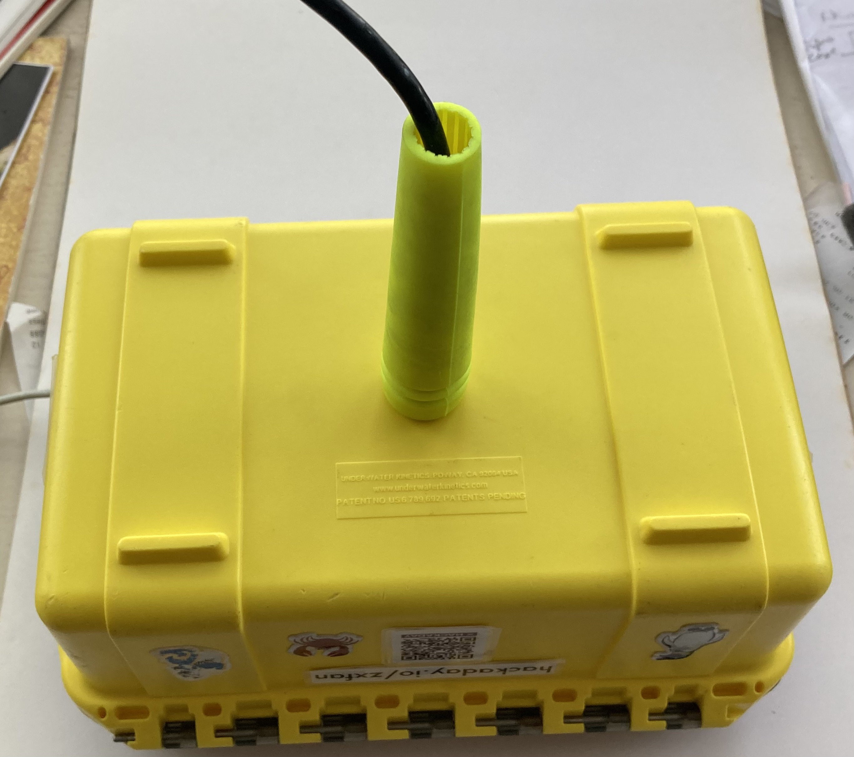
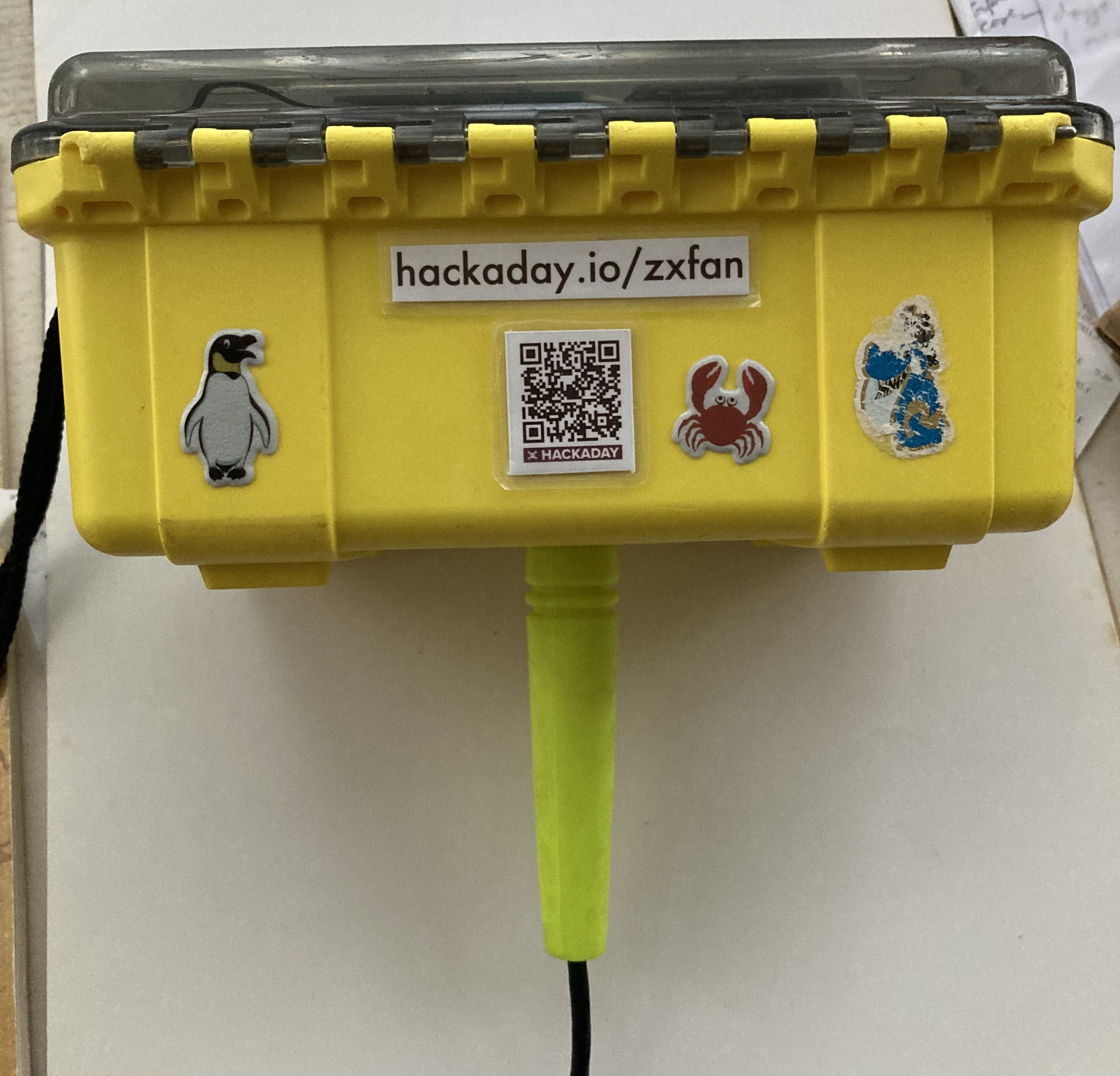
Rubber strain relief installed snug against the box
![]()
-
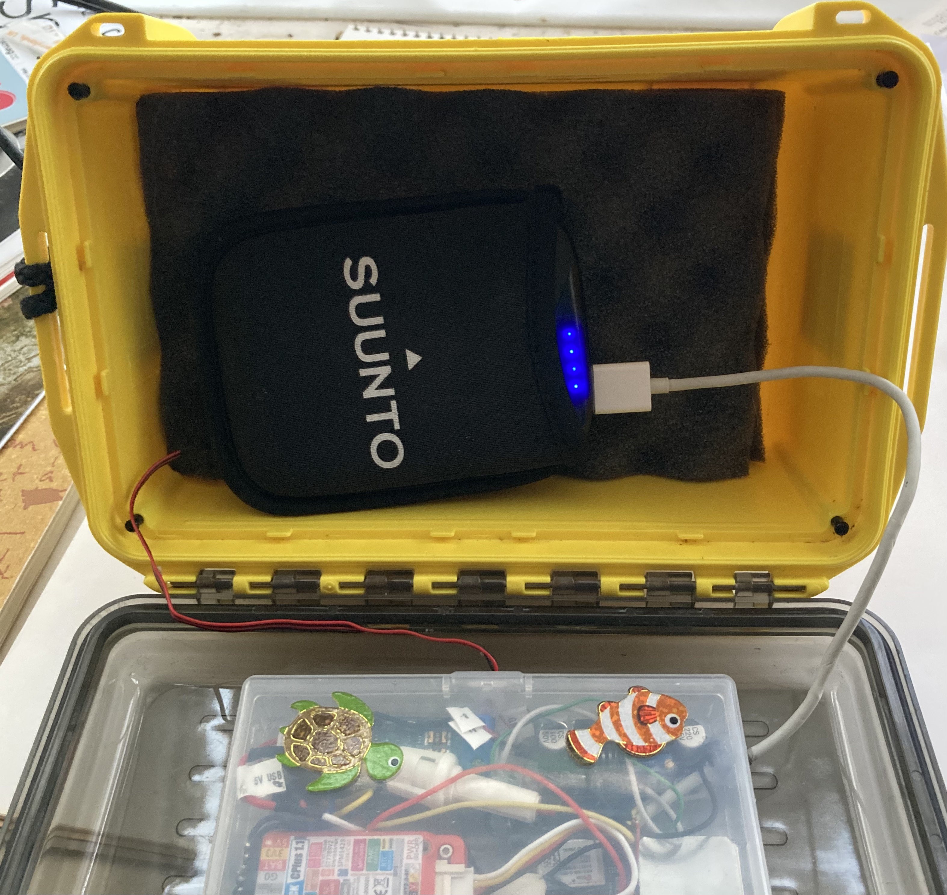
24Step 24: Connect the Lemon enclosure to the sub-sea cable
Connect the 2 x 2-way micro JST connectors, ensuring Socket 1 connects to Plug 1 and Socket 2 connects to Plug 2. Check that the individual wire labels correspond correctly.
Add some foam to the base of the float box and the float is ready to carry your 5V Power Bank and WiFi/4G Hotspot (or mobile phone with hotspot). Add additional foam to pack the box so that the power bank does not move around.
![]()
![]()
![]()
-
25Step 25: Prepare the navigation pod/enclosure end of the sub-sea cable
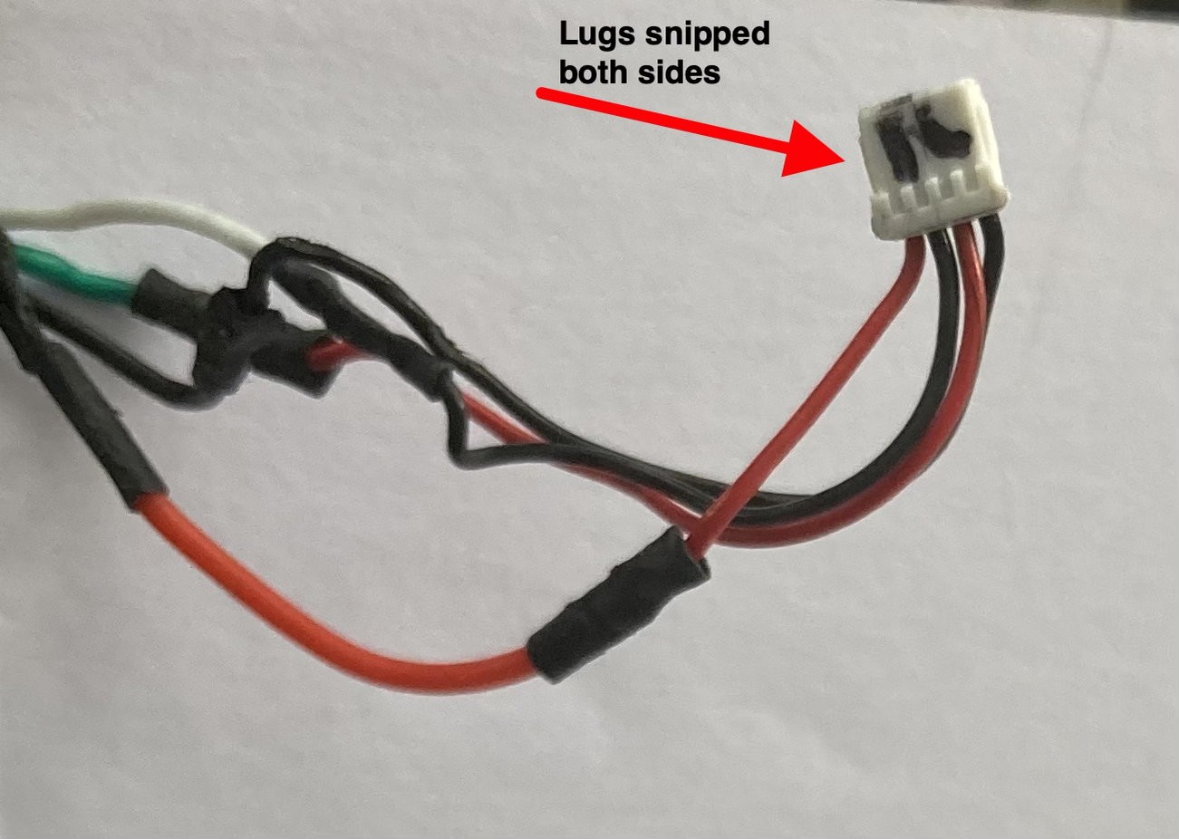
Prepare the navigation pod end of the sub-sea cable by soldering 1 x 4-way Micro JST female connector to the 4-core cable. Carefully snip the lugs off the sides off the 4-way connector so that it can fit through the drill hole for the gopro enclosure. Label the plug 'R'.
(pins counted from left to right)
Subsea wire Red (9V) to pin 1 (the leftmost red wire of plug R)
Subsea wire White (A+) to pin 2 (the next black wire)
Subsea wire Green (B-) to pin 3 (the next red wire)
Subsea wire Black (0V) to pin 4 (the rightmost black wire of plug R)
![]()
-
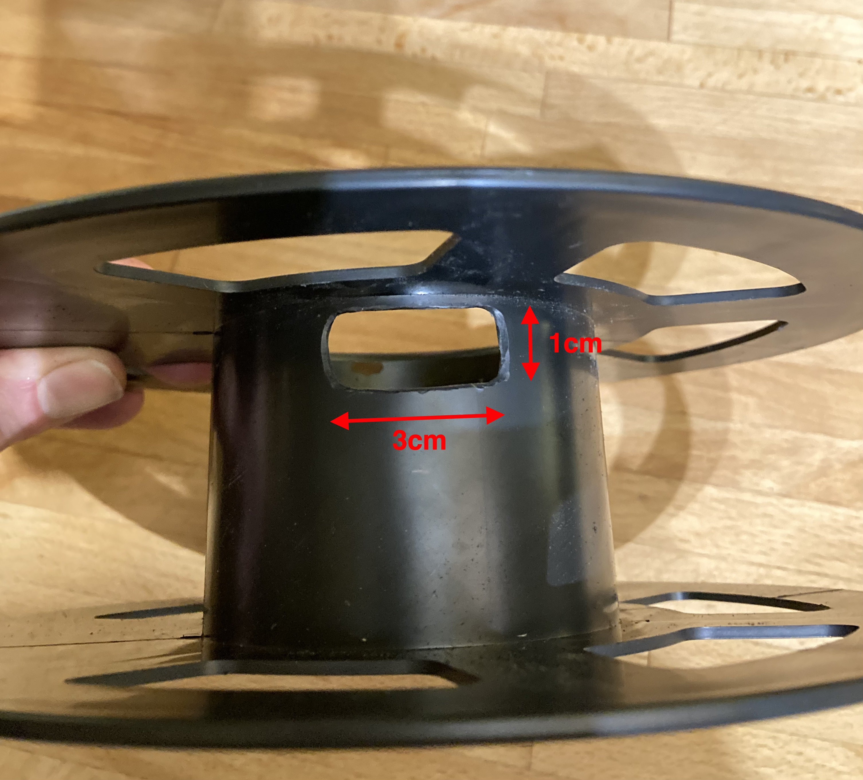
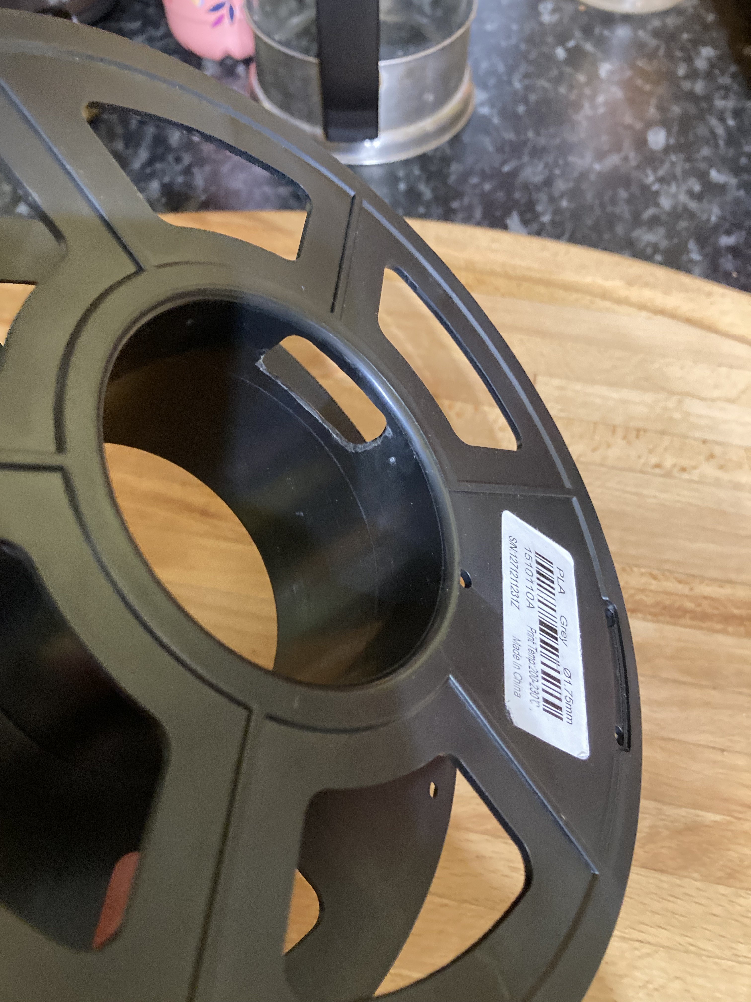
26Step 26: Prepare the spool
Prepare the cable spool by cutting a slot with a rotary tool. approximately 3 cm x 1 cm, to allow the cable to feed through to the navigation pod.
![]()
![]()
-
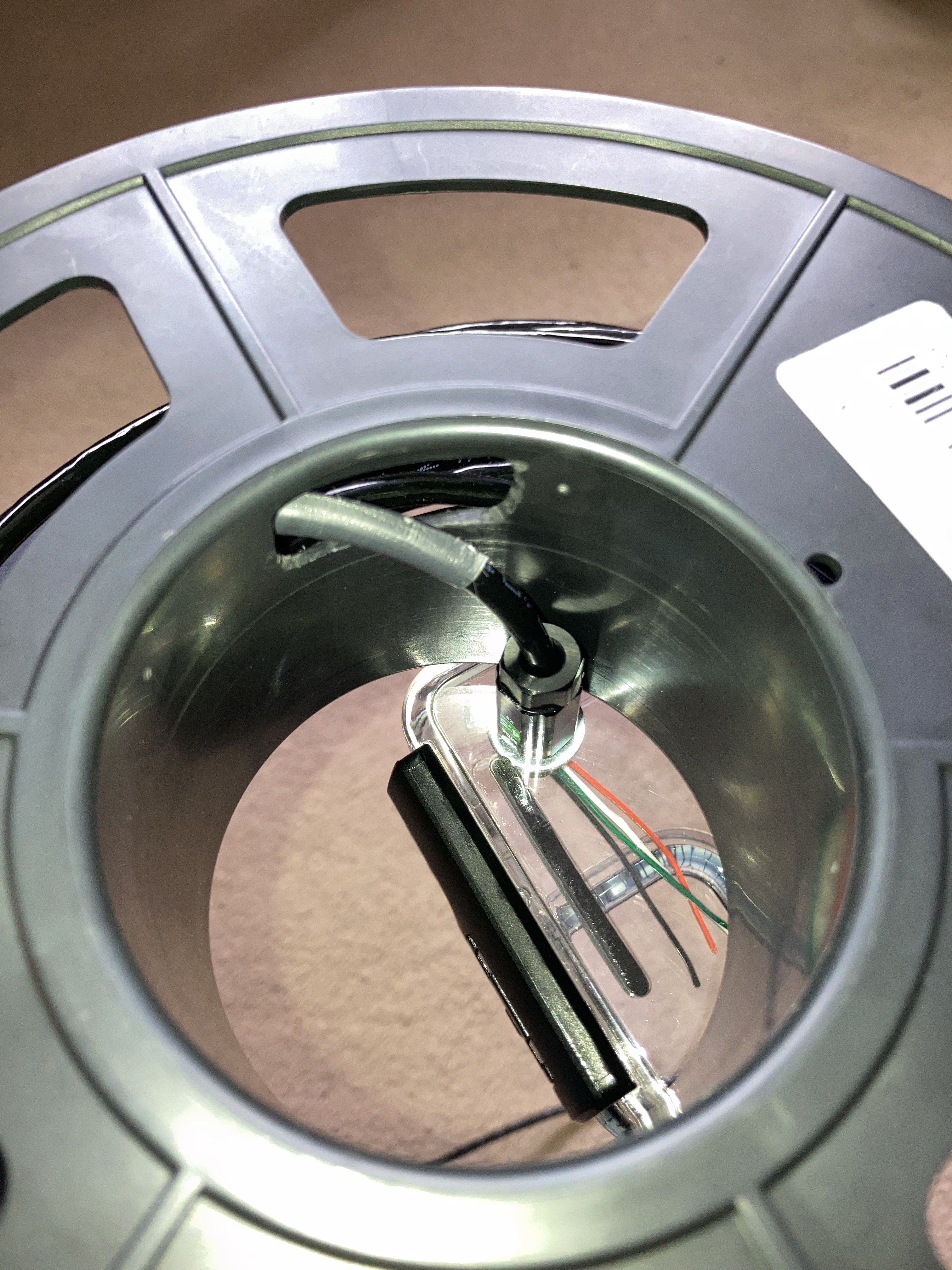
27Step 27: Drill navigation pod for wet link penetrator
Drill a 6mm hole (recommend using a stepped drill bit) at a position 20mm x 20mm from the top and right sides of the door of the enclosure, viewed from the back. Drill from the outside of the enclosure to the inside.
(Photo taken later in the build process, your enclosure will be empty at this stage.)
![]()
-
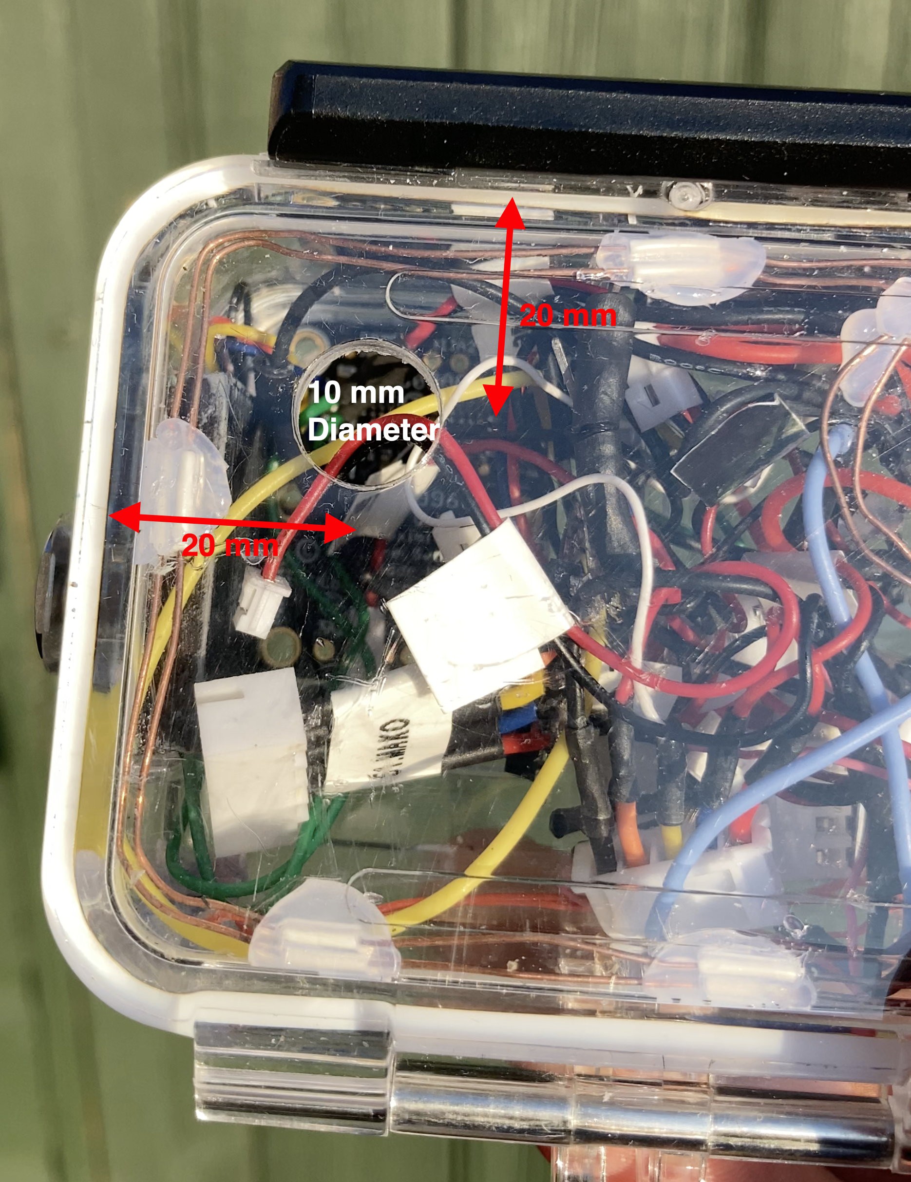
28Step 28: Drill hole for depth sensor
Drill a 10mm hole (recommend using a stepped drill bit) at a position 20mm x 20mm from the top and left sides of the door of the enclosure, viewed from the back.
Drill from the outside of the enclosure to the inside.
(Photo taken later in the build process, your enclosure will be empty at this stage.)
![]()
-
29Step 29: Finalise spool assembly
Thread the penetrator through the spool cut-out and insert the penetrator into the enclosure (offered up to the spool). Mark where the cable passes through the spool cut-out and apply some duct tape to prevent abrasion. The cable penetrator can now be removed.
![]()
Position for navigation pod - will be fixed in place in a later step with 2mm nano tape.
![]()
-
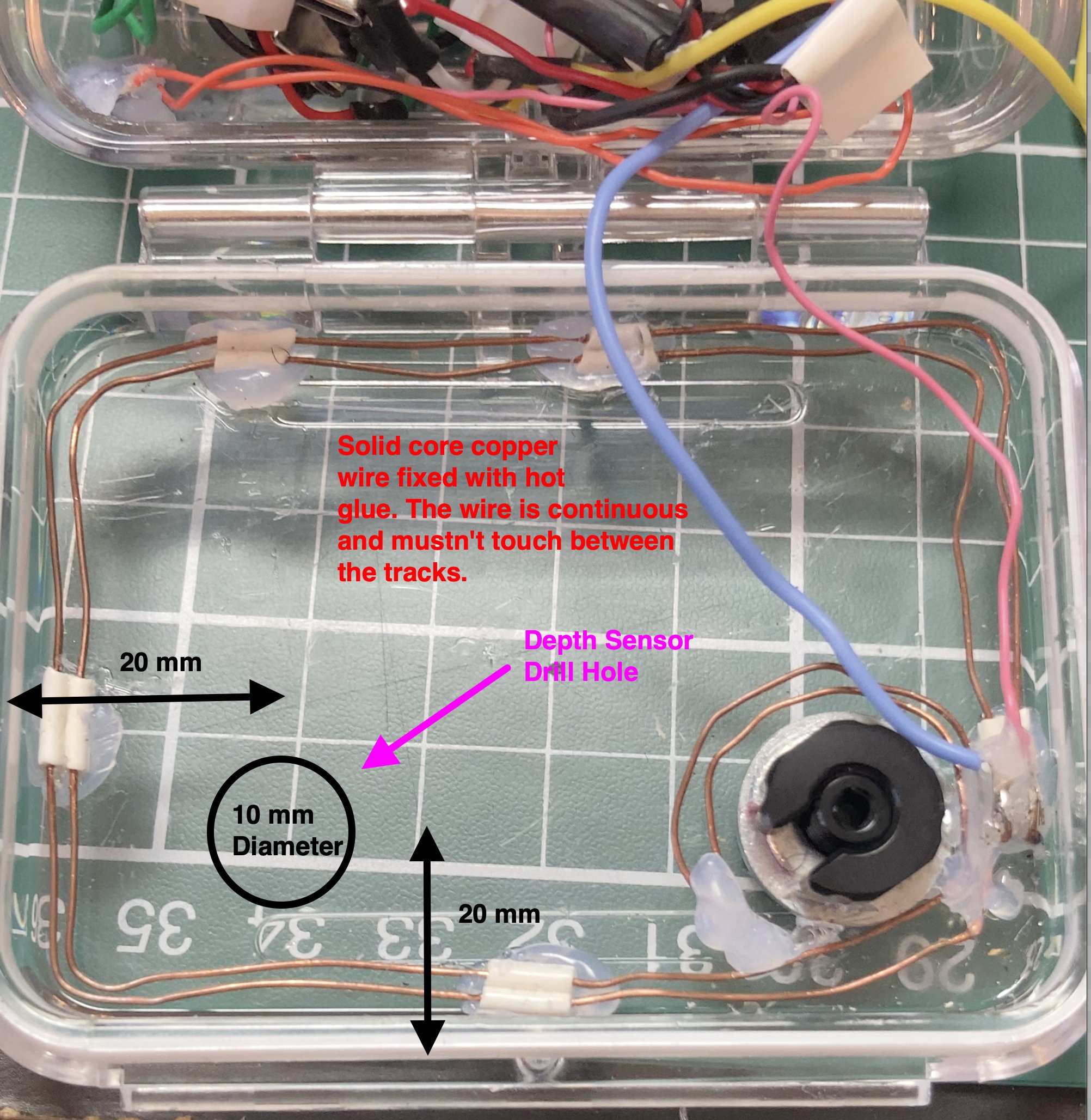
30Step 30: Construct and Mount Leak Detector
Take a length of solid core copper wire (eg speaker wire) and form into a dual track with two flying wires (pink and blue) attached as shown in the photo. The dual tracks must not touch each other. The leak detector works when water shorts across the two tracks. Use hot glue to affix to the inside of the back door of the navigation pod. Disregard the temporary hole stopper that was in place at the time the photo was taken.
![]()
"Mercator Origins": Sat Nav & Telemetry for Divers
Want to map your dive? Want to navigate like a pro? Even if you are vision-impaired, this will empower you to navigate our underwater world.


Discussions
Become a Hackaday.io Member
Create an account to leave a comment. Already have an account? Log In.