 Mark B Jones
-
31Step 31: Insert and Tighten the Depth Sensor
Insert and tighten the depth sensor, remembering to include the O-Ring.
For further manufacturer's guidance see:
https://bluerobotics.com/store/sensors-cameras/sensors/bar30-sensor-r1/![]()
-
32Step 32: Solder Stemma QT connector to Depth Sensor wires
Solder wires as follows:
Green Sensor Wire I2C SCL --> Yellow Stemma QT Wire
White Sensor Wire I2C SDA --> Blue Stemma QT Wire
Black Sensor Wire GND --> Black Stemma QT Wire
Red Sensor Wire 2.5V to 5V --> Red Stemma QT Wire
![]()
-
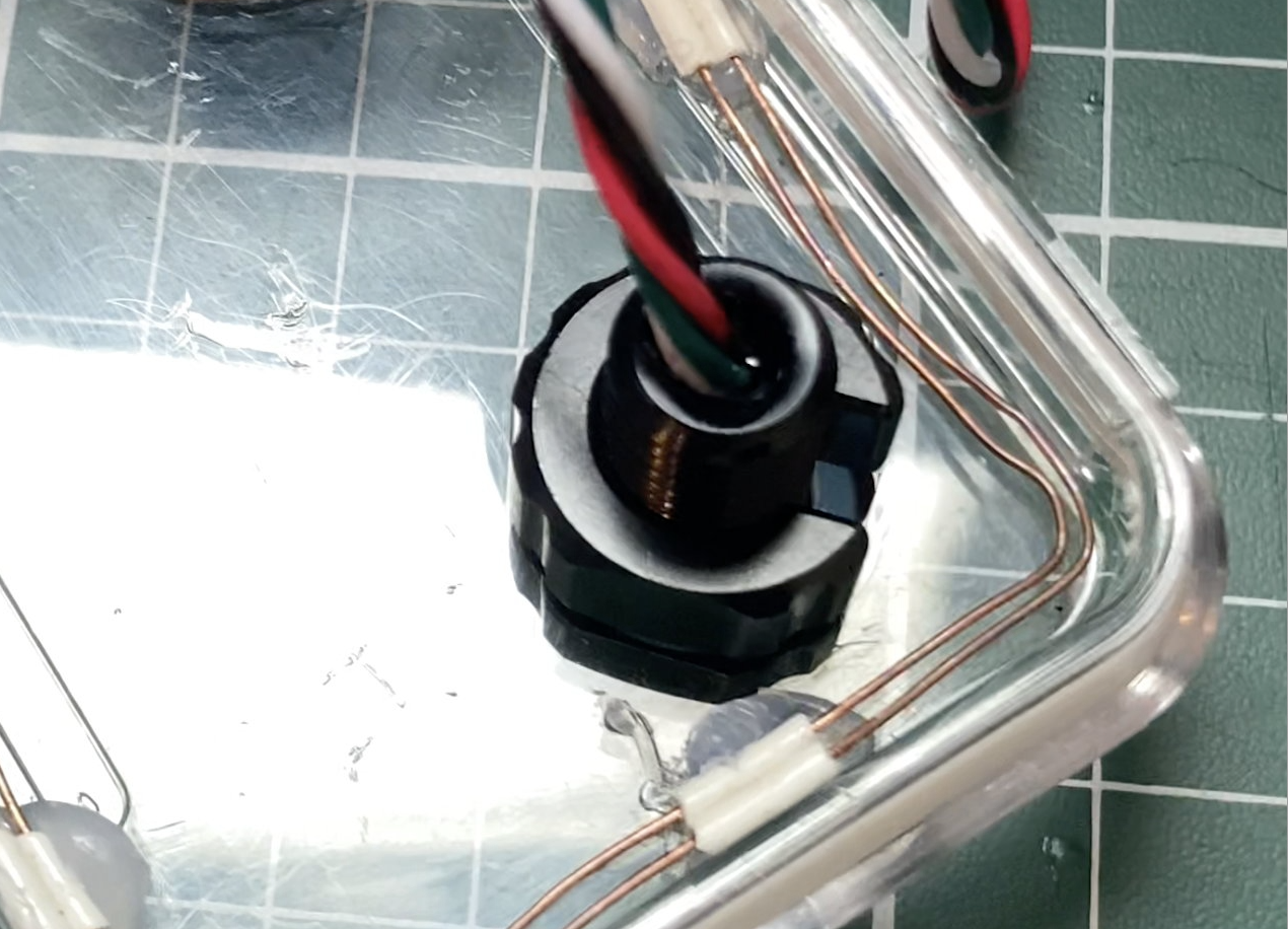
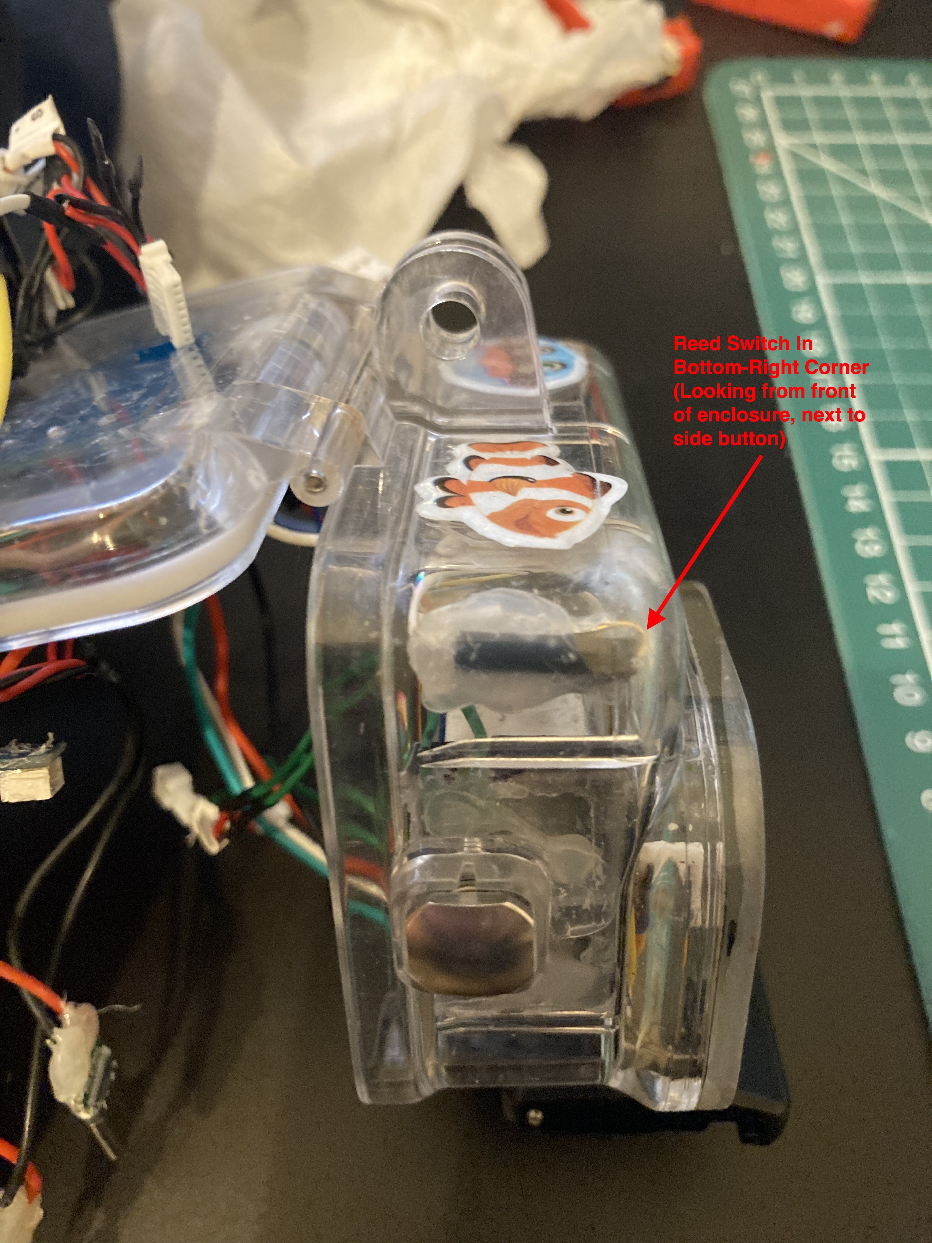
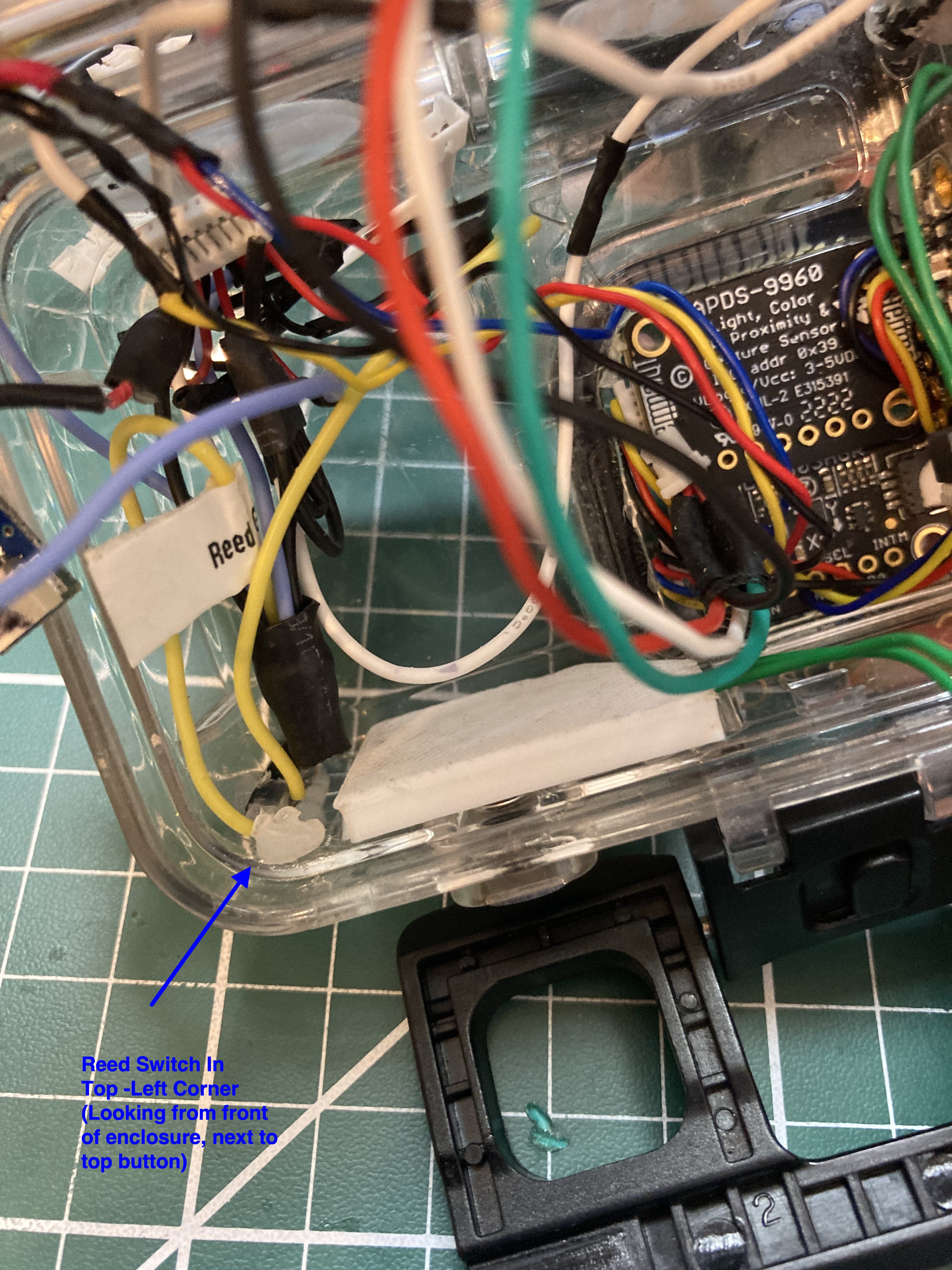
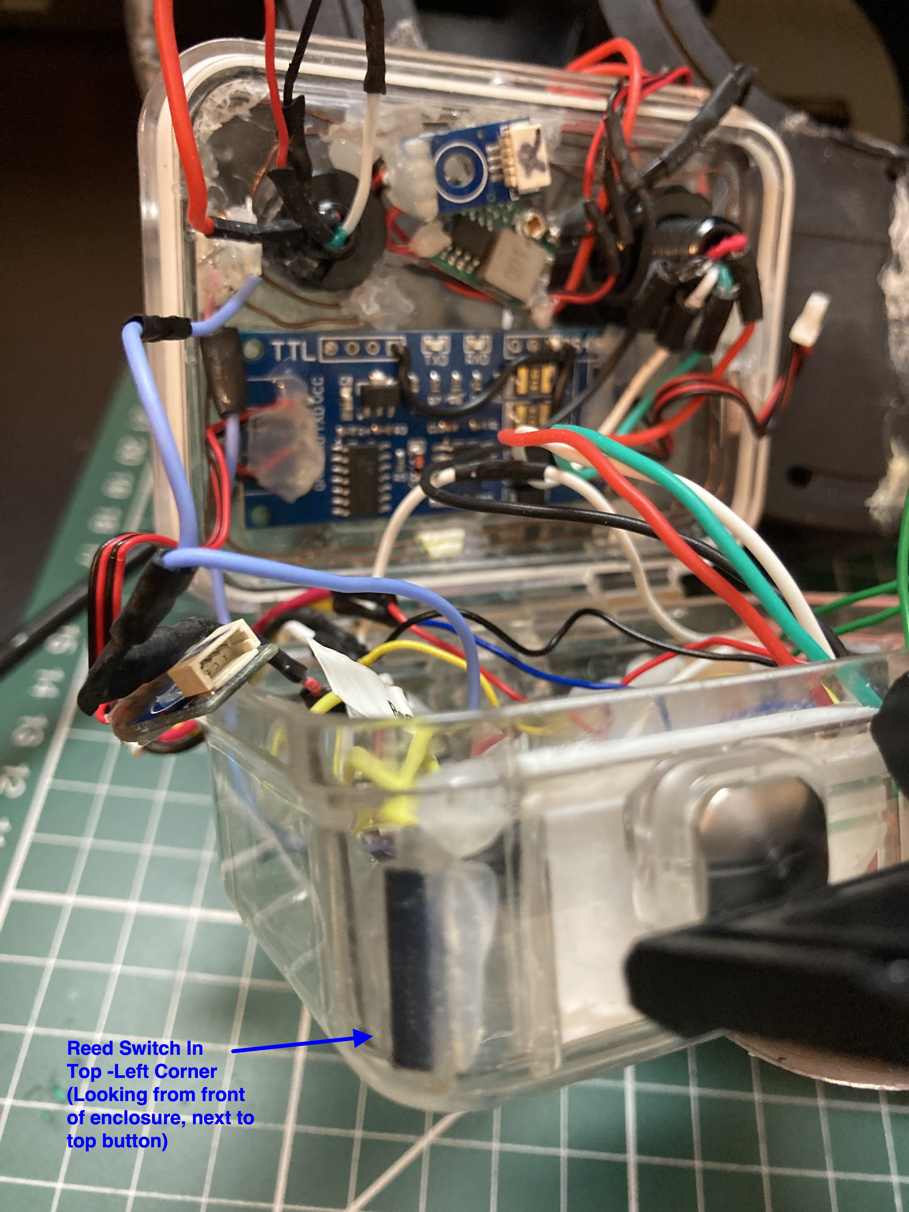
33Step 33: Hot Glue Reed Switches in place
Solder flying leads to each reed switch and glue in position as per photo.
Mount Reed switch in bottom-right corner by side button
![]()
![]()
Mount Reed switch in top-left corner by top button
![]()
![]()
-
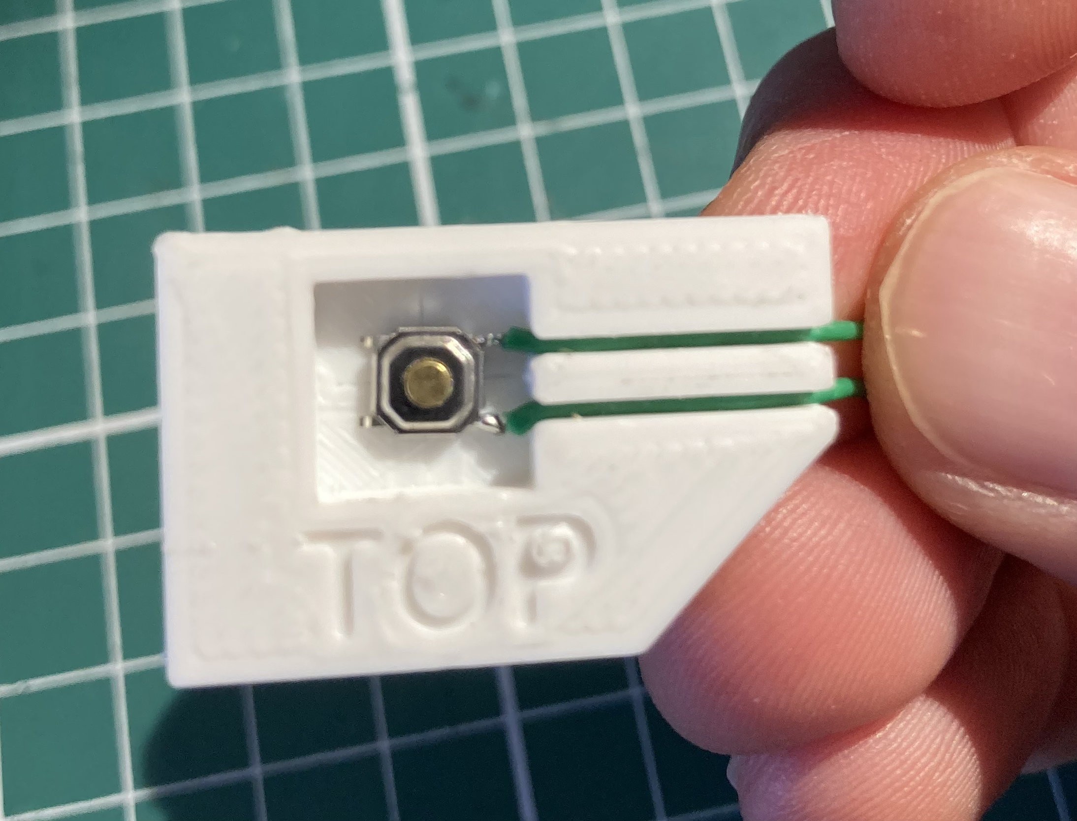
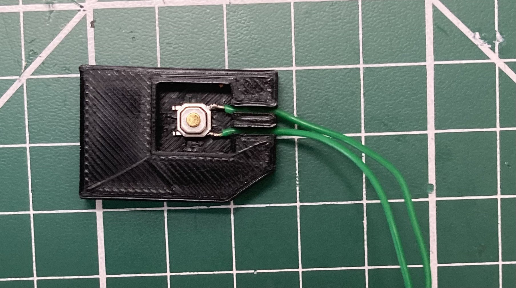
34Step 34: Make Button Mounts
3D Print or make by hand (see button mount schematics) the two button mounts for the navigation pod. Solder wires to the push-to-make microswitches and position in centre of the well at the centre of each mount. Wires should be tight in the channels so that the switch will not move, if loose then glue the switch in place. Solder 2-way Micro JST female connectors to the ends of the wires for each button mount.
Top button mount
![]()
Side button mount
![]()
-
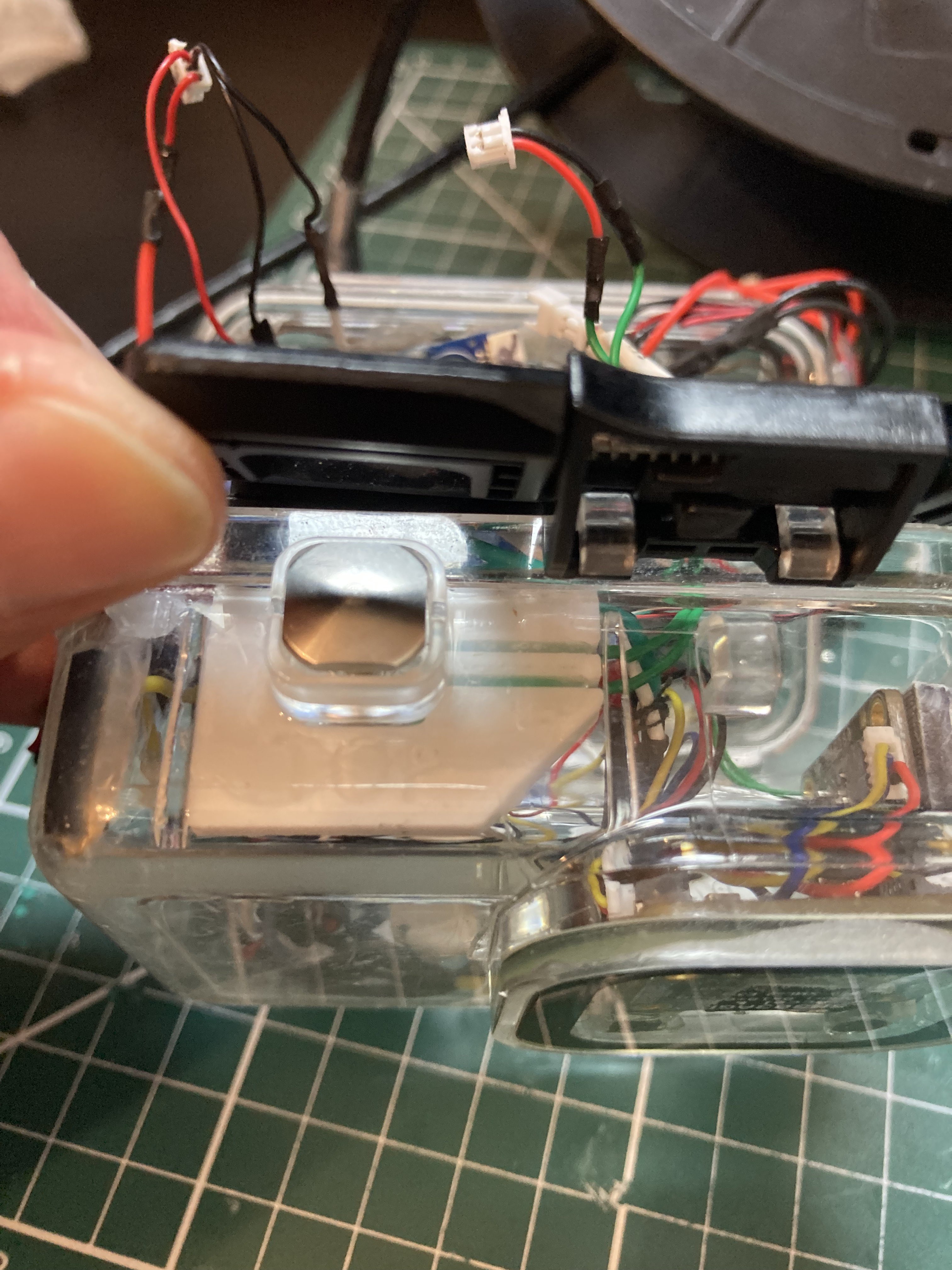
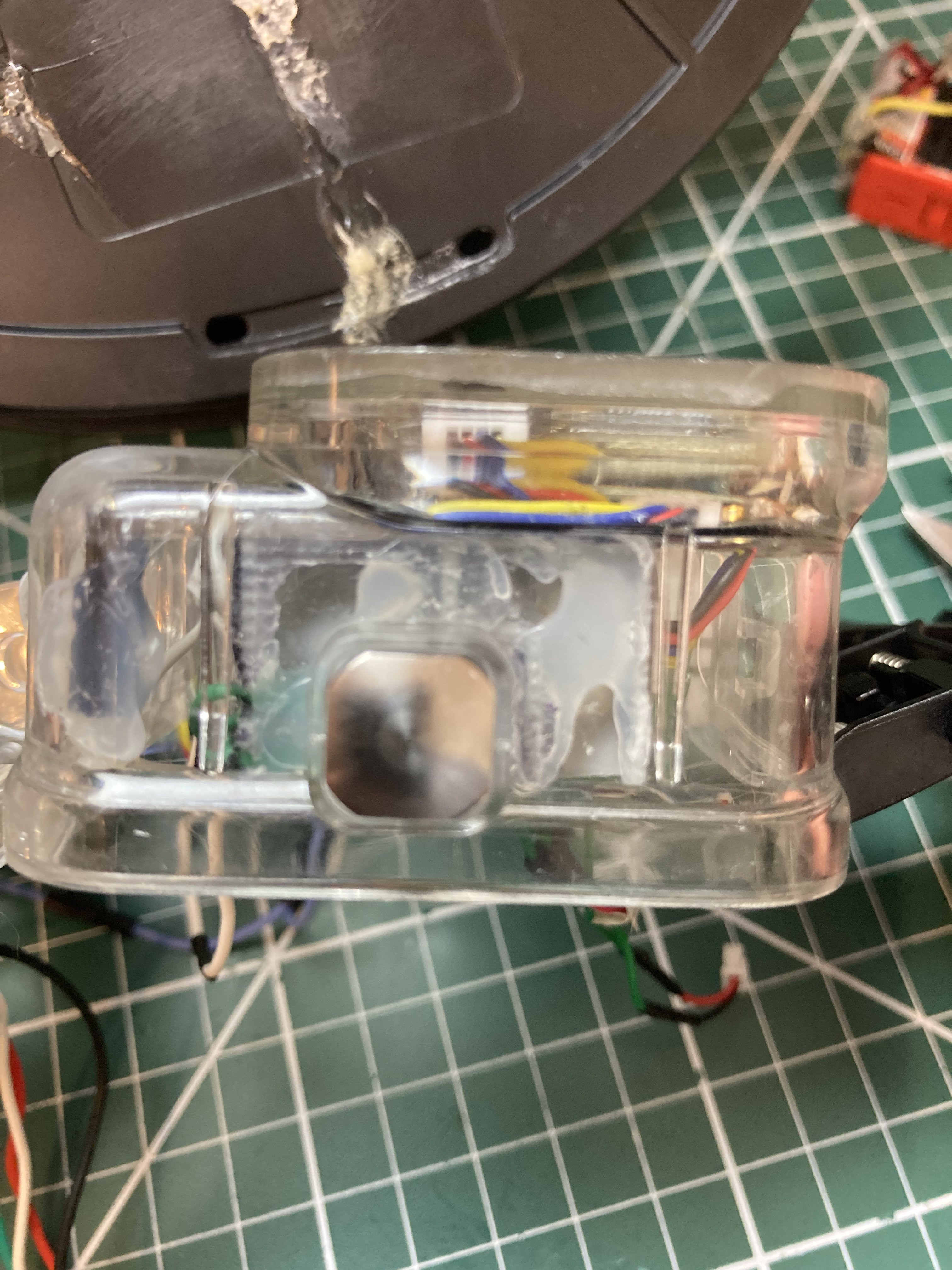
35Step 35: Hot glue the button mounts inside the enclosure
Before gluing, ensure the microswitch is correctly positioned for each mount by offering up to the underside of the physical button. When gluing there is a brief period when the mount position can be adjusted slightly. This should not be necessary as the mount will only just fit between the enclosure mouldings. The top of the mount needs to be inline with the indentation where the case back closes.
Top Button Mount
![]()
Side Button Mount (mount shown has cut away section to show inside)
![]()
![]()
-
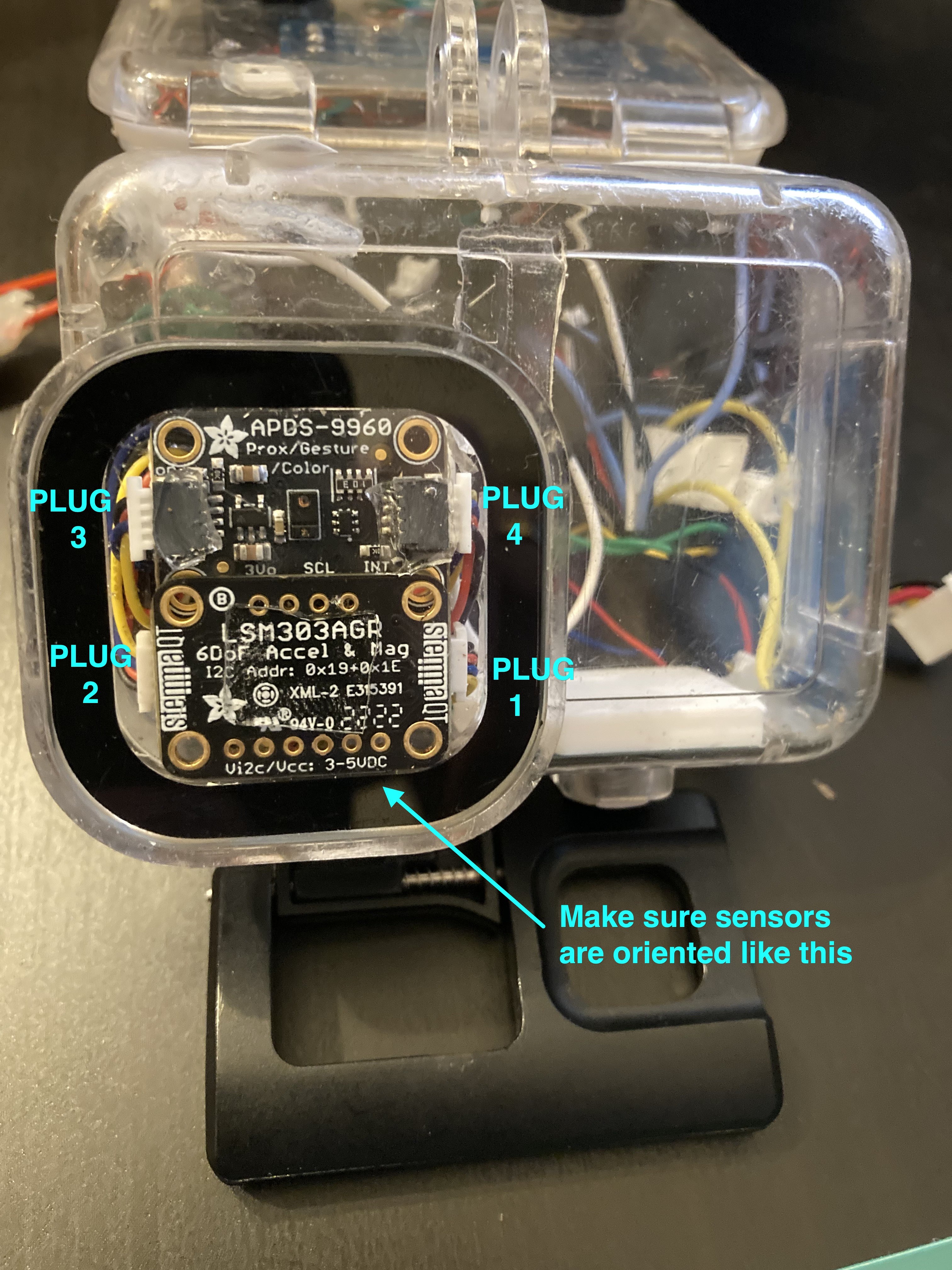
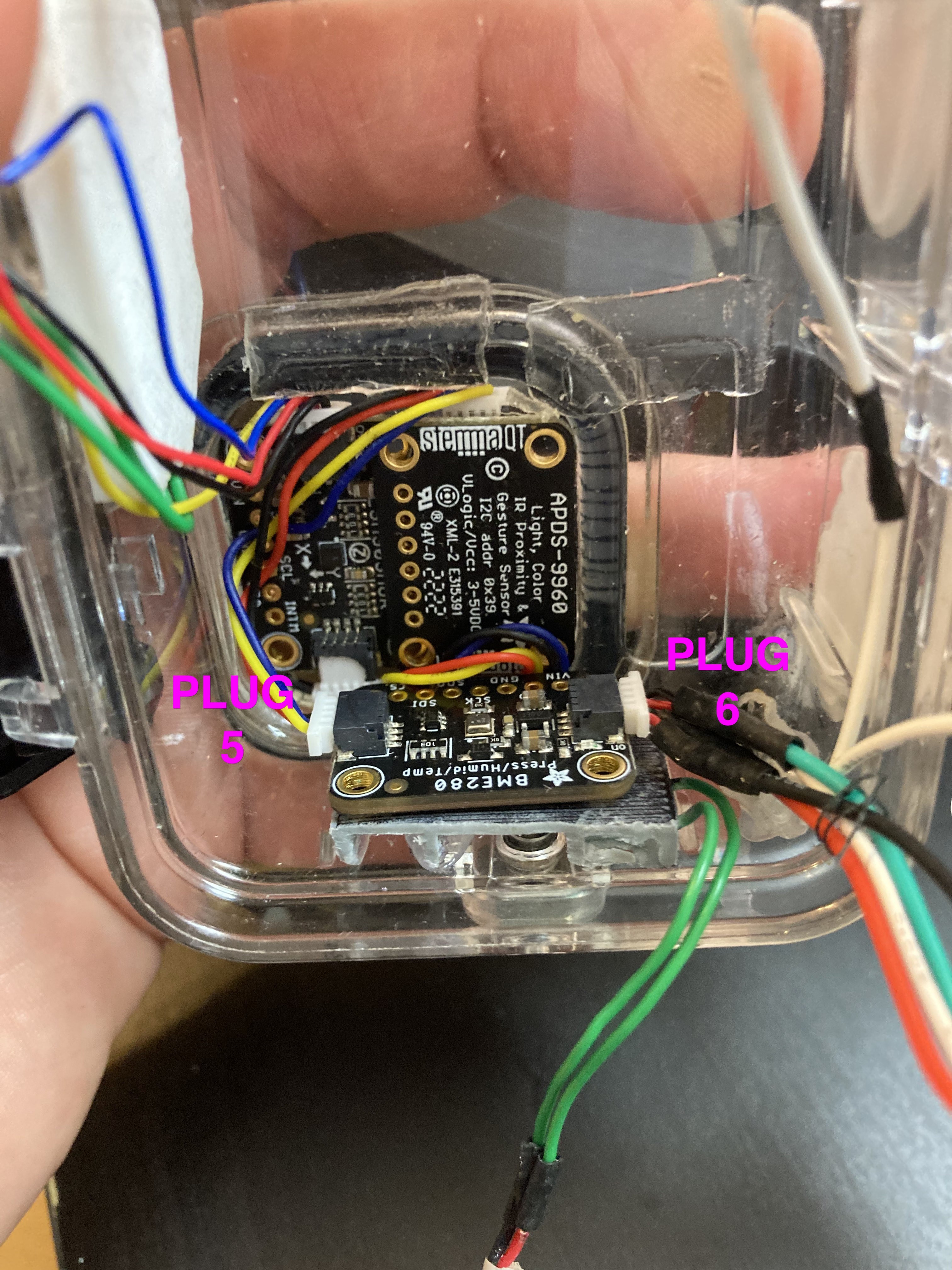
36Step 36: Mount the I2C sensors
All mounting uses 1 mm nano tape. Orientate the sensors as per the photos.
Before mounting note the order with which to connect the sensors with Stemma QT plugs.
Plug 1 attaches to a 4-way cable with a Grove connector at the other end.
Plug 2 connects to Plug 3 via a Stemma QT 4-way cable.
Plug 4 connects to Plug 5 via a Stemma QT 4-way cable.
Plug 6 connects to the Depth Sensor 4-way cable that terminates without a connector on the back of the depth sensor. This plug was attached to the Depth Sensor in Step 32.
* Mount the LSM303AGR Accelerometer/Magnetometer Sensor with PCB Stemma QT sockets facing up into the lens well of the enclosure.
* Mount the APDS-9960 Gesture Sensor next to the Magnetometer but with the Stemma QT sockets downmost. This will expose the sensor to the outside of the enclosure.
* Mount the BME280 Temperature/Humidity/Air Pressure sensor on top of the Side Button.
![]()
![]()
-
37Step 37 – Solder connectors to the RS485 Module and mount module inside the enclosure
First, remove any sockets that are present on the RS485 Module as we need as much free space as possible. Solder a black wire between TTL Ground and RS485 Earth.
Solder 4-core cable to the left (TTL signals) side of the module and at the opposite end solder a 4-way micro JST male connector. Make note of the wire colour coding for your cable, pins are VCC (5V), TXD, TXD and GND. This is the UART male connector, label it ‘U’.
Solder 3-core cable to the right side (RS485 signals) of the module and at the opposite end solder a 4-way micro JST male connector. Make note of the wire colour coding for your cable, pins are GND, B+ and B-. There is no fourth pin. Label the connector ‘B’.
Mount the RS485 Module with hot glue in the lower left of the rear lid of the enclosure. Be careful to position within the leak detector tracks and not on top of them. Use hot glue on top of the solder joints on each side of the module for mechanical strength.
Also in the photo is shown: Plug R which is connected to the sub-sea cable and Socket R which is dealt with in the next step. The Step Down voltage regulator is also shown.
![]()
-
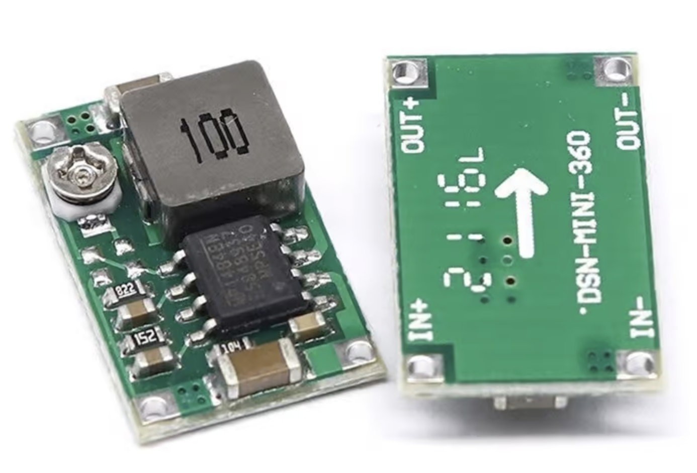
38Step 38 – 5V Step Down Regulator, Socket R and Socket/Plug B
Important: make sure the step down regulator is adjusted using its potentiometer to output 5V from the 9V source before connecting the output to the rest of the enclosure electronics. The output is configurable above 5V and if this happens this will damage or destroy the rest of the enclosure electronics.
The suggested plug/sockets used and their pins are discretionary and can be modified as long as the schematic is adhered to.
Mount the Step Down converter above the RS485 module using 1mm nano tape.
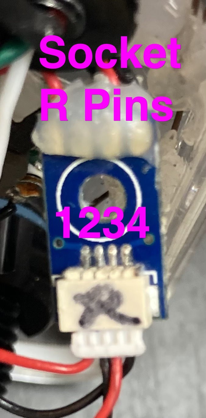
Socket R and Socket B are both 4-way male Micro JST connectors. See Step 25 for Plug R pin allocations.
Plug R mates to Socket R, which connects to:
Socket R Pin 1 --> IN- (0V)
Socket R Pin 2 --> wire to Socket B Pin 2 (carries RS485 A+ signal)
Socket R Pin 3 --> wire to Socket B Pin 3 (carries RS485 B- signal)
Socket R Pin 4 --> IN+ (9V)
Step Down Regulator OUT+ --> 5V supply for the system (see schematic)
Step Down Regulator OUT- --> 0V ground for the system (see schematic)
Socket B (same pin order as socket R) mates with Plug B, has connections:
Socket B Pin 1 not connected
Socket B Pin 2 --> Plug B Pin 2 --> RS485 Module A+
Socket B Pin 3 --> Plug B Pin 3 --> RS485 Module B-
Socket B Pin 4 (0V) --> Plug B Pin 4 --> RS485 Module Ground
Plug U mates to socket U - same pin order as socket R - (TTL input to RS485):
Plug U Pin 1 --> 5V (from step down regulator OUT+)
Plug U Pin 2 --> TX from Mako M5 Stick C Plus HAT phototransistor
Plug U Pin 3 --> RX to Mako M5 Stick C Plus HAT
Plug U Pin 4 --> Ground
![]()
![]()
-
39Step 39 – Solder 8-way connectors to 8-way 90-degree headers for M5 Stick C Plus 'Tiger'
The 8-way HAT for the M5 Stick C Plus ‘Tiger’ requires an 8-way Micro JST male socket and an 8-way 90-degree header to be soldered together. Hot glue has been used to mechanically reinforce the solder joints at the header end. All pins have straight through connections. Velcro is applied to the back of the stick to allow for easier removal from the enclosure.
![]()
![]()
![]()
-
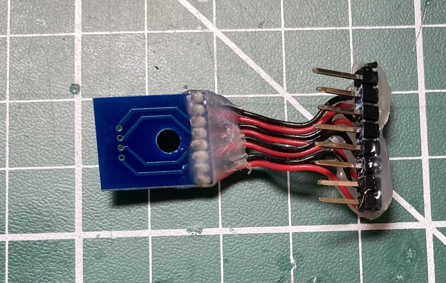
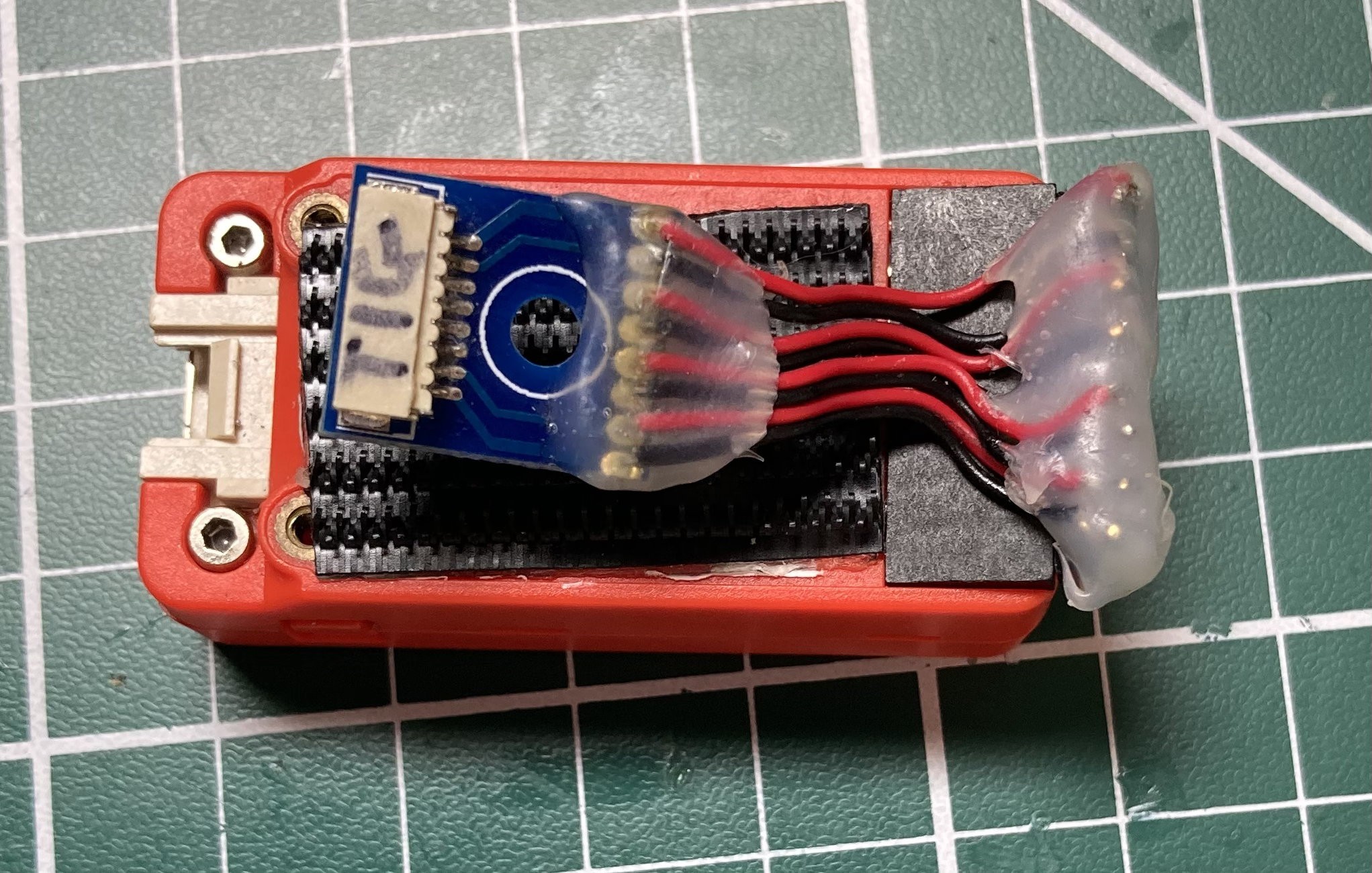
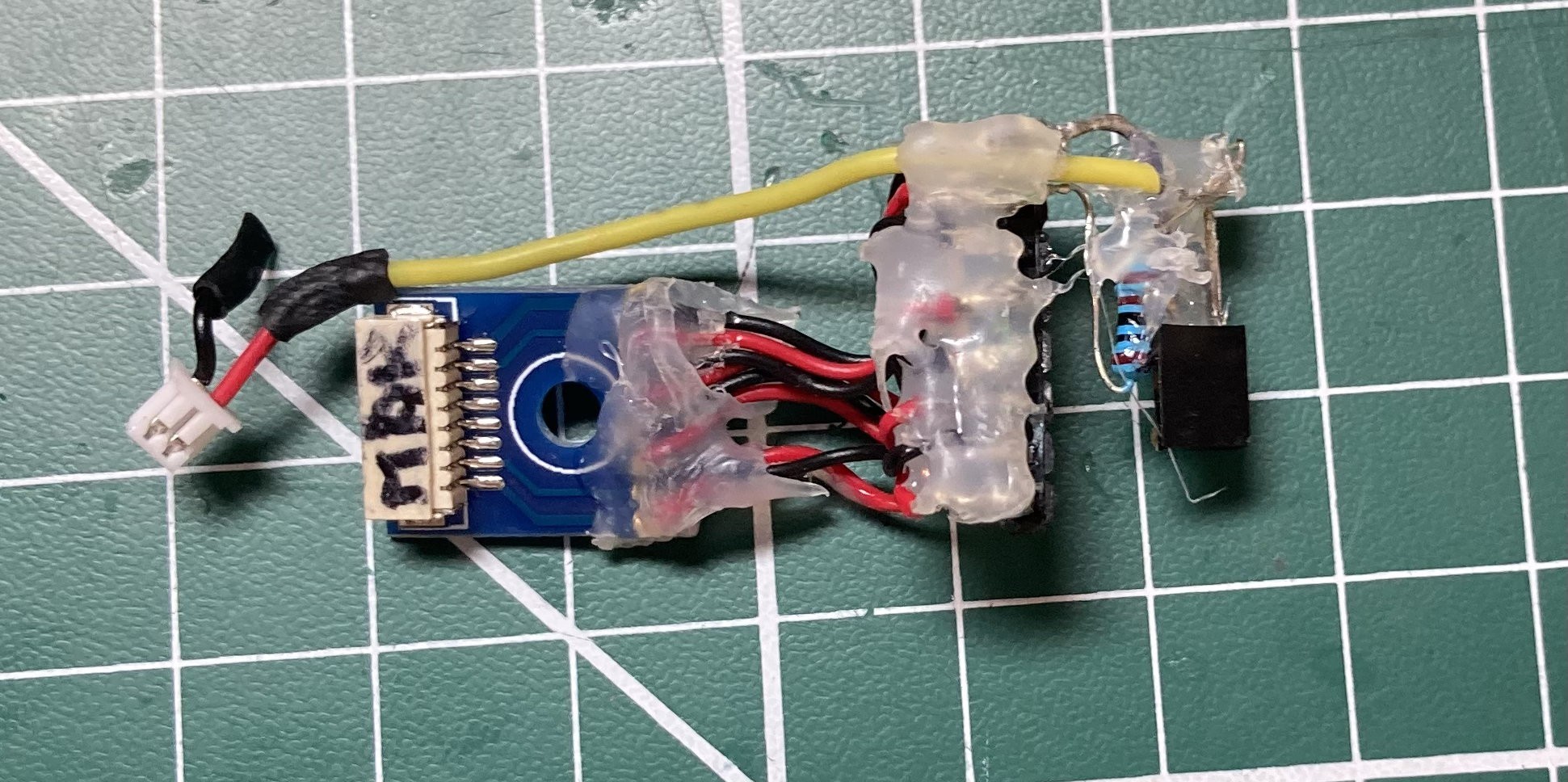
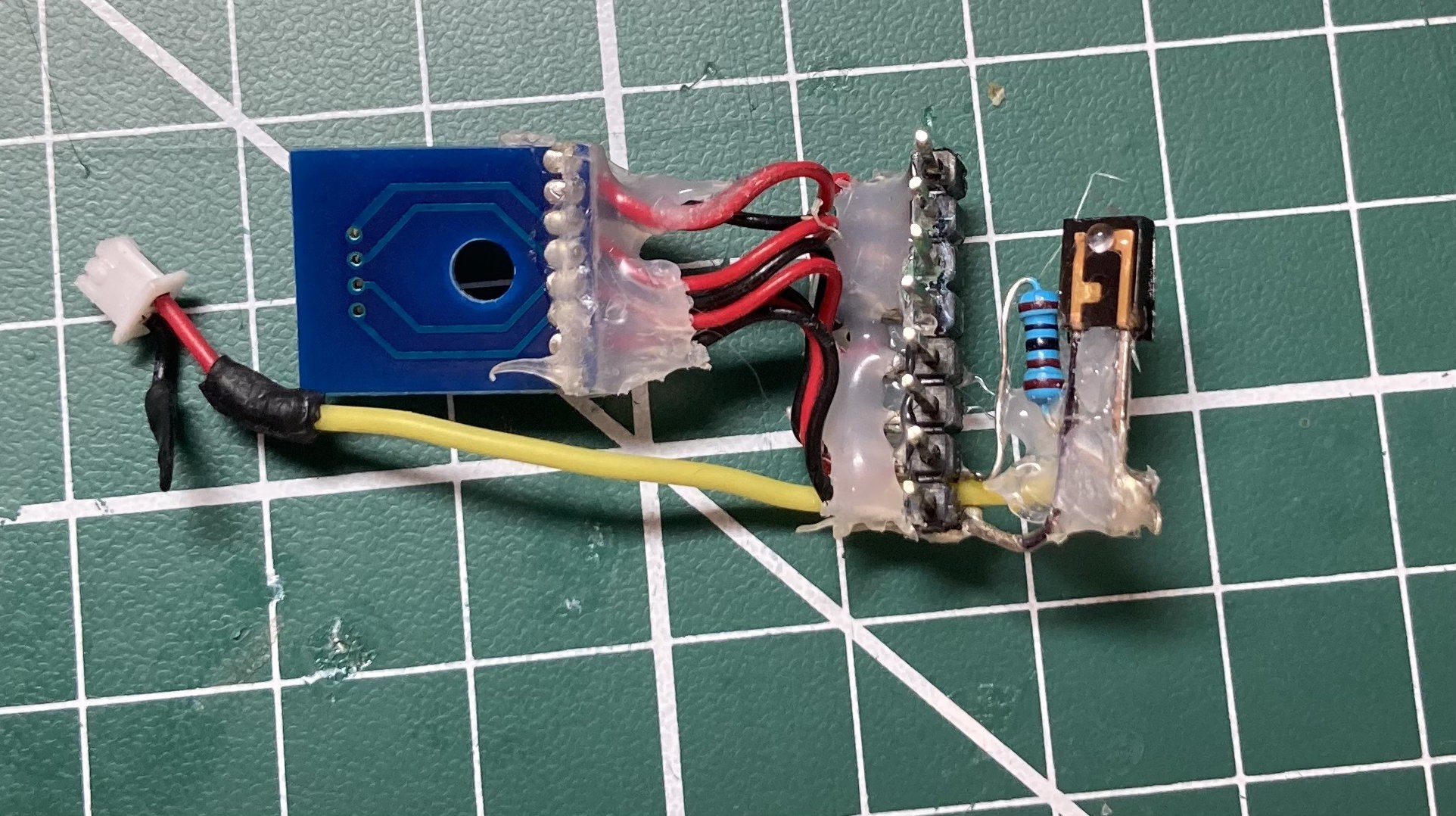
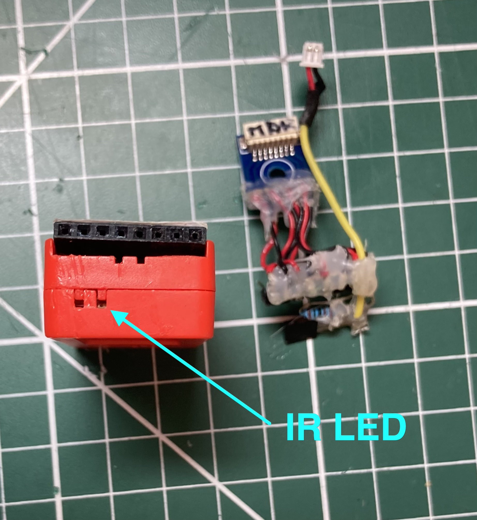
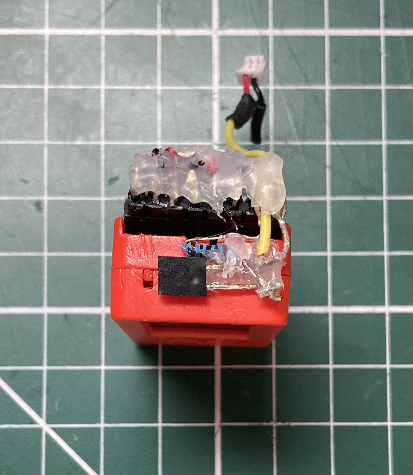
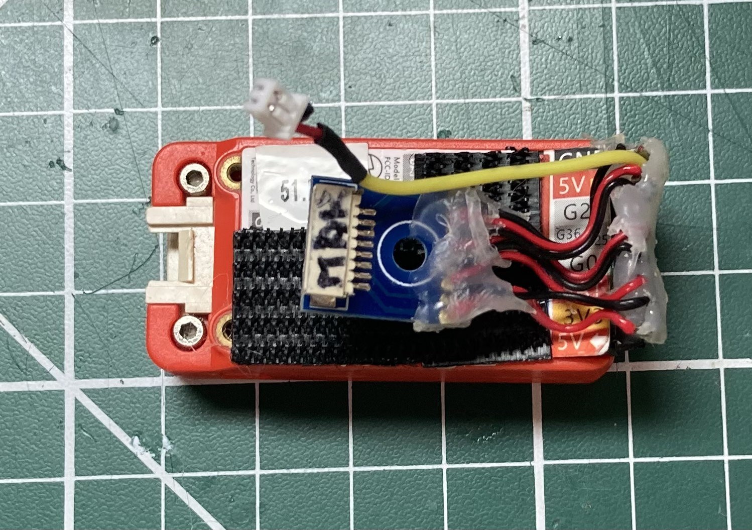
40Step 40 - Solder 8-way connectors to 8-way 90-degree headers and phototransistor/resistor for M5 Stick C Plus 'Mako'
The 8-way HAT for the M5 Stick C Plus ‘Mako’ requires an 8-way Micro JST male socket and an 8-way 90-degree header to be soldered together. All pins have straight through connections. There is also a resistor and phototransistor that needs to be connected to HAT 5V and GND pins as per the schematic. A flying lead (yellow in photo) is soldered at the junction between the resistor and the phototransistor as per the schematic – this is the TX signal from the ‘Mako’ Stick. A 2-way Micro JST plug is used to terminate this lead (only one pin is used).
Hot glue has been used to mechanically reinforce the solder joints at the header end. All pins have straight through connections. Velcro is applied to the back of the stick to allow for easier removal from the enclosure.
Apply black insulation tape to the back of the phototransistor so transient light (bright sunlight) does not interfere with operation. The phototransistor sensor area must be positioned over the M5 Stick Infra Red LED emitter hole in the M5 Stick case.
![]()
![]()
![]()
![]()
![]()
"Mercator Origins": Sat Nav & Telemetry for Divers
Want to map your dive? Want to navigate like a pro? Even if you are vision-impaired, this will empower you to navigate our underwater world.


Discussions
Become a Hackaday.io Member
Create an account to leave a comment. Already have an account? Log In.