 Mark B Jones
-
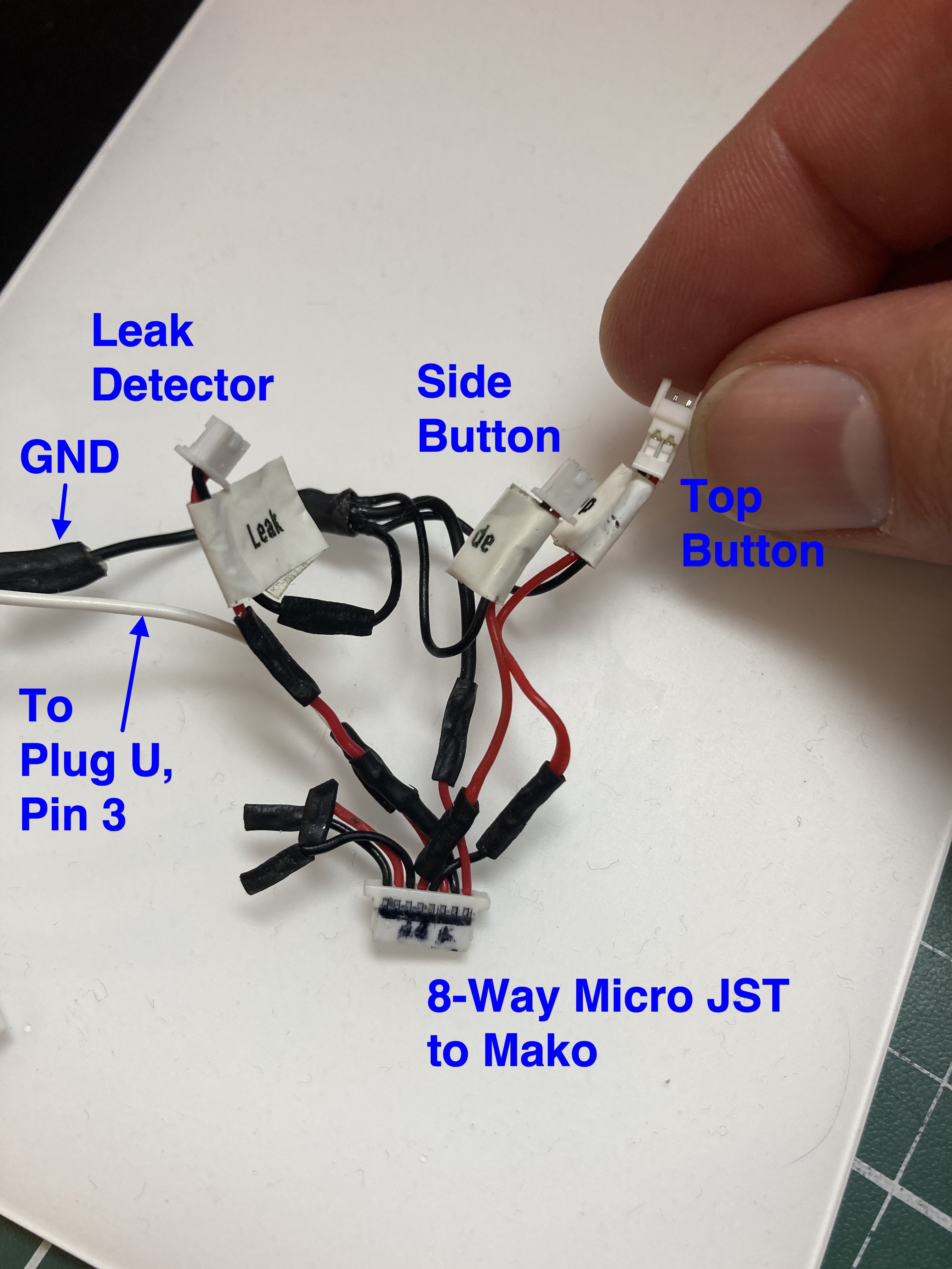
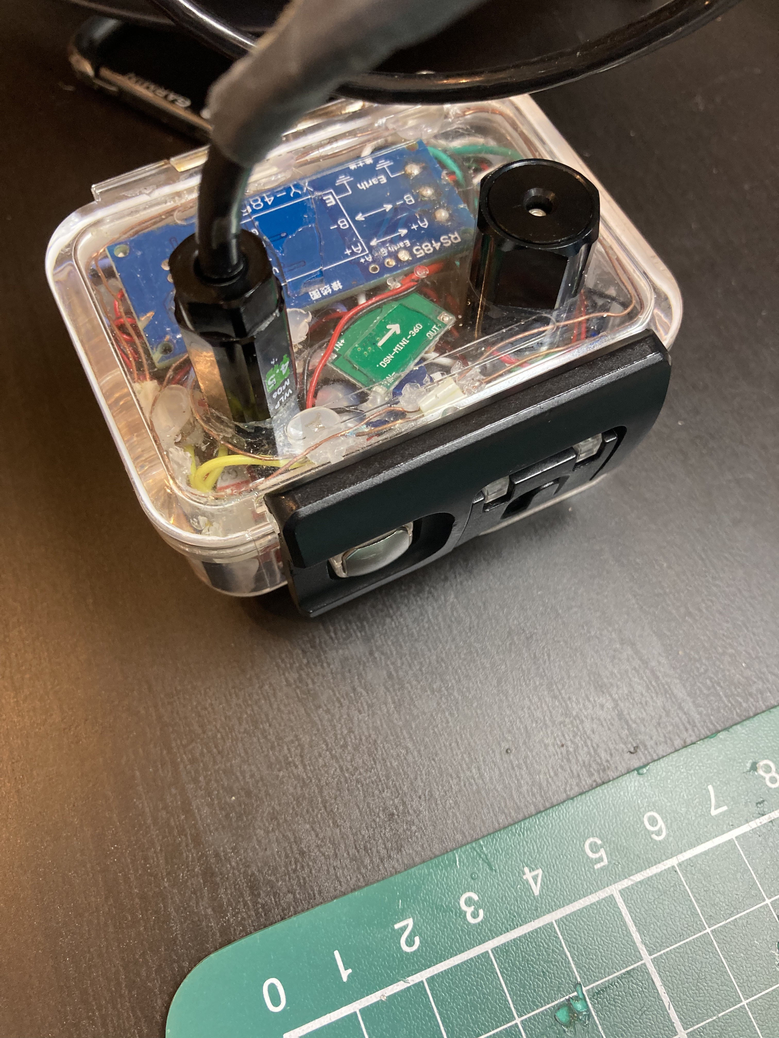
41Step 41: Prepare Mako M5 Stick C Plus 8-way Micro JST female plug
Refer to the schematic for connections to the Mako Stick’s 8-way HAT. The example shown in the photo provides 2-way micro JST plugs/sockets for the Side Button, the Top Button and the Leak Detector. The black wire on the left is Ground, the white wire connects to pin 3 of Plug U.
![]()
-
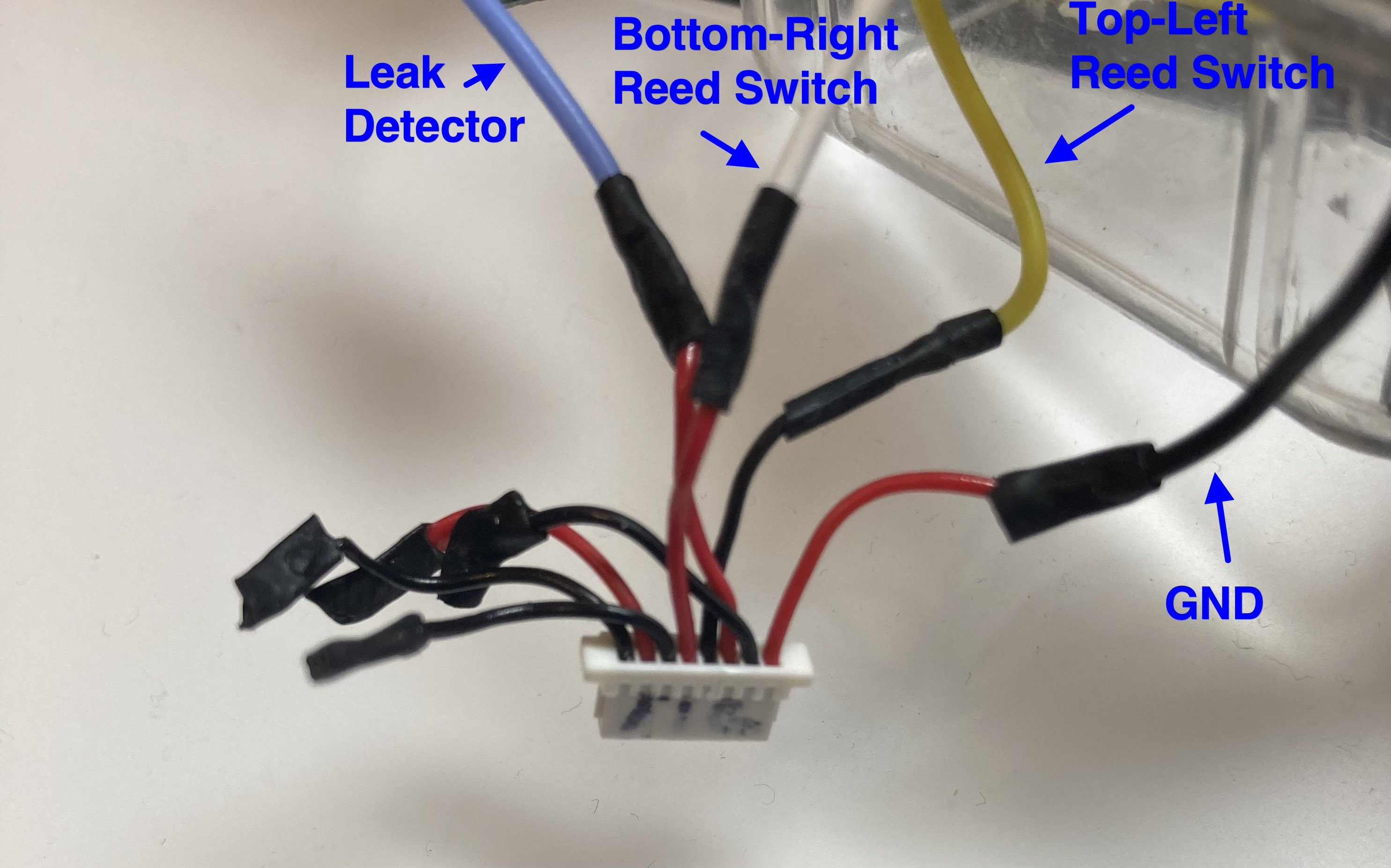
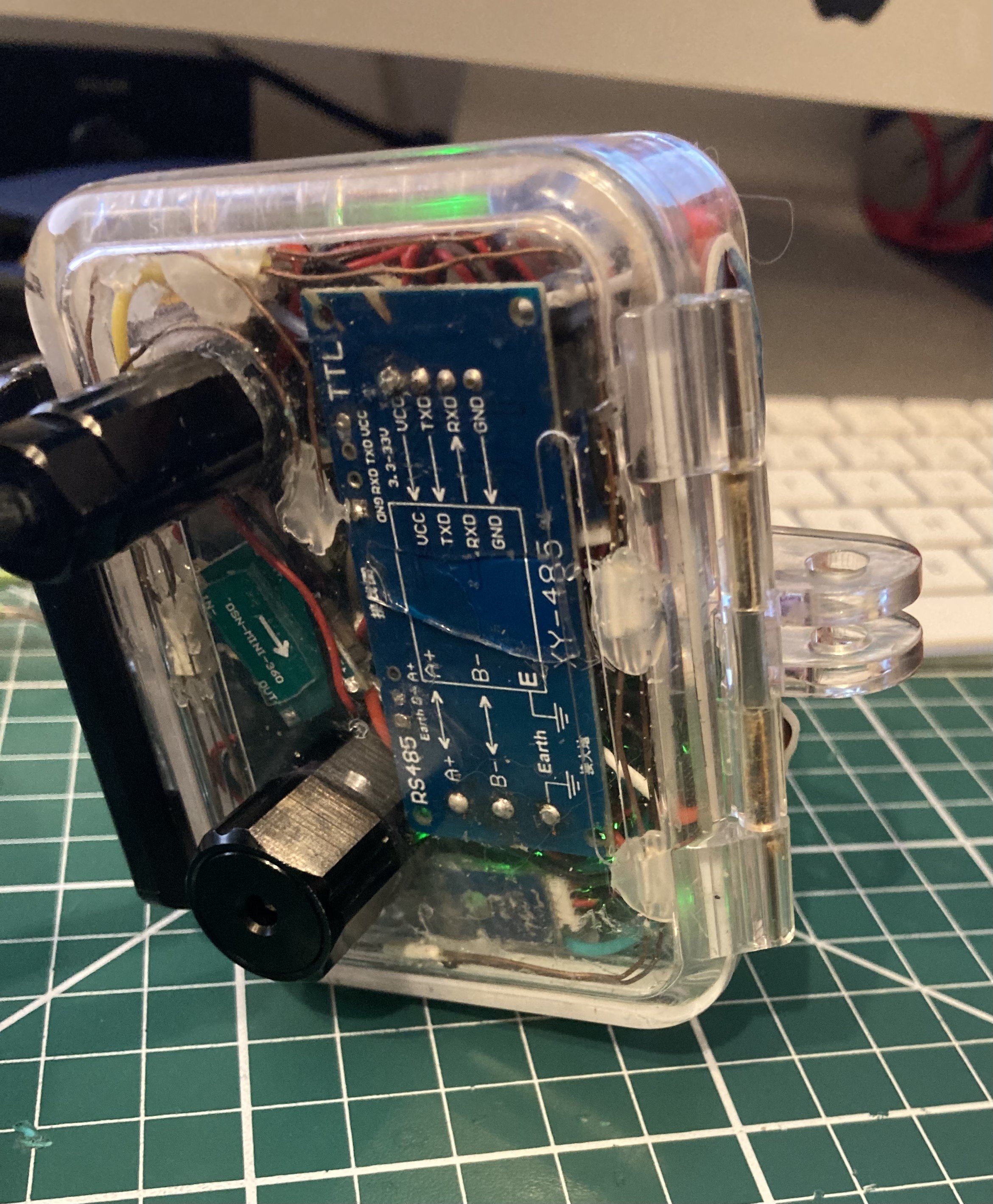
42Step 42: Prepare M5 Stick C Plus Tiger 8-way Micro JST female plug
Connections to the two reed switches, ground and the leak detector are made to the Tiger 8-way Micro JST female plug. See schematic for pins and further details.
![]()
-
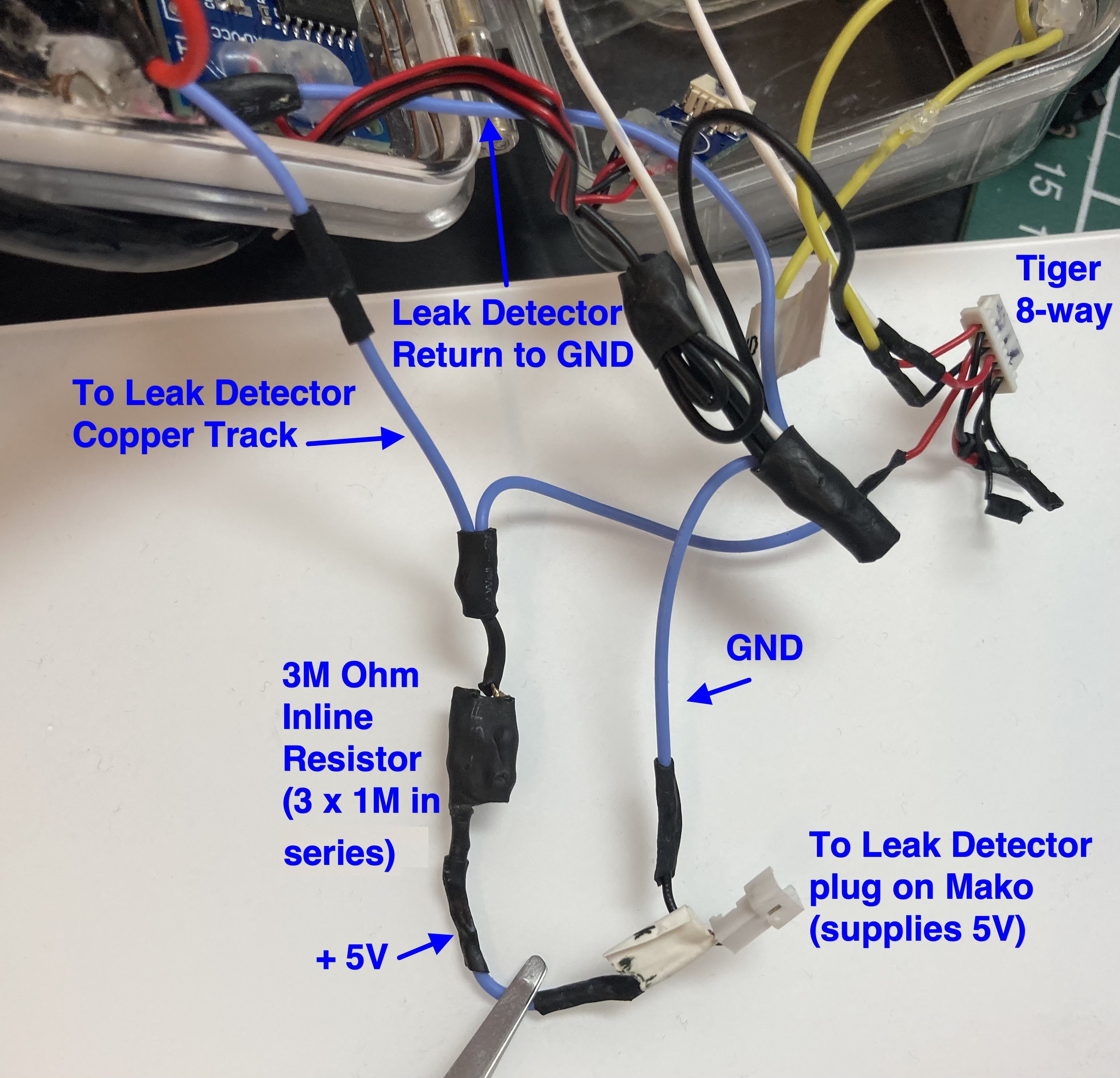
43Step 43 - Add inline resistor for leak detector, hook up leak detector, check reed switches and add USB-C Plugs.
In accordance to the schematic, an inline 3M Ohm resistor is required for the leak detector to operate. Achieve this with 3 x 1M Ohm resistors in series. Also make sure that the leg of each reed switch that is not connected to Tiger M5 is connected to ground (not shown below).
![]()
Both M5 Sticks need a USB-C plug to supply 5V and Ground. Solder wires to two prototyping USB-C Plugs and use rubber mouldable putty or hot glue to mechanically reinforce the connections and to provide a surface to pull the plug out of the socket later. Connect the USB-C power lines into the 5V supply for the enclosure and connect their ground wires to the enclosures ground / 0V.
![]()
-
44Step 44: Upload code to Mako and Tiger M5 Stick C Plus modules
Before inserting the two modules into the enclosure, upload the code for Mako and Tiger M5 Stick C Plus modules using these github repos and the Arduino IDE:
https://github.com/scuba-hacker/mercator-origins-mako
https://github.com/scuba-hacker/mercator-origins-tiger
Mako Arduino library dependencies
M5StickCPlus
AsyncTCP
ESPAsyncWebServer
AsyncElegantOTA
Adafruit_Sensor
Adafruit LIS2MDL
Adafruit LSM303 Accel
Adafruit BME280
Tiger Arduino library dependencies
M5StickCPlus
AsyncTCP
ESPAsyncWebServer
AsyncElegantOTA
Check that both Sticks can be connected to your wife and can be updated Over-the-Air using your local WiFi. Use this URL to connect to each stick for OTA updates:
http://<IP-Address>/update
Once the Sticks are installed in the enclosure it is far preferable to update them OTA avoiding the need to remove them to insert a USB-C data cable.
-
45Step 45: Hardware final checks before assembly.
Check that all 5V and GND connections are made in accordance to the schematic. Check continuity of all soldered connections and that all PCB / HAT pins that are connected on the schematic are wired correctly.
-
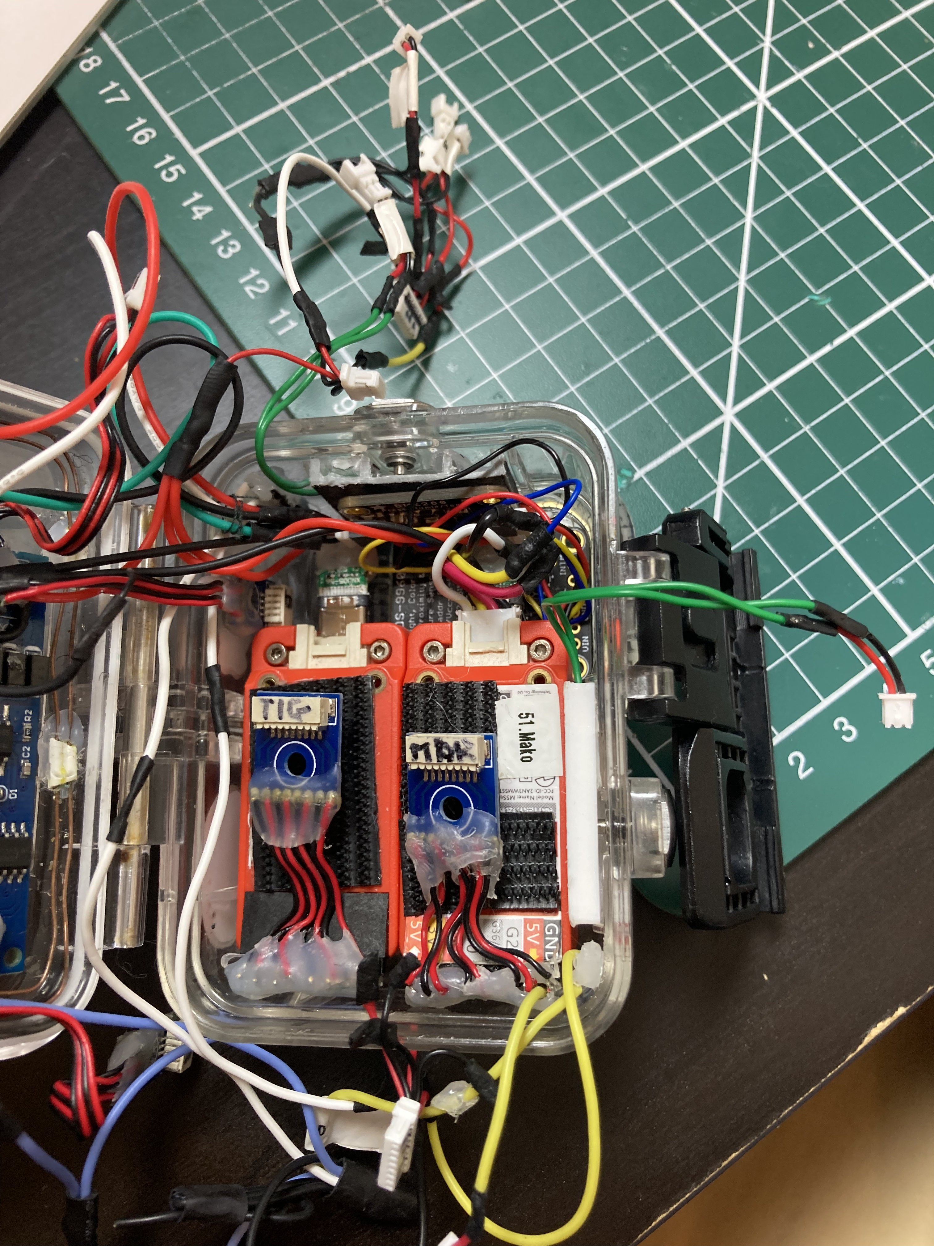
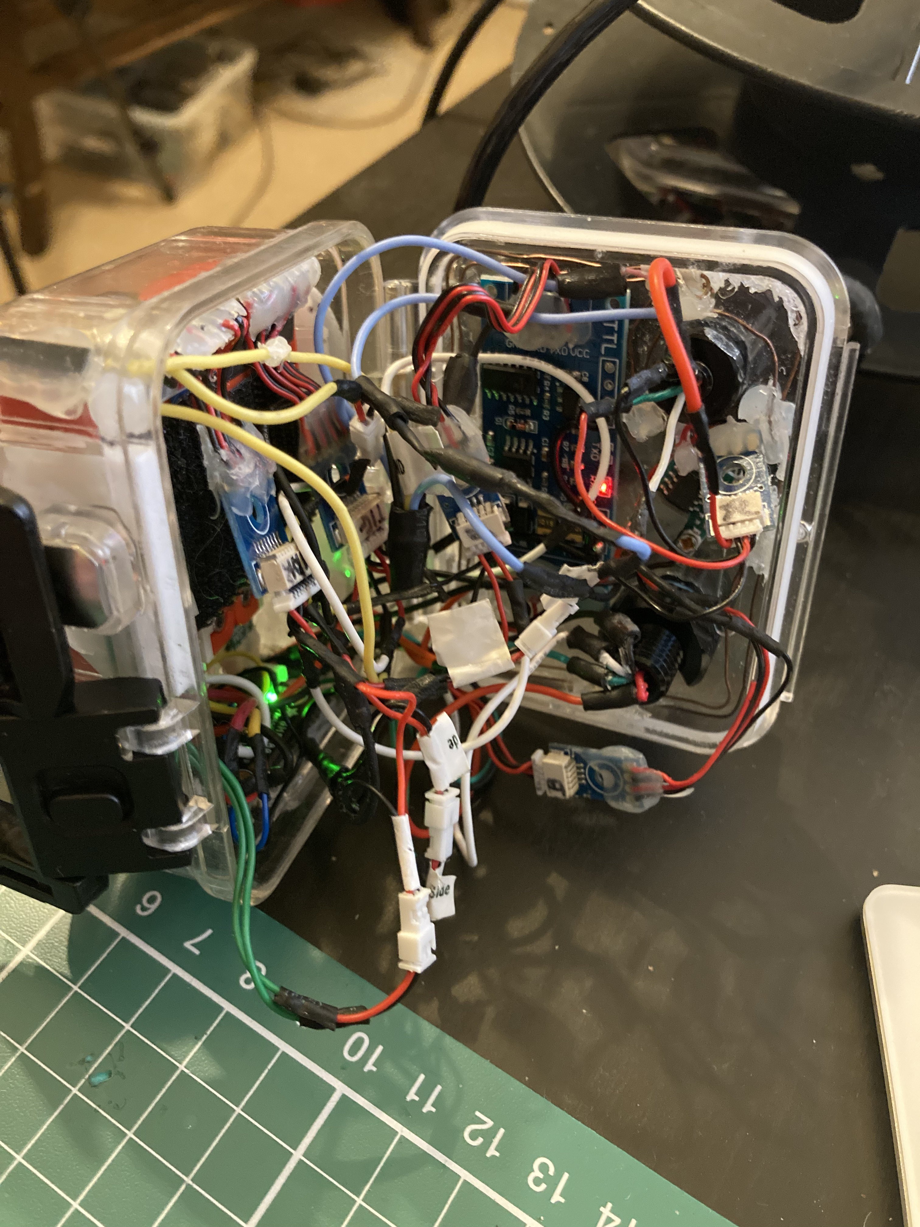
46Step 46: Mount Tiger and Mako M5 Stick C Plus modules
Insert Tiger’s HAT header into Tiger M5 Stick and do the same for Mako M5 Stick. Insert Tiger and Mako’s USB-C Plug. Insert the Grove plug for the I2C sensors into Mako’s Grove Socket.
Apply a 4mm wide strip of 1mm thick nano tape to each of the M5 Stick C Plus just below the display to prepare for the modules to be inserted display down.
Insert Tiger M5 module into the enclosure first at the bottom of the enclosure, followed by Mako (so that Mako is inline with the magnetometer), and connect the respective 8-way Micro JST female plugs. The M5 HAT headers are positioned up against the left wall of the enclosure looking from the front of the case.
Take care not to snag the reed switch wires. Velcro on the back of the Sticks helps to pull them out at a later date.
![]()
-
47Step 47: Connect all Micro JST plugs/sockets.
Connect the plug and sockets for all the below, do not attempt to close the enclosure yet:
Mako HAT 8-way
Tiger HAT 8-way
Side Button 2-way
Top Button 2-way
Leak Detector 2-way
Phototransistor 2-way
‘U’ Connectors 4-way
‘R’ Connectors 4-way (the sub-sea cable penetrator needs re-installing to the enclosure if not already refitted)
‘B’ Connectors 4-way
-
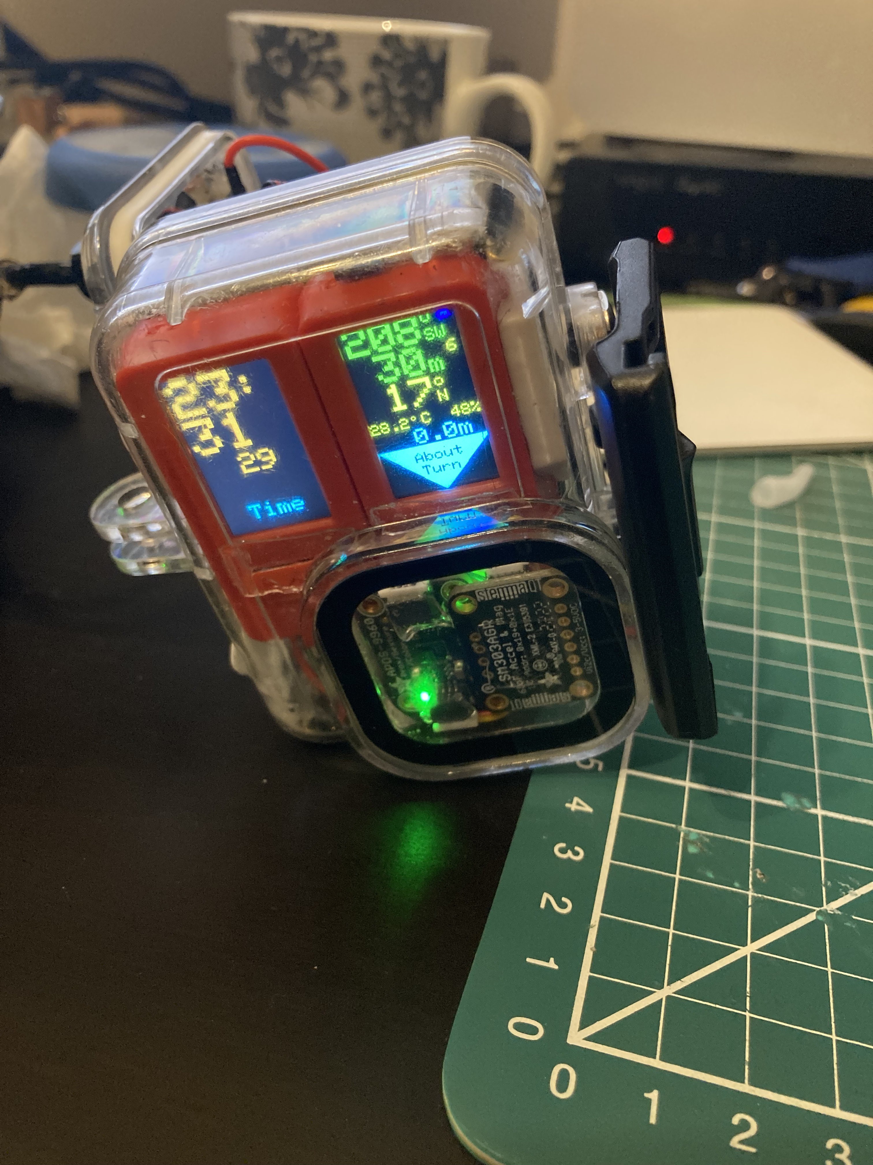
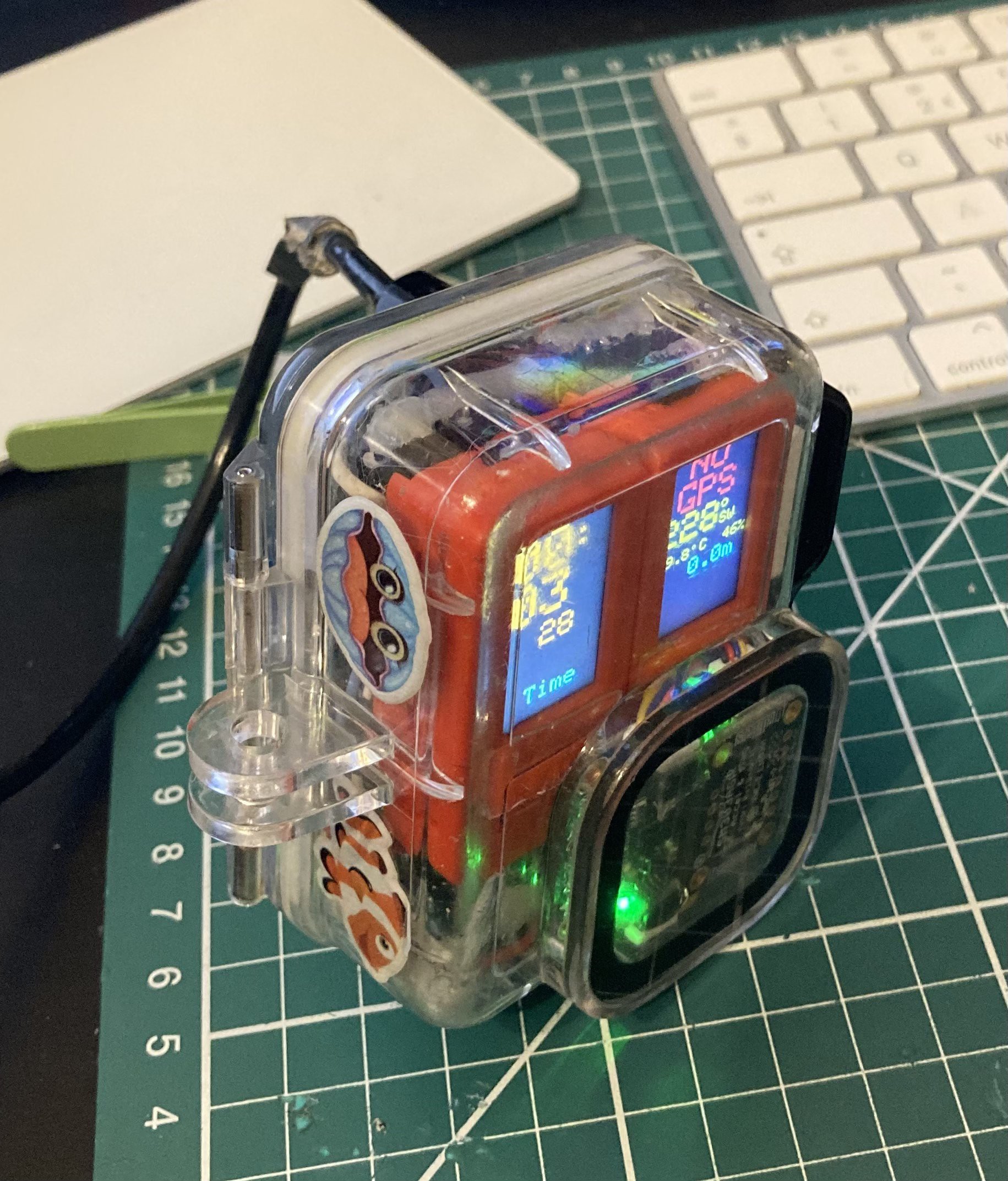
48Step 48: Power-up the float and check Navigation Pod functionality
Check that the 'Top' button works (that is the button shown on the right below), this will cycle through the different displays with a short press.
Check that the 'Side' button works (this button is below the lens of the enclosure), this will show the first feature destination with a short press.
Check the two reed switches by offering up a magnet to each reed switch in turn. Hold the magnet and a count-up timer will be seen in the Tiger display - red for the top-right reed switch, blue for the bottom left reed switch.
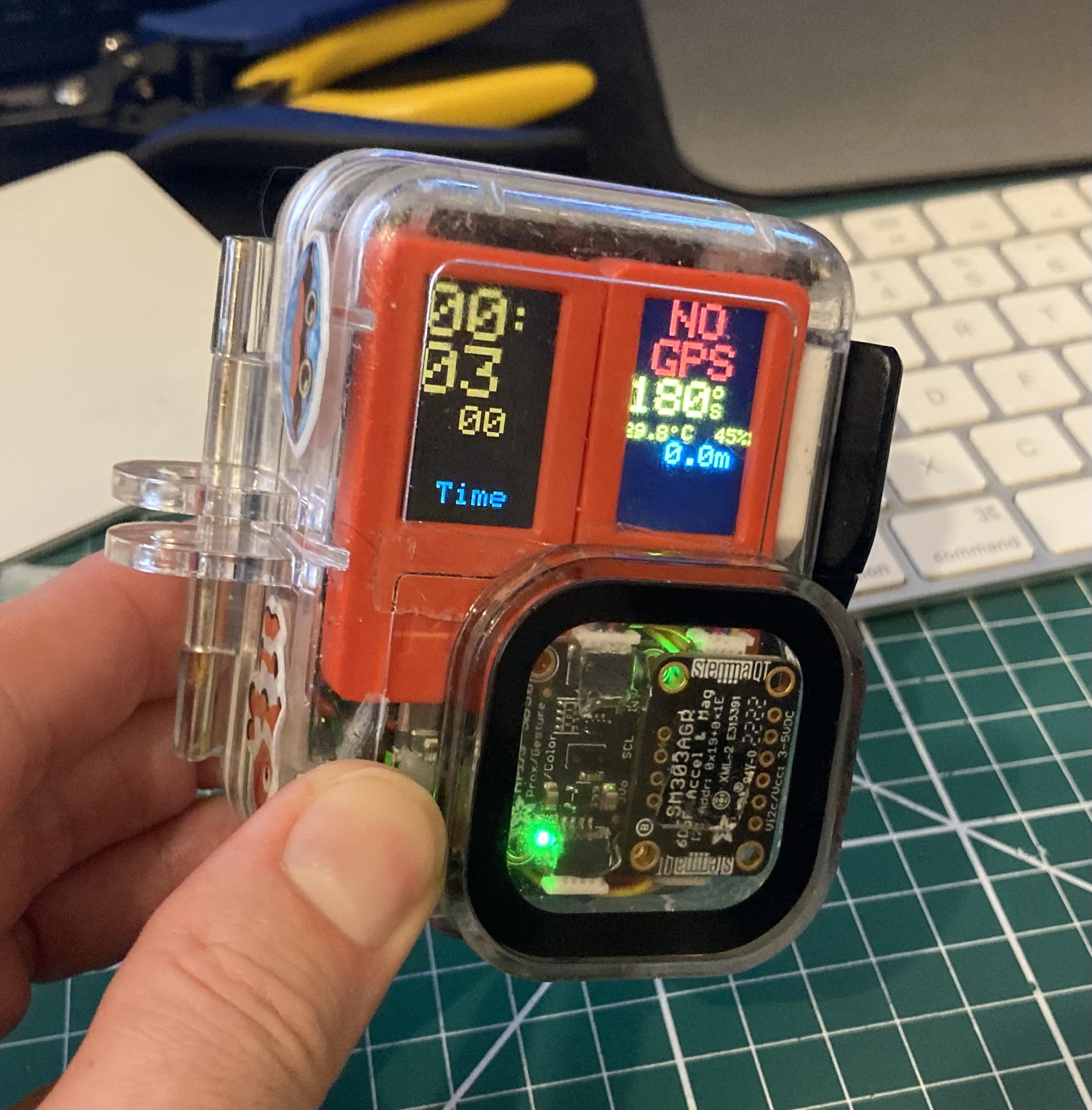
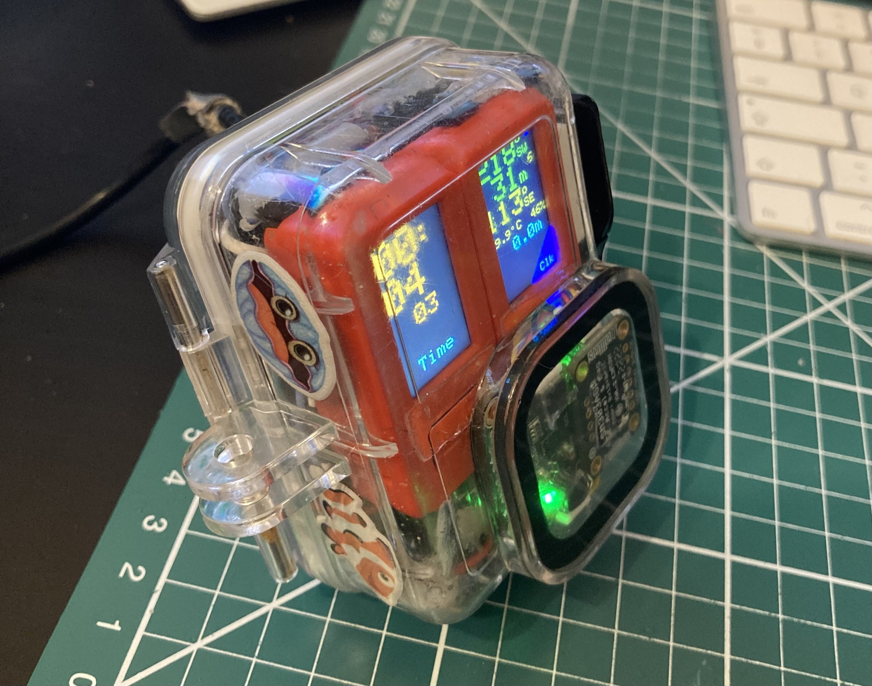
If NO GPS is shown on Mako's M5 display then check the GPS in the float and check Lemon's M5 display in the float for status. The alternative is you will see the display below which shows the heading and distance to first feature target in green.
If the clock on Tiger's display is not correct then check NTP server settings in Tiger configuration.
The temperature, humidity and compass should all be showing good values on the screen as shown below. The depth sensor will only be testable in water!
The leak detector can be tested by shorting the two parallel copper tracks together. The leak alarm will appear on Tiger's display.
![]()
![]()
-
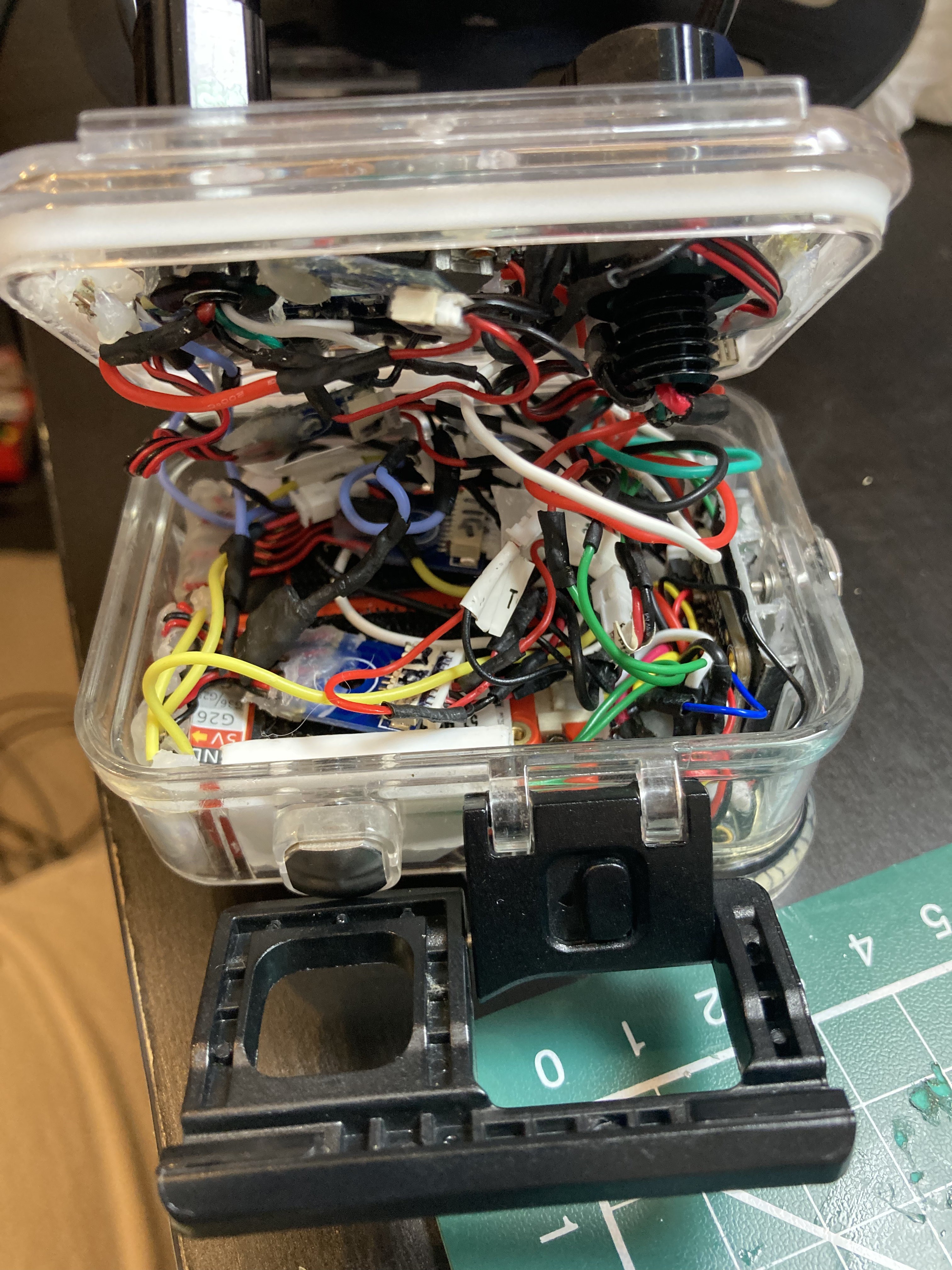
49Step 49: Turn off the power and arrange wires/connectors so that enclosure can be closed
Turn off the power at the float.
Carefully manipulate the wires and connectors in the enclosure so that the back of the enclosure can be closed. Allow a significant time to do this especially to begin with.
Once the enclosure is closed, turn the power back on and repeat the tests in Step 48.
Tips
1. Don't force the back closed.
2. Remove any wires that get caught in the silicone seal, the back will not close if this is the case.
3. Check that connectors are not getting in the way of the penetrator or depth sensor when the back closes. Move them aside if they are.
4. Cotton thread can be used to bundle together wires to make it easier to close the back without wires getting caught atn the edges.
5. Be patient, if there is too much resistance closing the enclosure then you may need to cut some of the wires shorter. Too much wire in the enclosure will prevent closure.
Ready for closing...
![]()
Nearly there...
![]()
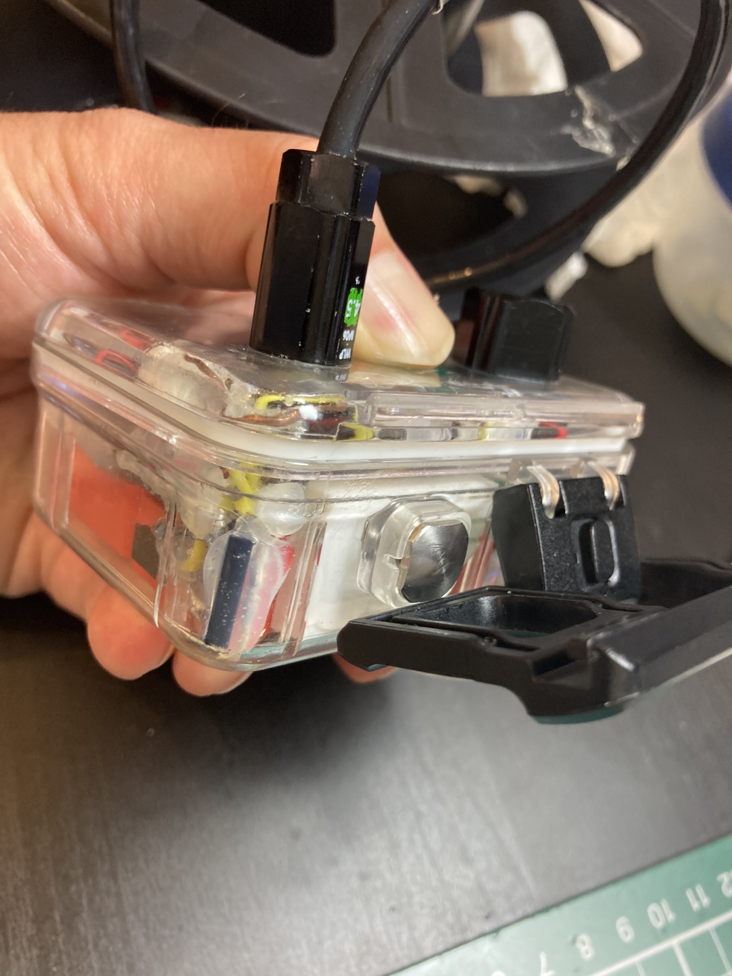
Closed without being forced, just need to clip the latch.
![]()
Closure complete!
![]()
Final checks, power up once more... all good!
![]()
![]()
![]()
![]()
-
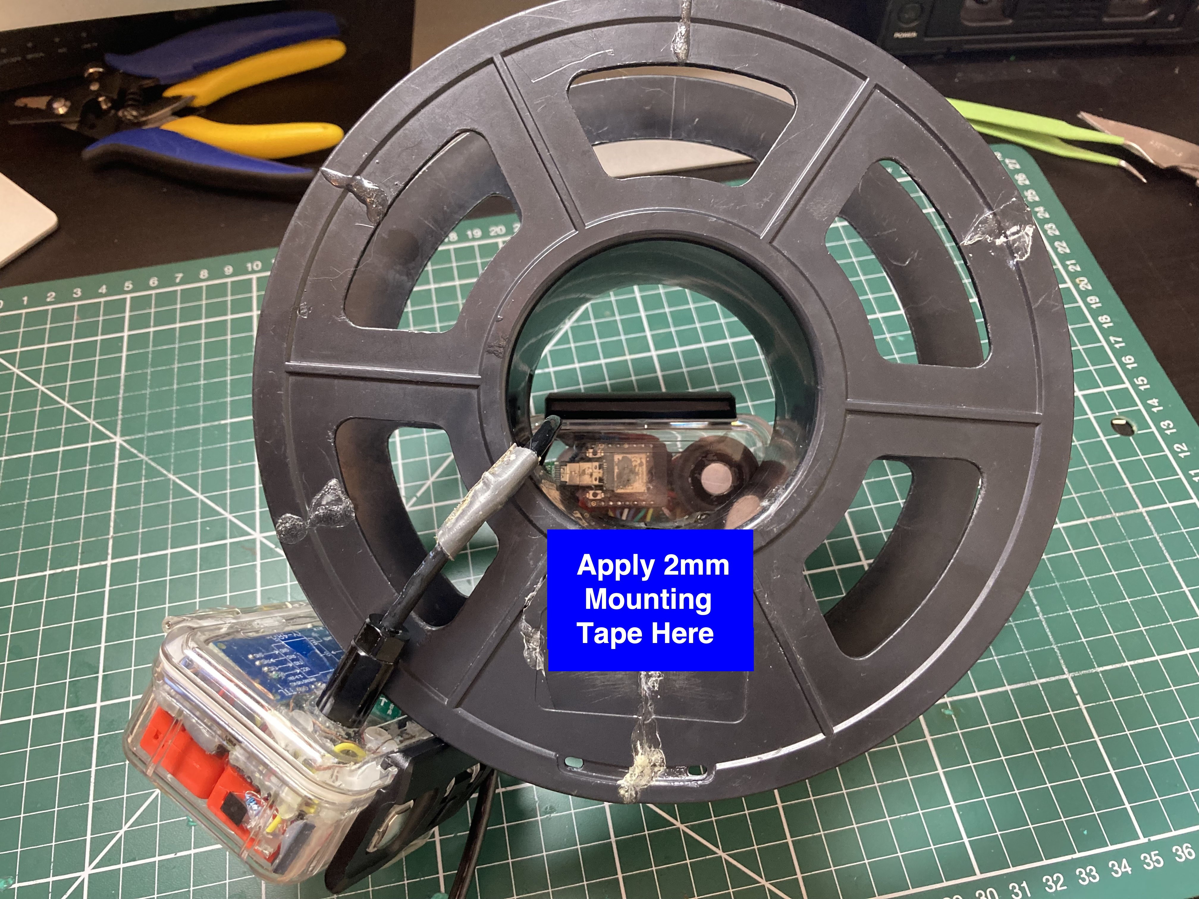
50Step 50: Mount the Navigation Pod on the Spool
Using 2mm thick Nano Tape, mount the navigation on the pod, taking care to thread the sub-sea cable back through the slot cut in the centre of the spool. (Ignore the audio pod attached to the back of the spool seen here).
![]()
Navigation pod mounted into place:
![]()
"Mercator Origins": Sat Nav & Telemetry for Divers
Want to map your dive? Want to navigate like a pro? Even if you are vision-impaired, this will empower you to navigate our underwater world.


Discussions
Become a Hackaday.io Member
Create an account to leave a comment. Already have an account? Log In.