 Mark B Jones
-
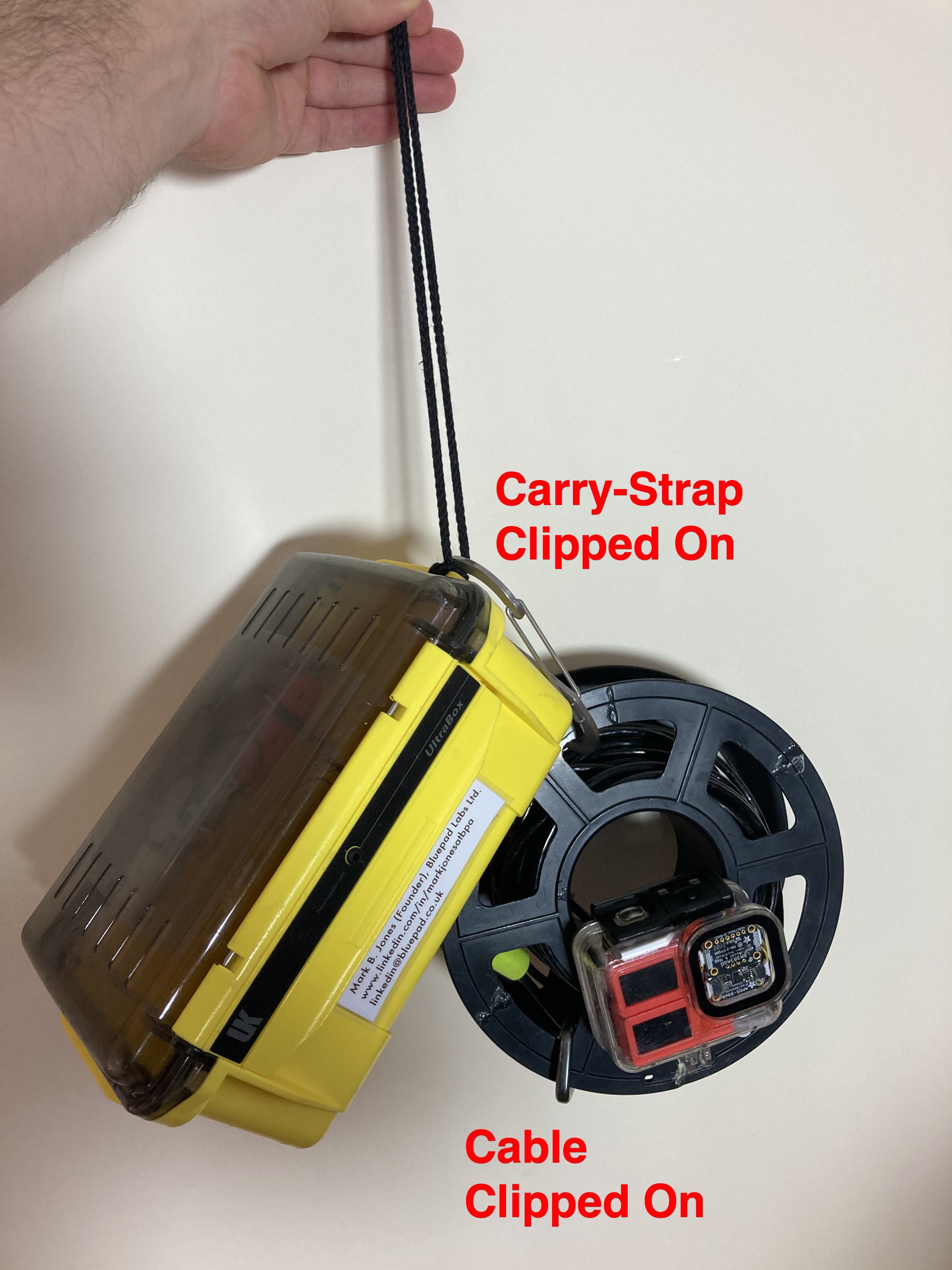
51Step 51: Coil cable on spool and clip off with caribiners
![]()
![]()
-
52Step 52: Gather components for Audio Pod 2 Build
(Audio Pod 1 is disregarded as the single speaker solution is not as audible underwater as I would have liked, especially when wearing a neoprene hood worn for cold water)
Non-OEM GoPro 10 enclosure, solder tagged 18350 lithium cell 3.6V 3500mAh,automative miniature 5 Amp fuse, DFRobot Beetle ESP32-C3, 512MB Flash module, 3 x Audio Exciters, 3 x I2S Amps, 1 x 1 Amp 3.6V to 5V Step Up Regulator, 1 x 2 Amp 3.6V Step Up Regulator, USB-C Prototyping plug, 4-way Micro JST female plug and male socket connectors, 1 x USB-A Plug, LEDs and Resistors as per schematic, 1mm nano tape.
-
53Step 53: Solder the system together as per the schematic.
Note the use of a PCB female header for switching power on/off shown in step 60, where operation is described There is insufficient space for physical switches inside the enclosure, although the enclosure buttons could be employed at a later date as there is sufficient space for two button mounts to be inserted.
Solder LEDs and resistors directly to the pins of the corresponding PCBs, as per the schematic.
Solder the Micro JST plug connector to the USB-C Prototyping plug using all 4 pins – see photo in step 54. Make up a wiring harness composed of a USB-A plug and the Micro JST socket connector to program the Beetle MCU.
See photos in steps 58 and 59 for example wiring configuration and mounting locations for PCBs.
![]()
-
54Step 54: Power up the circuit and verify the LEDs light
- Beetle Blue LED flashes (default mode before code upload)
- Red LED for 2 Amp Regulator
- Green LED for 1 Amp Regulator
-
55Step 55: Sounds and Code upload to MCU
Step 55 Download the Simple FTP Server project and ‘Silky’ MCU code and sounds from github.
Github repos:
Simple FTP File Server
https://github.com/xreef/SimpleFTPServer
Guidance from original author:
https://mischianti.org/2020/02/08/ftp-server-on-esp8266-and-esp32/
Make a one line change to SimpleFTPServer/FtpServerKey.h
Change Line 63 from this:
#define DEFAULT_STORAGE_TYPE_ESP32 STORAGE_FFATTo this:
#define DEFAULT_STORAGE_TYPE_ESP32 STORAGE_SDMercator Origins Silky repo
https://github.com/scuba-hacker/mercator-origins-silky
Silky library dependencies: None
-
56Step 56: Upload the FTP Server code to the MCU using Arduino IDE.
Upload the FTP Server code to the MCU using Arduino IDE. Using your favourite FTP Client, eg FileZilla on Windows or CyberDuck on Mac, upload the guidance sounds to the root of the 512 MB Flash module.
-
57Step 57: Upload the Mercator Origins Silky code to the Beetle MCU
Upload the Mercator Origins Silky code to the Beetle MCU and using the Arduino IDE serial monitor follow the instructions to test audio playback.
Once tested power down the system and disconnect the USB-C plug from the Beetle.
-
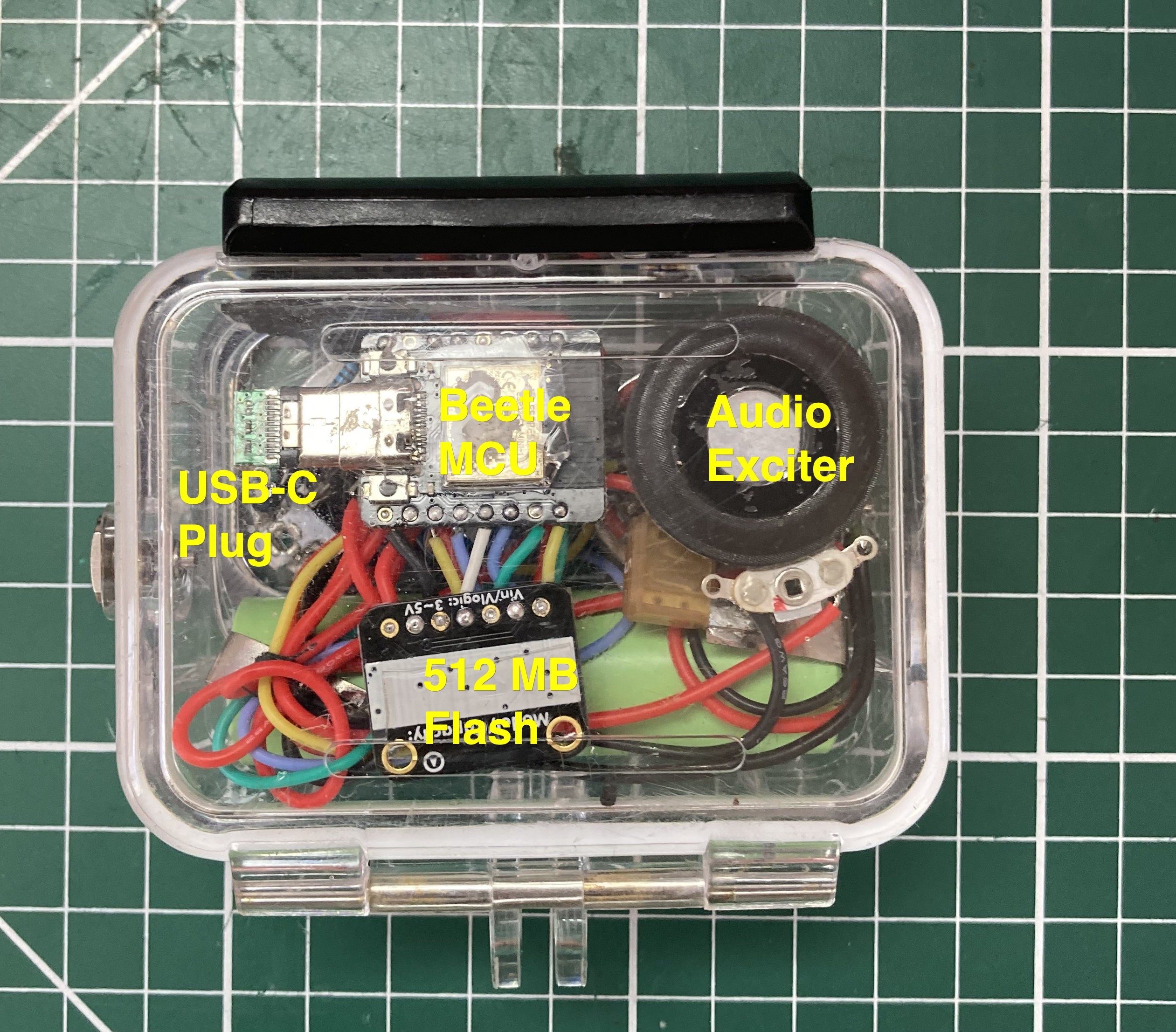
58Step 58: Mount components in the inside of the door of the enclosure
Mount the components in the door of the enclosure using 1mm nano tape, except for the exiciter which has its own double-sided tape already applied for affixing to the enclosure.: 1 x audio exciter, Beetle ESP32-C3, 512 MB Flash and insert the USB-C plug into the Beetle. Once the exciter is mounted it is unlikely to be removable again without damaging it.
![]()
![]()
-
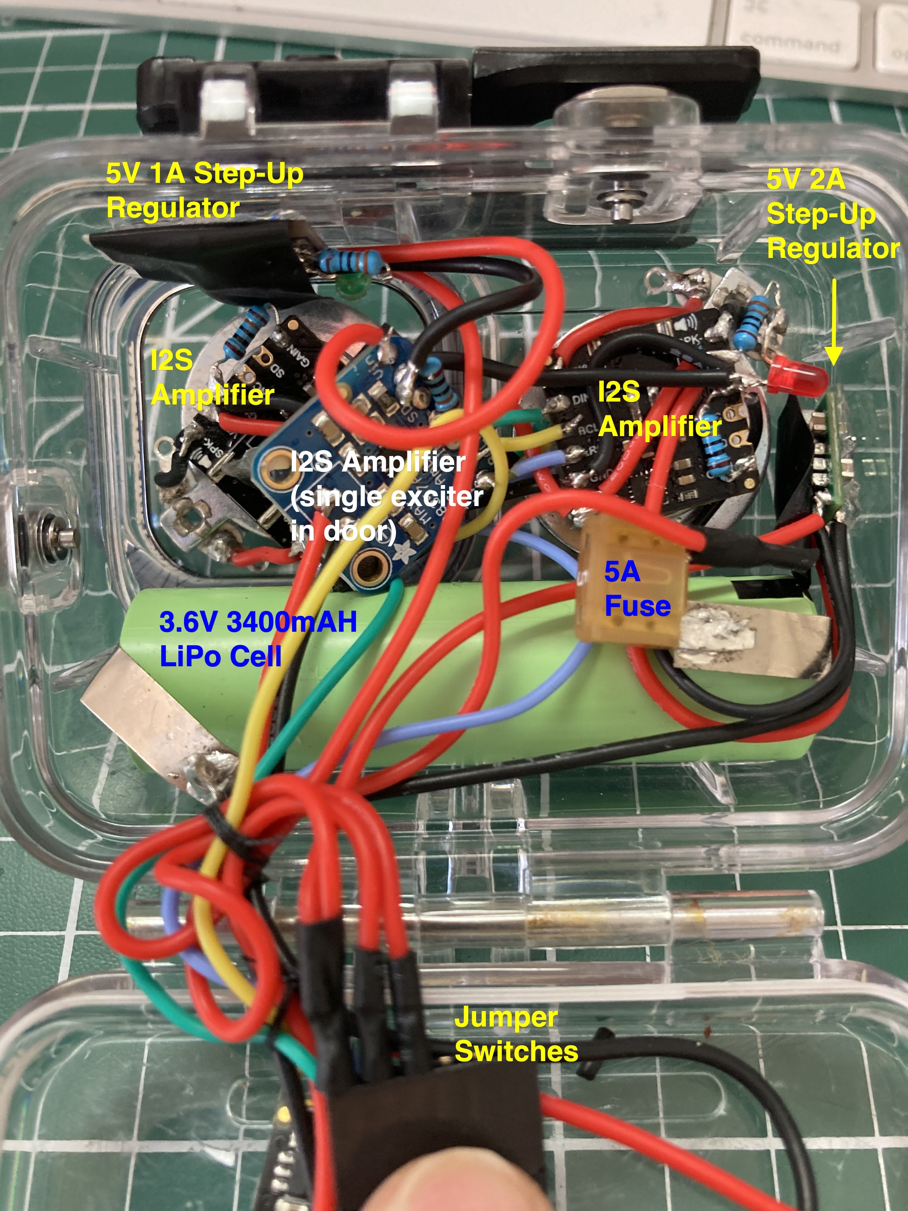
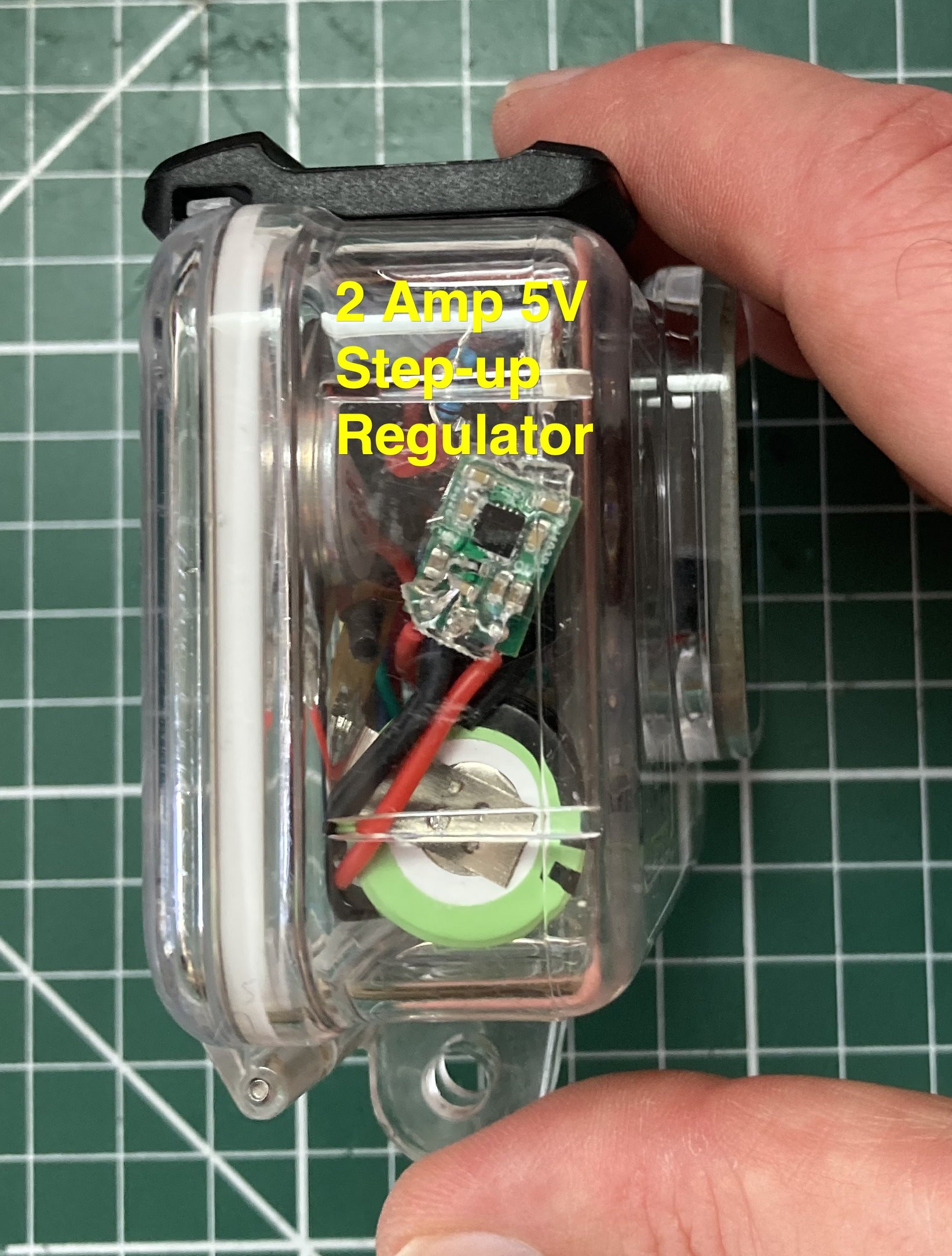
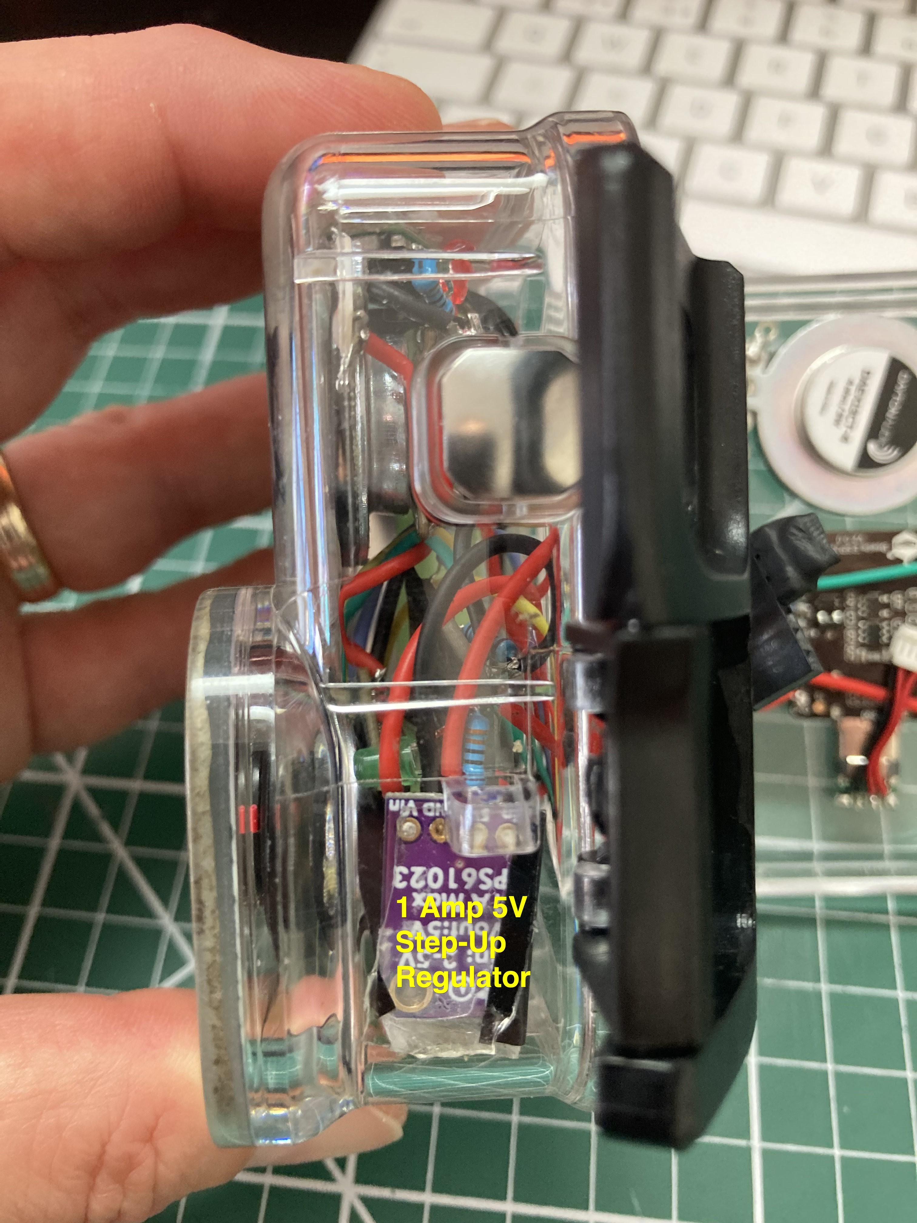
59Step 59: Mount remaining components in the body of the enclosure
Mount the remaining components in the body of the enclosure using 1mm nano tape. The two exciters are oriented as shown to allow for convenient wire placement. The exciters have their own double-sided tape already applied for affixing to the enclosure. Once the exciters are mounted they are unlikely to be removable again without damaging them. Use insulation tape on the back of the step-up regulators for extra protection from shorts.
![]()
![]()
![]()
![]()
![]()
![]()
-
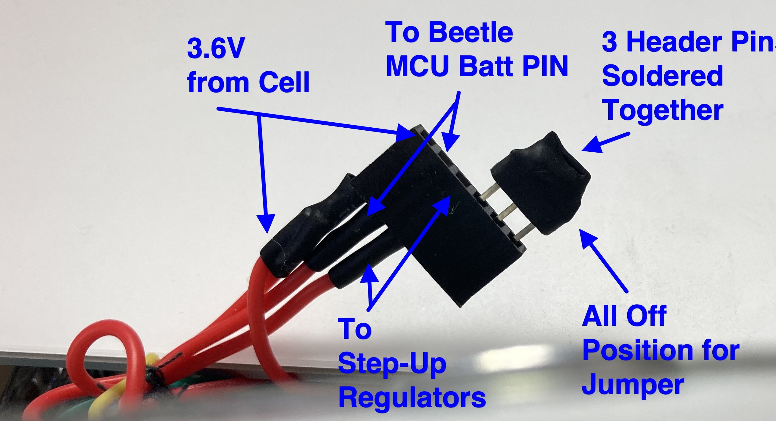
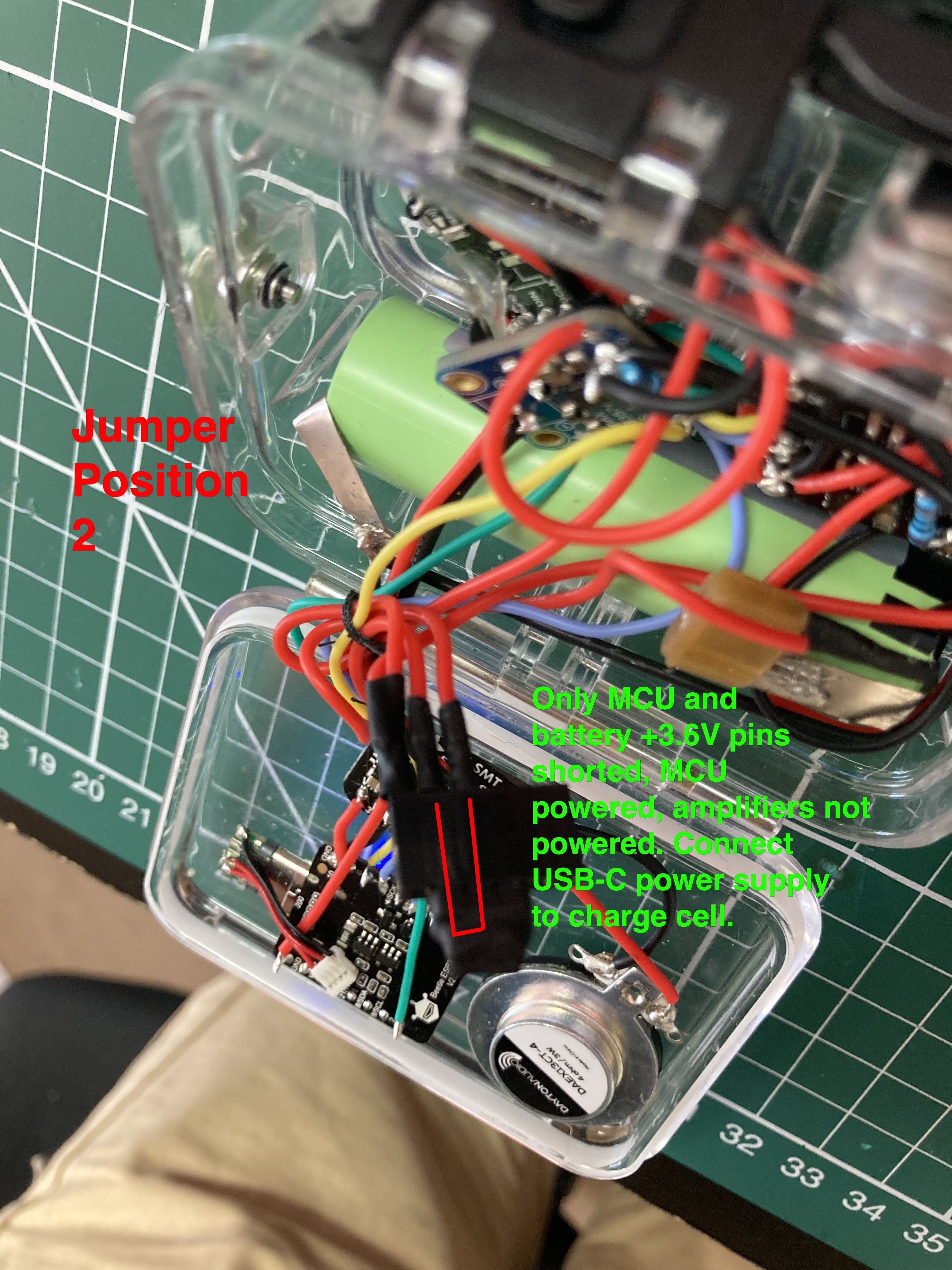
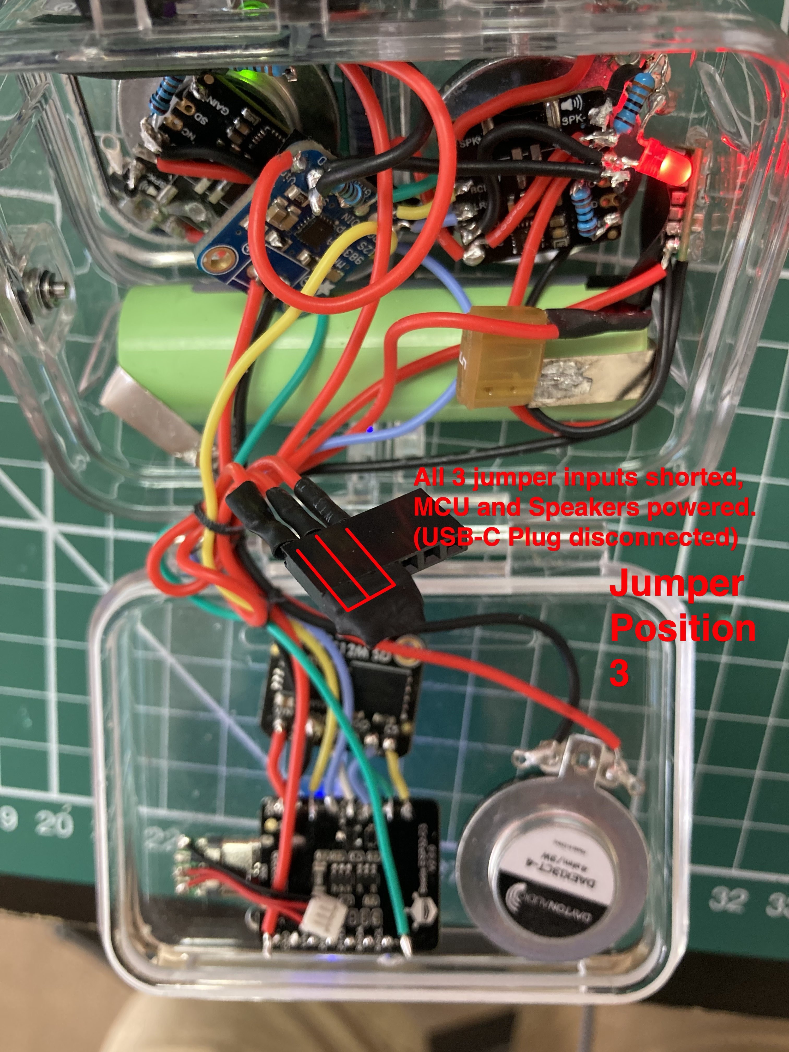
60Step 60: Configuration and operation of the on/off header jumper
The jumper is needed because in order to charge the cell using the Beetle ESP32-C3's battery charger regulator there must be no other devices connected to the cell other than the MCU (jumper position 2). The USB-C 5V input to the Beetle is used to automatically charge the cell. When the cell isn't charging and the system is fully operational then jumper position 3 is used. Jumper position 1 is all system powered down.
The jumper consists of a 6 pin female inline header and a 3 pin regular header that has its 3 pins soldered together as a short. There are three configurations.
- All 3 inputs off. System completely powered down.
- MCU and Battery 3.6V lines are shorted, only MCU is powered – not the step-up regulators or amplifiers. Battery can be charged with USB-C cable connection, allow 7 hours charge time as the Beetle output is 500mAh and the cell is 3500mAh capacity. Code can also be uploaded through USB-C, this is the preferred mode for uploading code.
- All 3 inputs are shorted to power-up both the MCU and the step-up regulators to power the amplifiers. This is the fully operational mode of the audio system. The USB-C connection will not effectively charge the cell in this configuration as the batt pin of the Beetle needs to only be connected to the cell at this time. Code can be uploaded in this configuration.
![]()
![]()
![]()
"Mercator Origins": Sat Nav & Telemetry for Divers
Want to map your dive? Want to navigate like a pro? Even if you are vision-impaired, this will empower you to navigate our underwater world.


Discussions
Become a Hackaday.io Member
Create an account to leave a comment. Already have an account? Log In.