 AIRPOCKET
-
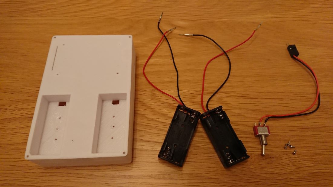
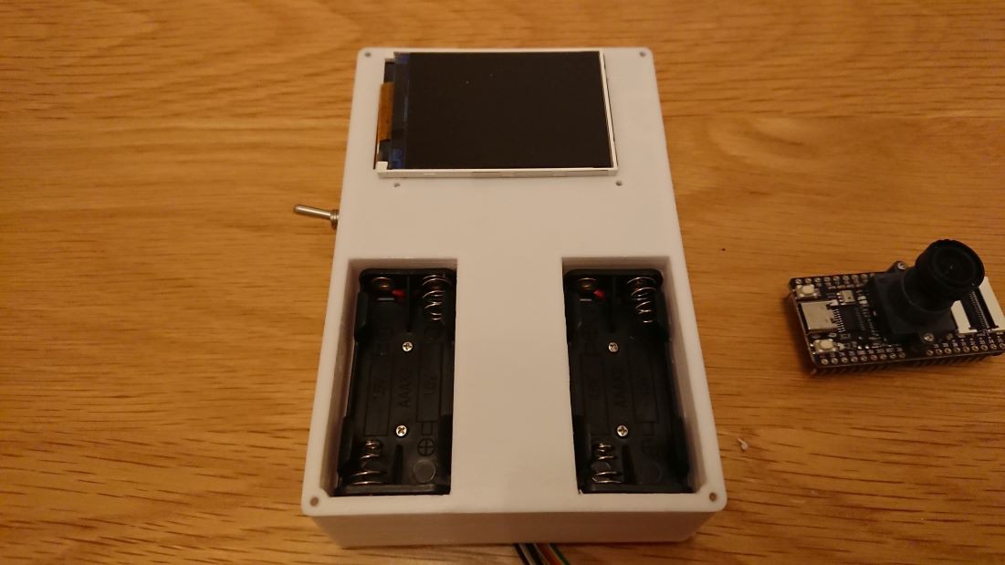
1Installation of the Battery Box
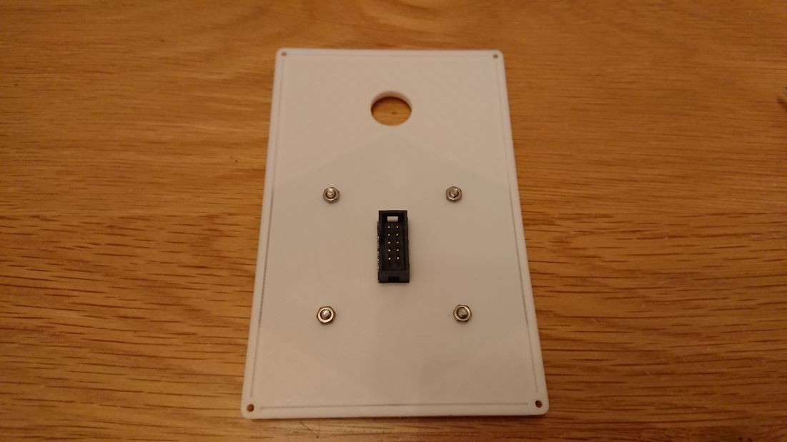
Attach two battery boxes containing two AAA batteries each using screws.
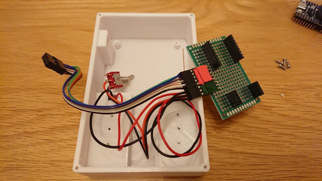
Connect the power toggle switch cable, link four batteries and the switch in series, and construct a circuit that connects to the microcontroller's VCC and GND
![]()
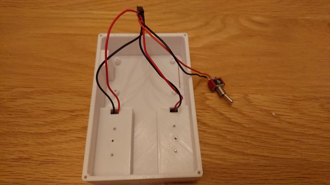
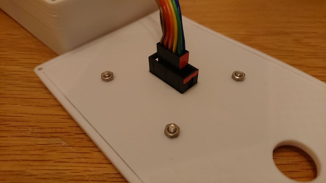
The cables are threaded through the holes in the enclosure and pulled into the interior of the enclosure.
![]()
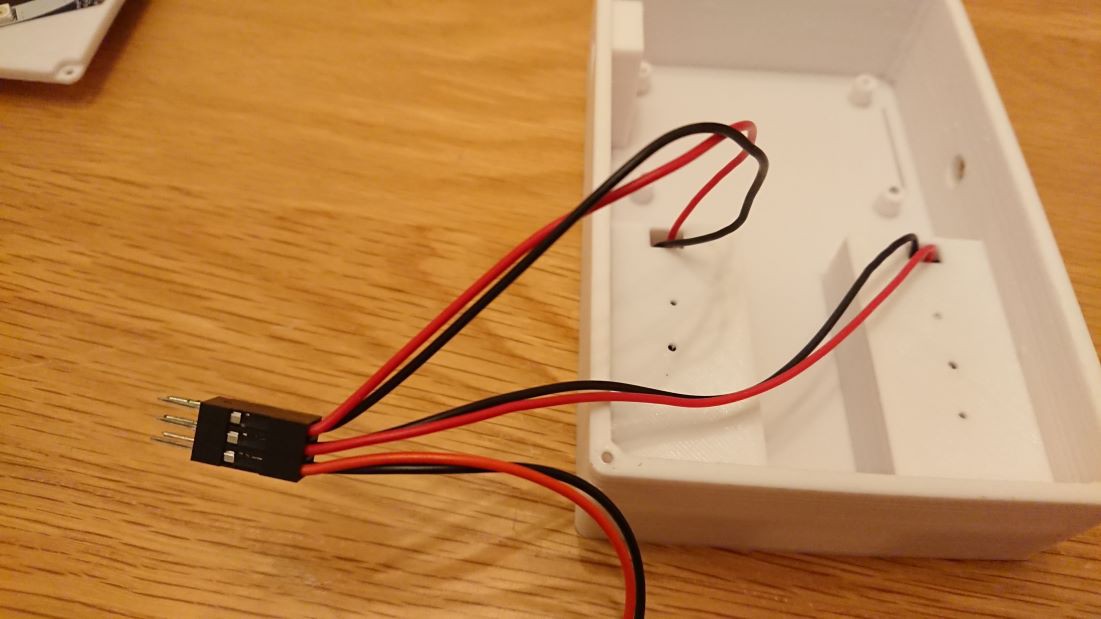
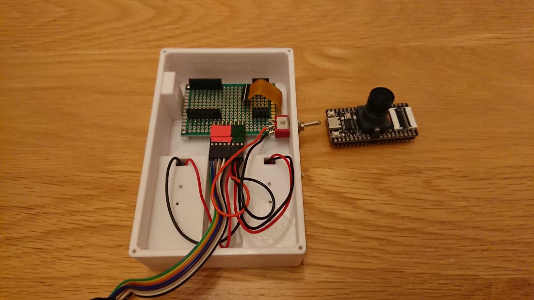
The connectors are consolidated into a 2x3 PIN QI connector. As the toggle switch interferes with the board for controller fixation, it will not be secured in place; only the wiring will be done.
![]()
-
2Board Installation
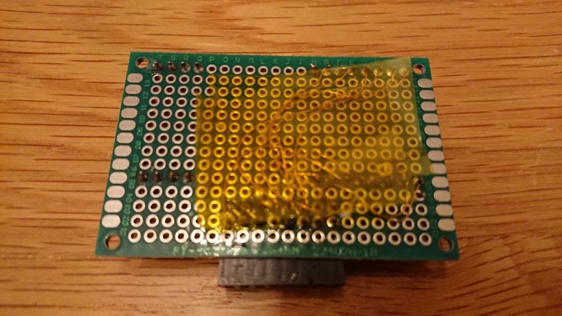
The board has been fabricated using a universal board.
The universal board serves three purposes.
1. Securing the Microcontroller Board
2. Wiring the Power Supply to the Microcontroller.
- 3. Connecting the Microphone Array Board to the Microcontroller.
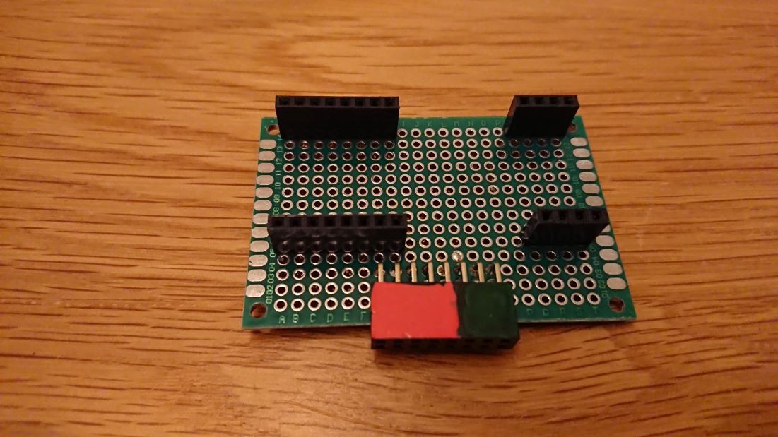
To secure the microcontroller, arrange the pin sockets as shown in the photo.
![]()
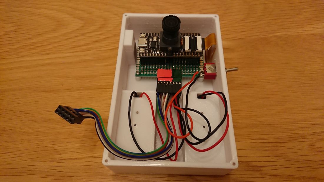
Under the board, there is a 2x8 PIN QI connector. The red-highlighted 2x8 PIN section is for connecting to the microphone array board, while the green 2x3 PIN is for power supply. The power supply is wired to allow the battery and switch to be connected in series to VCC and GND.
![]()
First, insert the cables for the power line and the sensor, then secure the board inside the enclosure.
![]()
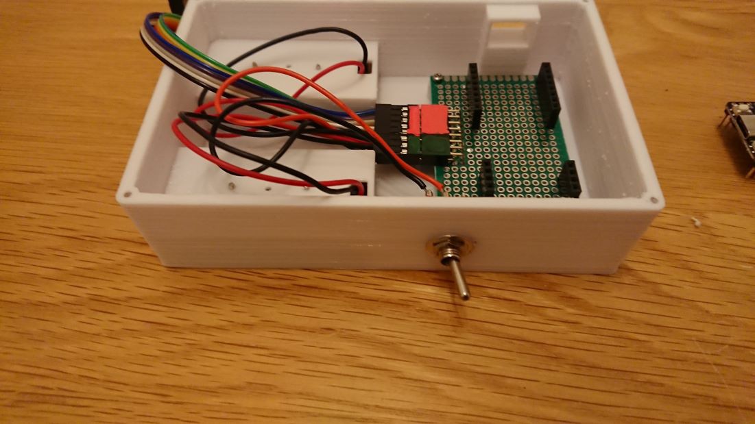
Once the board is secured, proceed to fix the toggle switch in place.
![]()
-
3Attach the Microcontroller Board.
Attach the display to the back of the enclosure using double-sided tape. Thread the cables through the slit into the interior of the enclosure.
![]()
Attach the microcontroller board to the fixation board.
![]()
After attaching the microcontroller board, secure the FPC (Flexible Printed Circuit) of the display to the connector.
![]()
-
4Install the Microphone Array Board
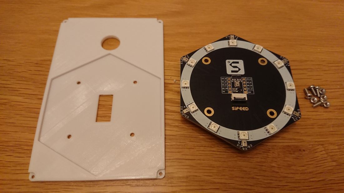
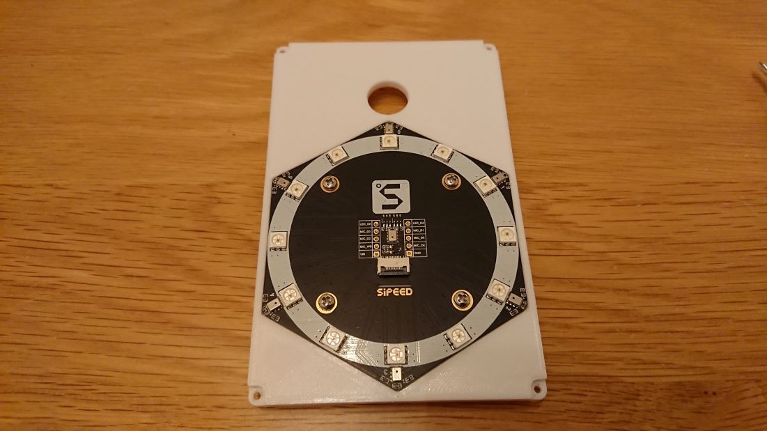
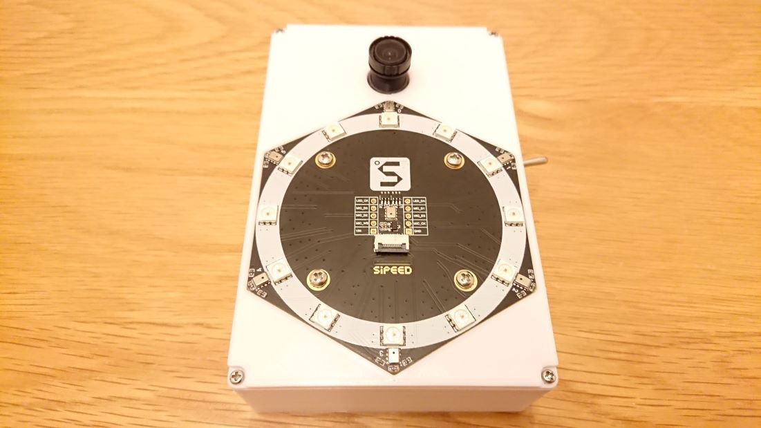
Attach the microphone array board to the front panel. It can be secured with four screws and nuts.
![]()
![]()
![]()
Connect the microphone array board to the microcontroller. It's a good idea to mark the connectors to ensure the correct orientation.
![]()
The pin configuration for the connection points is as follows, according to the following table.
MaixBit Mic Array PIN23 MIC_D0 PIN22 MIC_D1 PIN21 MIC_D2 PIN20 MIC_D3 PIN19 MIC_WS PIN18 MIC_BCK PIN17 LED_CK PIN15 LED_DA 3V3 VIN GND GND After connecting the cables, secure the front panel to the enclosure with screws.
![]()
-
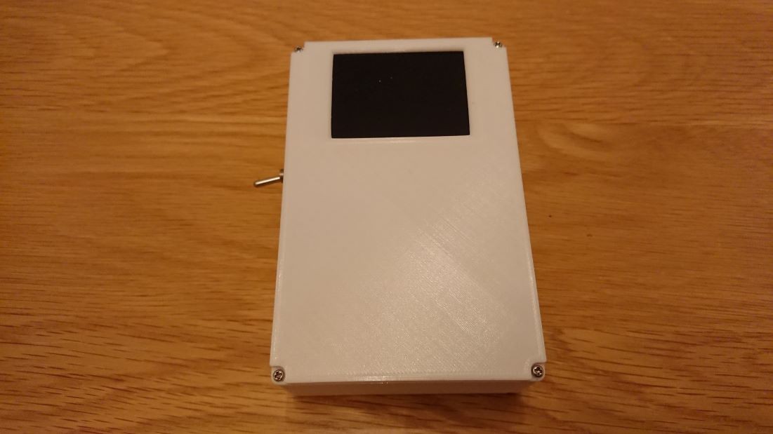
5Attach the back panel and replace the lens.
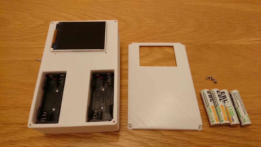
Insert the batteries and attach the back panel.
![]()
Secure the back panel with four screws, similar to the front panel.
![]()
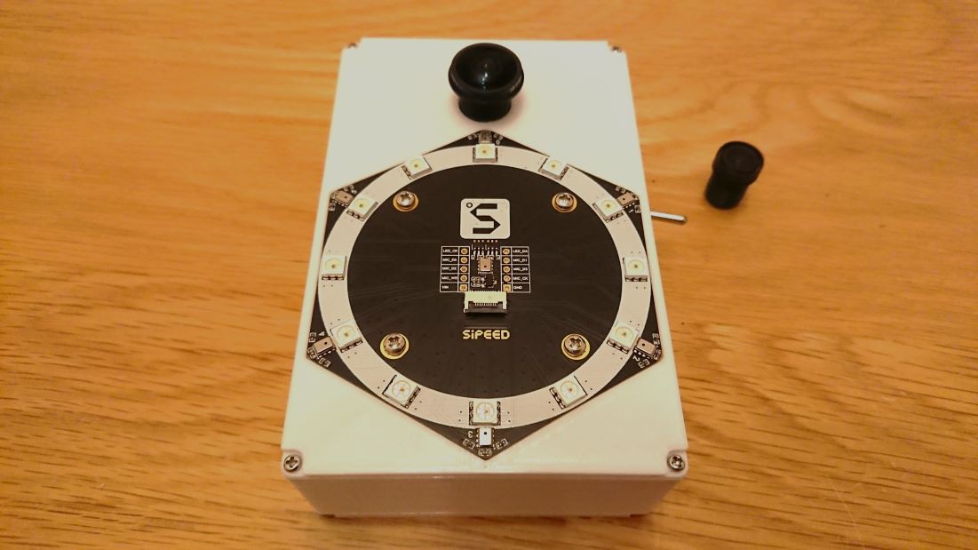
Once the back panel is in place, switch out the camera lens for the wide-angle lens.
![]()
The lens is of the M12 screw type.
That concludes the process.
Portable Sound Visualization AR Device
A portable AR device that superimposes an image showing the location of a sound source on an image captured by a camera.
Discussions
Become a Hackaday.io Member
Create an account to leave a comment. Already have an account? Log In.