-
1Chassis parts preparation
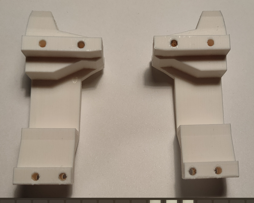
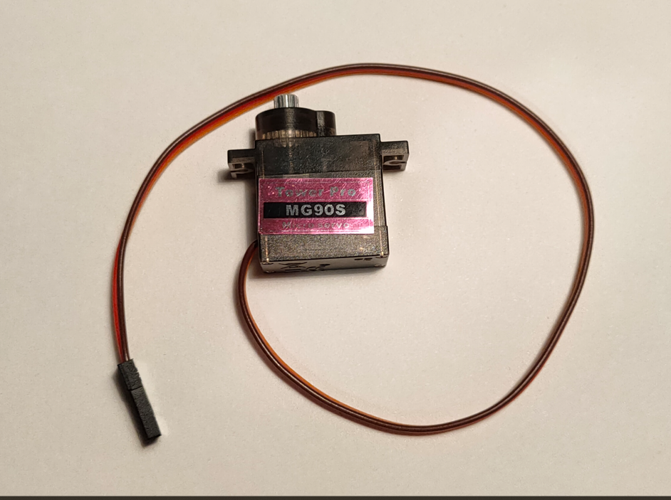
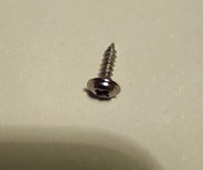
Prepare chassis 3D printed parts - left and right, 2x MG90S servos, 4x servo mounting screws (servos are sold with screws included)
![]()
![]()
![]()
-
2Assemble chassis halves
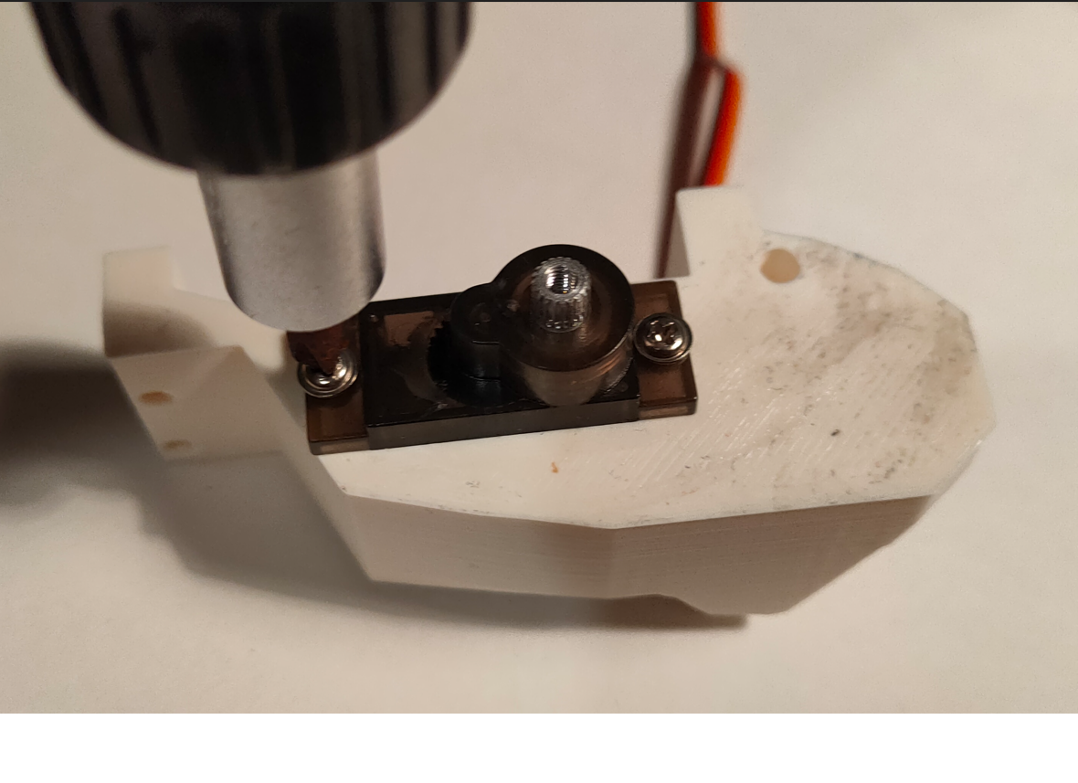
Put the servo in pocket of 3D printed part. They will fit only in one direction, there is undercut for the servo cables to fit. Screw it in using screws - be careful not to damage screw heads as they are made of not really the highest quality material. Repeat for the other side.
![]()
-
3Prepare Cell cables
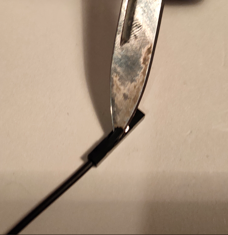
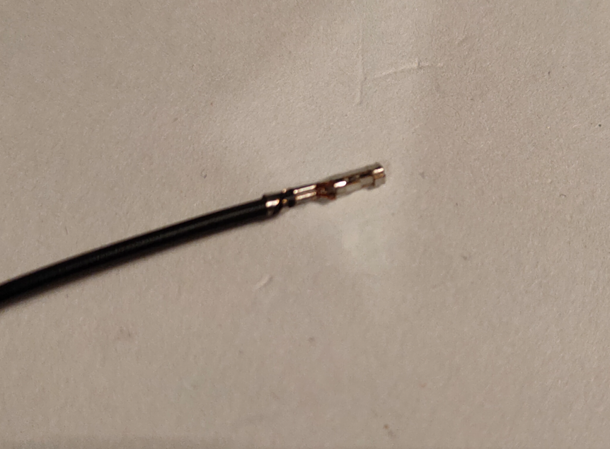
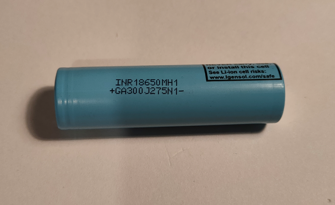
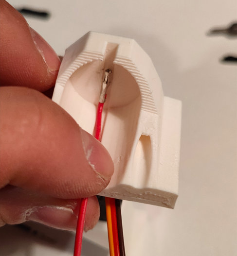
Take two female to female jumper cables, and remove plastic covers - only from one side of the cable. We'll use the exposed connector as Li-Ion cell contacts.
![]()
![]()
-
4Assemble slider
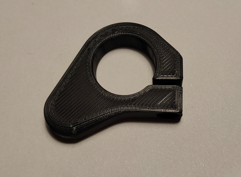
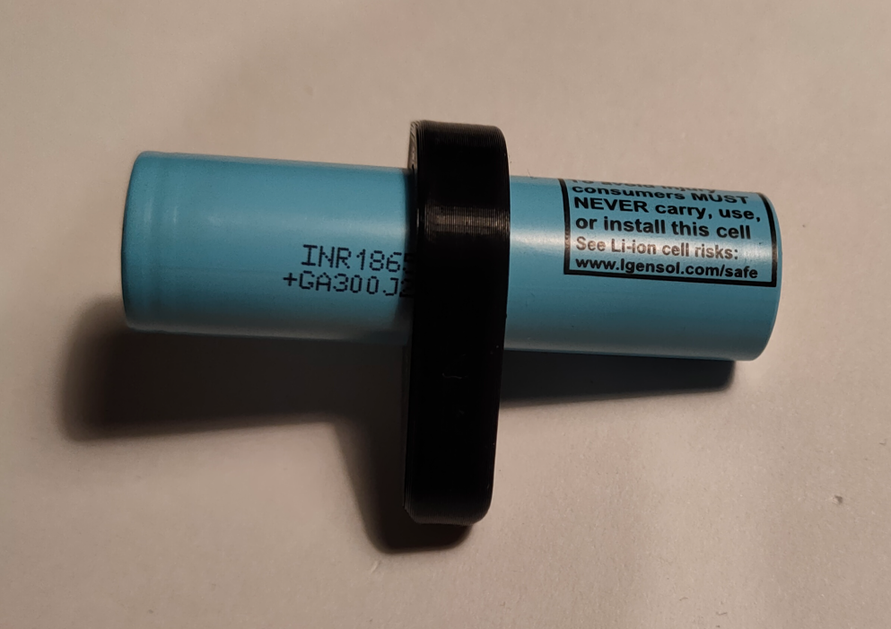
Take the slider and put it on the cell. Note the orientation - after assembly tightening bolt should be closer to the robot center, not on the outside.
![]()
![]()
![]()
-
5Chassis assembly
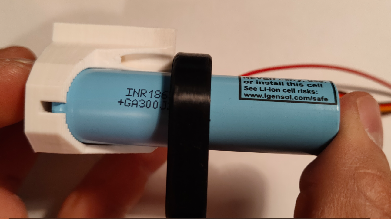
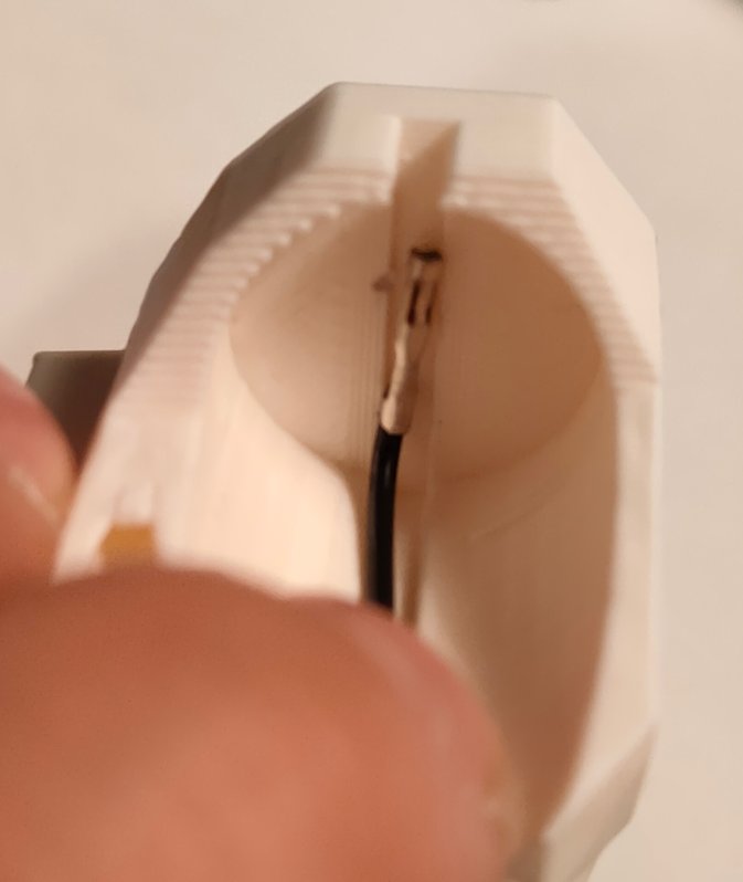
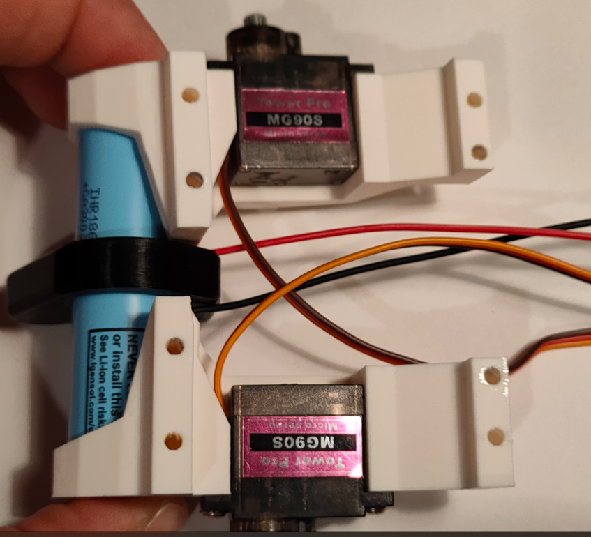
This one is tricky - take jumper wires and bent them to fit inside cell pockets in chassis parts. There is undercut to guide the cable. Red cable should be connected to the positive terminal of the cell, so make sure you put the slider the correct way. Put the cell inside the pocket, clamping the red wire. Then attach the other half in a similar way - first, put the cable inside and then clamp bot halves together.
![]()
![]()
![]()
![]()
-
6Locking chassis with main PCB
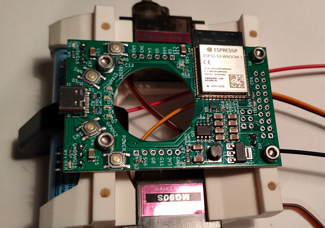
Take the PCB and put it on the top of previous assembly. Put M3x10 bolts trough the holes - they can be tight, and if cables slipped out of their pockets, this step will be harder.
![]()
-
7Connecting the cell
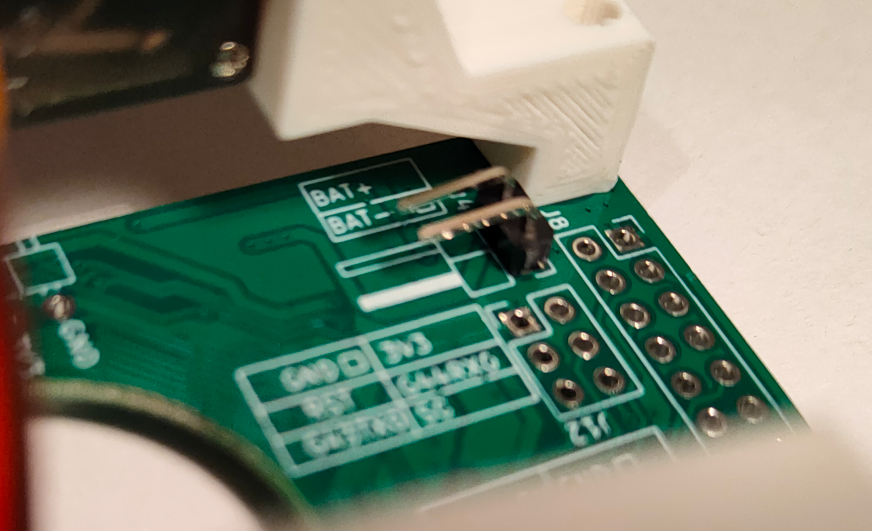
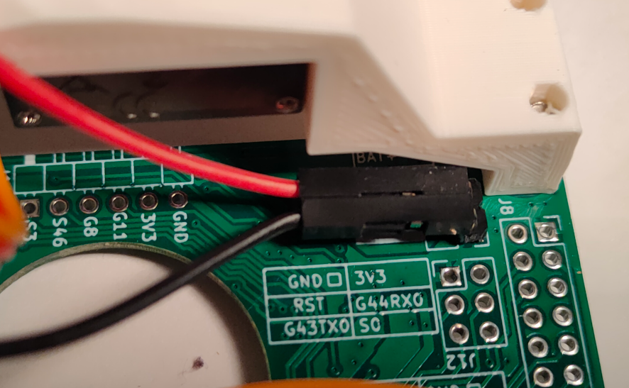
Connect positive wire from the Cell to BAT+ goldpin on the PCB, and the negative wire to BAT-. Polarity is described on a silkscreen next to the connector. After this step, press "POWER" button once, white LED (or LEDs, depending on the cell voltage) should come on. Press "POWER" button twice to turn it off. If the lights don't come on, make sure that the polarity is correct and that voltage is present at the end of jumper wires.
![]()
![]()
-
8Connect the servos to the PCB
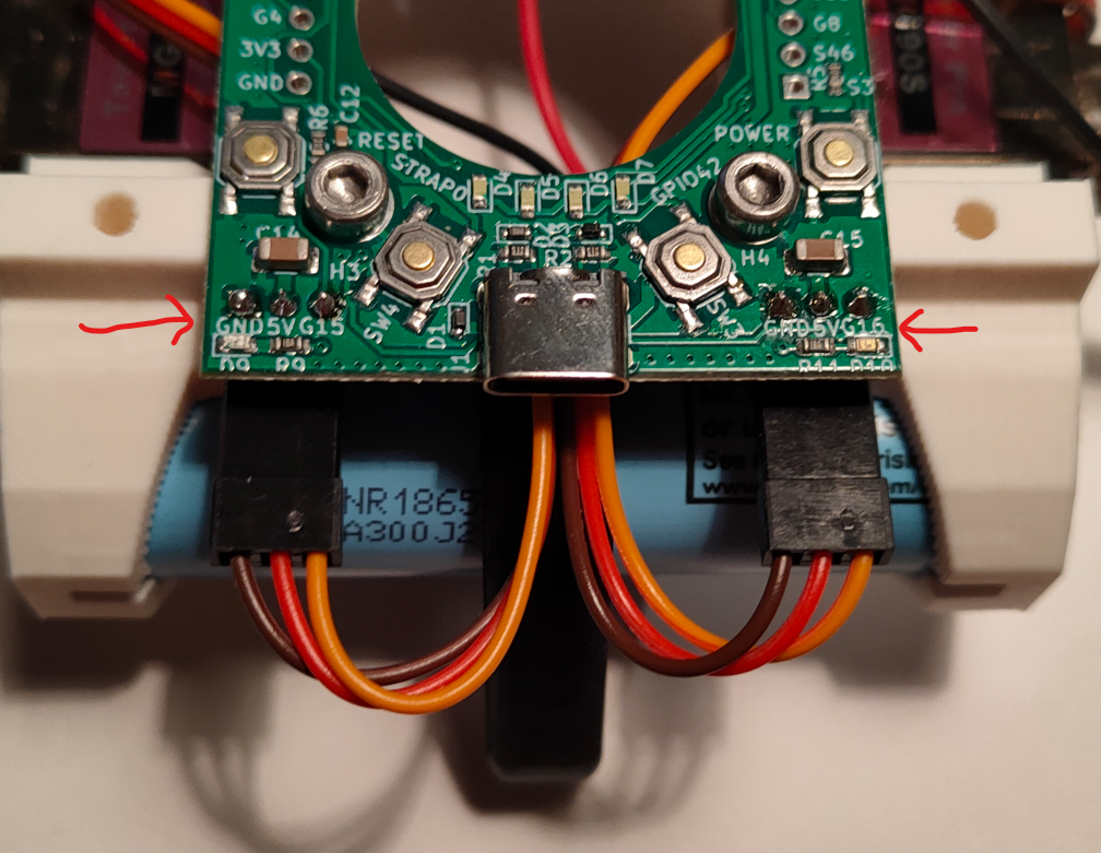
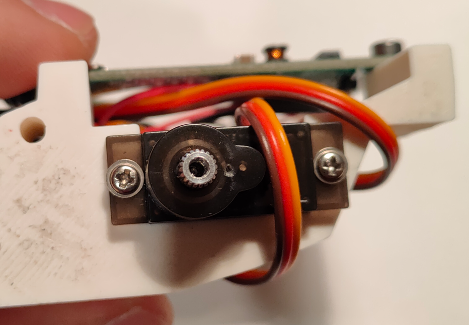
Connect servos to the PCB. Wires that comes with servos are very long, to achieve cleaner assembly it is advised to wrap servo wires two times around part of the chassis. Servos should be connected to three pin connectors that can be found on the rear side of the PCB, just above the cell. Connect left servo to left connector and right one accordingly. Brown wire is ground wire, you can find description on the PCB silk screen next to the three pin connectors.
![]()
-
9Wheel assembly
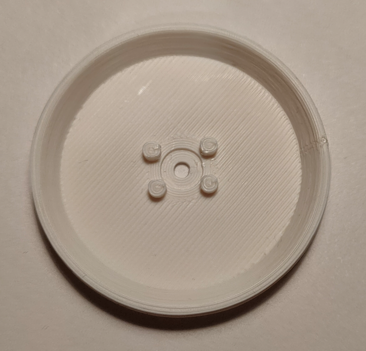
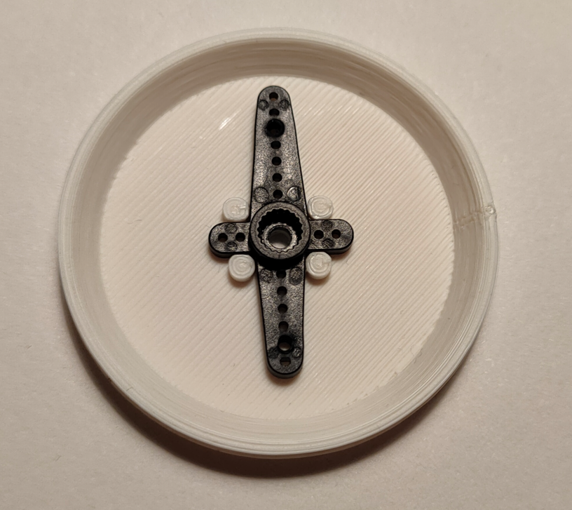
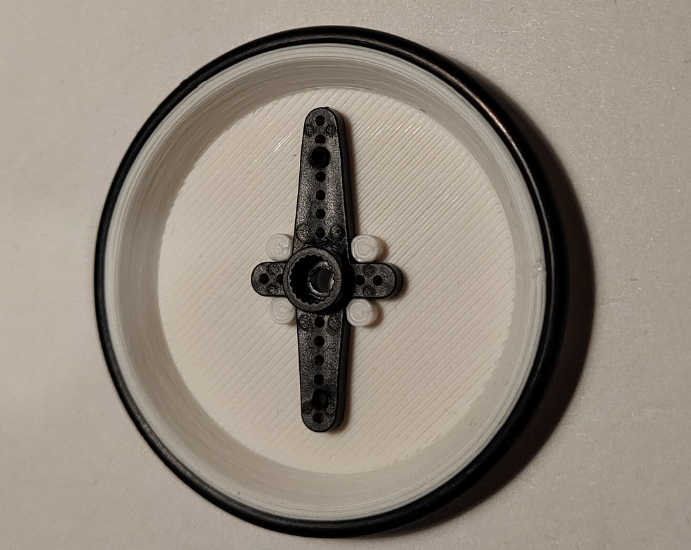
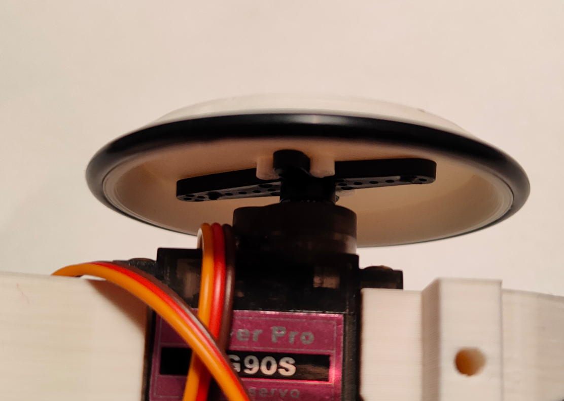
Put wheel with side that have four pins facing upwards on a flat surface. Press the servo arm with flange facing upwards between pins, there is only one correct position of the servo arm. Then put o-ring on the wheel like a tire.
![]()
![]()
![]()
-
10Mount the wheels
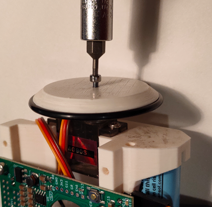
Press assembled wheels on servo shafts and secure them with M2x7 screws.
![]()
![]()
![]()
Kabot - lowering entry barrier to ROS2
Ultra low cost expendable platform connected to Robot Operating System 2, powered by micro-ROS
 Krzysztof Pochwała
Discussions
Become a Hackaday.io Member
Create an account to leave a comment. Already have an account? Log In.