Dan Julio
-
Version 1.1 always follows version 1.0...
10/07/2023 at 22:04 • 0 commentsI'm sure if I did a search I'd find an axiom that says something about version 1.0 of any software needing to be followed with another version. I shorted some testing in my rush to get the 1.0 firmware release out (because I was going to soon be busy with other projects) and of course it came back to bite me. Another weeBell user reached out because he was having echo problems and this started me looking at the code again in my off hours. Turns out that there were two problems, one of which was mine (more about the other one further down). I still hadn't gotten the audio code interface with the I2S driver so locked down that the delay between outgoing and incoming audio would always remain inside the bounds the OSLEC echo cancellation routines could handle.
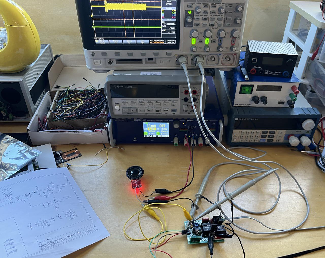
I also built an isolated telephone interface for two reasons. I wanted something that could output audio from phone calls I could record on my computer for an upcoming video I want to make about weeBell, and I also wanted something to feed a caller ID decoder using an ESP32 and spandsp for testing and for display of incoming numbers on my own Ooma VOIP landline.
![]()
This little gadget let me look at the Caller ID waveform - and compare it with the one generated by the Ooma. This lead to finding a few bugs related with Caller ID generation and race conditions with users picking up before it was transmitted or the call ending early. It, and more review of various standards, also led to a change in releasing the ring voltage between rings.
So a bit more testing and code changes later there is version 1.1 of the firmware (available in the repo or through the gCore Serial Programmer desktop software for easy updates).
The full release notes follow.
Bug Fixes
- Restructure audio_task and improve interface to I2S driver to ensure consistent synchronization between RX and TX paths so we can count on a static alignment of TX/RX data into OSLEC. Increase OSLEC tail to 32 mSec.
- Fixed a bug where the Caller ID transmission wasn't cancelled if the user picked early and it ran after call hung up.
- Fixed a bug where a race condition between picking up the phone after the first ring could re-trigger Caller ID transmission. Increased flush buffer to 50 mSec.
- Fixed a bug in the Caller ID logic where the final long ring of a cadence pair could re-trigger Caller ID transmission.
Functionality
- Slight mods to code so building with optimization turned on won't cause compiler warnings/errors.
- Detect more cases where the cellphone might route audio to weeBell outside of a phone call and have weeBell display the right state if the user picks up the phone.
- Modify ring waveform to return to normal levels between rings to match expected behavior.
- Set full volume output for Caller ID transmissions and Off-hook tones independent of volume setting.
- Set Caller ID Mark pre-amble bits correctly for Bellcore and European FSK (spandsp defaults were shorter).
- Modify bt_task so the local volume takes precedence over the volume sent by the phone when a call is established for outgoing calls.
- Modify screen dump to be triggered by power button (when compiled in).
Strange issue with older Motorola Android phone
The person who reached out was kind enough to do a bunch of experiments for me with his Android phones including collecting audio data for review. weeBell works perfectly with his Samsung phone but not his Motorola phone. The strange thing is that OSLEC doesn't seem to be effective when running with the Motorola phone even though the audio synchronization appears to be working and well within OSLECs echo cancellation tail. More experiments are in progress and hopefully we can get to the bottom of this. It may result in another release but I didn't want to hold this one up since it fixed some real issues.
-
weeBell Bluetooth firmware version 1.0 - with Caller ID!
09/16/2023 at 17:39 • 0 commentsI have finally fulfilled a goal I had since my original BluePOT project back in 2019 - to add Caller ID support. I know that it's not used by very old phones but I always felt it had to be there for me to claim my gadget was a good replica of a real phone system. Plus I wanted to learn how it was done.
Took longer than I thought it would
Actually, thanks to spandsp, adding Caller ID support itself wasn't that hard. A new state machine in pots_task and some new audio paths. I also had to add support for date and time as Caller ID sends this along with the phone number so I added a new GUI screen to set the time and some timekeeping utilities. Unfortunately it uncovered some confounding bugs as I would return to my desk in the morning to find the weeBell clock was massively slow. Turned out there were two bugs. One of which I fixed and one I am currently working around. The gCore RTC is used in a traditional HW RTC mode. It sets the time when weeBell boots. The system clock maintained by FreeRTOS is used as the operational time while weeBell runs. I found that both would be slow after a night where my cellphone was across the house and the Bluetooth connection between weeBell and the phone was very "iffy". At first I was confused why both would be slow but by different amounts. One of those situations where something confusing makes it hard to look in the right place to identify a problem. But after a bit I realized they were unconnected. Turns out the gCore RTC bug was because heavy I2C activity could cause it to miss once/second RTC interrupts. While weeBell runs it is constantly polling the gCore RTC/PMIC EFM8 micro-controller to see if the user has pressed the power button to turn the device off, as well as looking at battery and charge state for the GUI (and low battery shutdown). All of that polling was slowing down gCore's RTC. With some restructuring of the EFM8 code I was able to fix that bug (described here). However the system clock slowdown is still not entirely understood but I am pretty sure it has to do with the Espressif Bluetooth stack perhaps blocking timekeeping interrupts in the ESP32 under conditions where it is working excessively hard to initiate or maintain a Bluetooth connection. I am still debugging this (it is a slow process) but put in a work-around that seems to be ok. Every hour the gcore_task checks the HW RTC time against the system time and adjusts the system time if it finds the system time has drifted.
I also tuned up overall operation a little (the backlight fade-up and fade-down are much smoother now) and added a few countries (discussed below). All-in-all I'm really happy with this release.
Audio Architecture
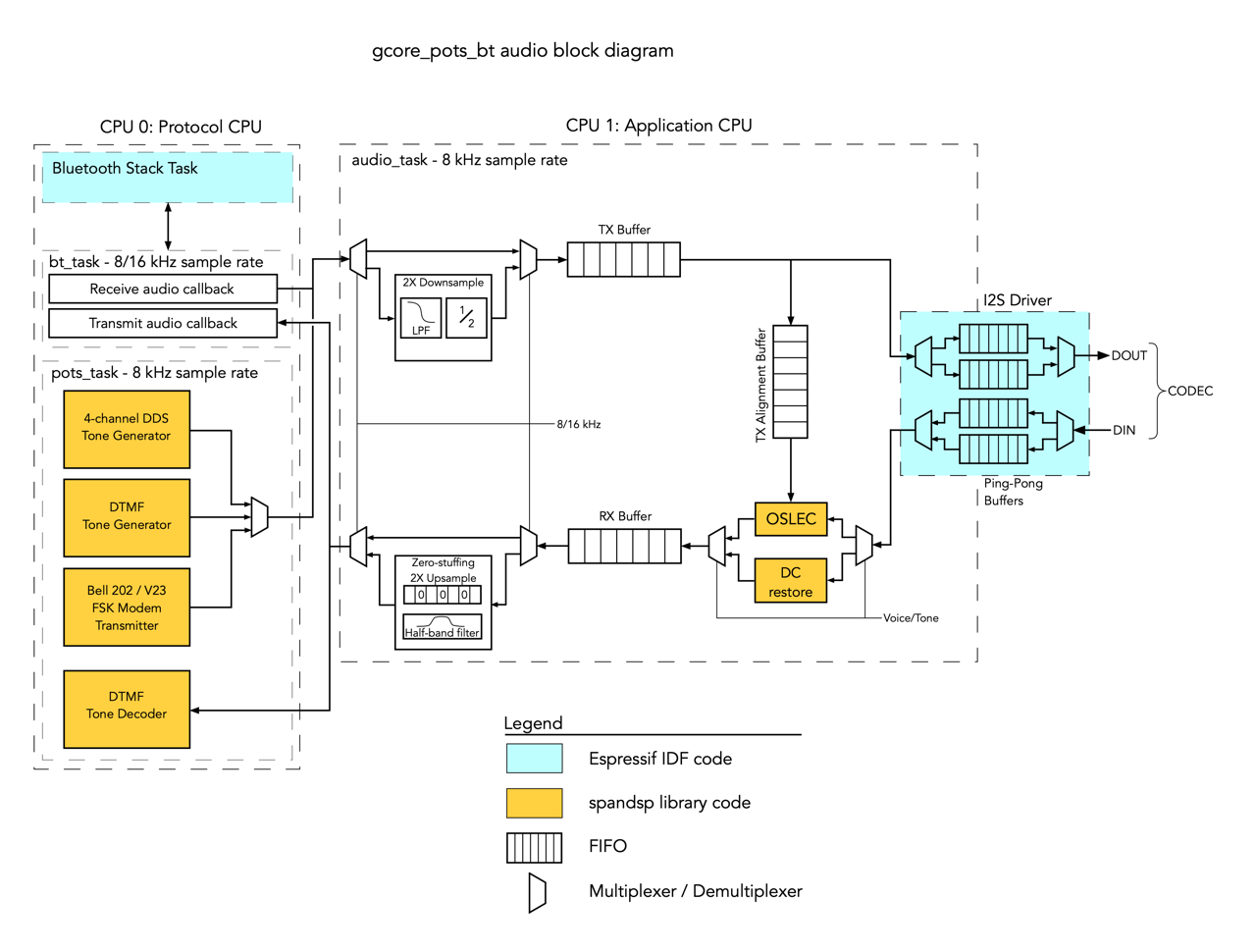
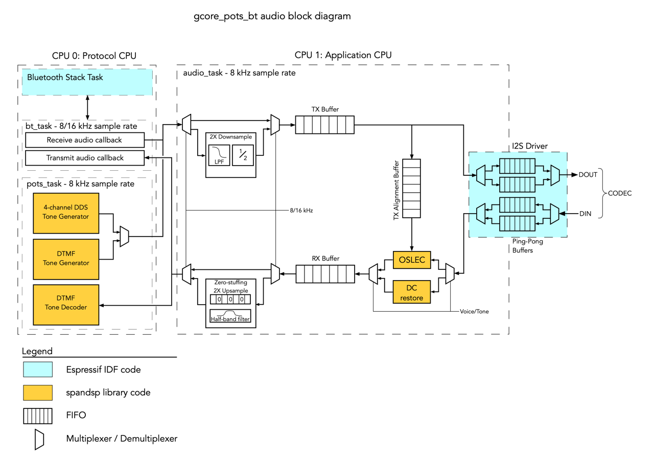
The primary addition to the audio subsystem is a FSK Modulator capable of either Bell 202 or V23 frequencies. This is essentially a 1200 baud modem implemented in software that is one way Caller ID is transmitted to the phone. The other way Caller ID is transmitted is using DTMF tones. The block diagram below shows the new audio architecture. In fact I have two DTMF encoders. The original is still used to generate DTMF during a phone call (for example a user of a rotary phone can type DTMF codes for '#" and '*" on the GUI to access a phone tree). The spandsp library also includes another DTMF generator in the Caller ID support functions.
![]()
GUI Changes
GUI changes were easy. Another control on the Settings screen takes you to a Set Time/Data screen. I copied most of the logic for the Set Time/Date screen from my own tCam firmware. I also copied over RTC and time support utilities from that project and modified them slightly for weeBell.
![]()
The time and date are also displayed on the main screen while it is connected to a cellphone.
![]()
The quick&dirty about Caller ID
Wikipedia informs us that Caller ID got its start in 1968 in Greece when an engineer named Theodore Paraskevakos began development of a system for a company working in the air transport industry. In 1971, working with Boeing he created the first practical system and demonstrated it to several telephone companies. He was followed by Japanese inventor Kazuo Hashimoto's 1976 prototype Caller ID display device. Although the phone companies initially wanted Caller ID to be a voice announcement (for which they would charge a per-call fee) another engineer, John Harris, working for Northern telecom argued it should be a feature of telephones and displayed instead of spoken. Ultimately the first commercial trial for Caller ID (plus some other services) was conducted in 1984 by BellSouth in Orlando, FL. It would take an additional decade for it to be rolled out across the USA.
In the USA the service eventually became known as the Bellcore Calling Number Delivery (CND) standard (TR-TSY-000030 and TR-TSY-000031) and is a based around transmission of information encoded using a Bell 202 modem (1200/2200 Hz FSK modulation) between the first and second rings. Initially the message only included a timestamp and the originating number (SDMF format). Over time additional message types were defined to include information such as the calling party's name (MDMF). Because the Espressif Bluetooth stack does not currently deliver the calling party name I only implement SDMF at this time.
Of course telephone companies around the world were also developing their own Caller ID systems and just like the early days of telephony there ended up being a whole bunch of protocols.
European systems used a V23 modem (1300/2100 Hz FSK modulation) instead of Bell 202. Some system used DTMF tones to transmit numeric data instead of FSK. Some systems would transmit the information before the first ring. In this case they used a variety of signaling mechanisms to indicate to the Caller ID receiver that a message was coming. They could reverse the line polarity and/or send a special 2130/2750 Hz dual-tone alerting tone (DT-AS). Some systems, like Ireland's, even sent a very short ring (RP-AS). The actual message formats varied between countries and there were at least four variants of DTMF encoding. In Japan the Caller ID system required the telephone to actually pick up the line for the Caller ID information then hang it up prior to the subsequent call.
Humorously the ETSI European Standards organization belatedly documented all the various methods in a document ETSI EN 300 659-1. Essentially it says, "here are all the ways it was done but we're writing it down now".
Currently I think weeBell can support most formats except the Japanese system. Unfortunately I don't yet have a way to test any system but the USA Bellcore system (I have an idea for a universal Caller ID box which I will work on if I find some time).
Supporting more Countries
One of the most fun aspects of all this for me is is getting to listen to the dial tone and rings of foreign countries. It's like a quick trip abroad. Supporting an international audience was a prime goal for weeBell.
To add support for a specific country I have to know the following things:
- Dial Tone
- Re-order (or Congestion) Tone
- Off-hook (or Howler) Tone
- Ring Frequency and Cadence
- Caller ID protocol
I have easily found Dial Tones although often a country would have many dial tones. I also can generally find the Re-order Tone. Finding Off-hook tones is much harder (or even if a country had one at all - in some countries it appears the dial tone just went quiet after a while). Mostly I work from a document I found in the spandsp library which presumably was used by Asterisk systems which lists tones by country. I also bought a short subscription to the 3amsystems website to look at their tone database (and download some of the tones I would implement using samples).
Finding Ring Frequency and Cadence is also problematic. Most online resources show the audio one gets in the receiver listening to a remote ring. This often, but not always, mimics what the real ringer sounded like. I did peruse youtube a bit finding various recordings of old phones ringing. And I found some European standards documents which listed the ring frequencies as part of test verification parameters.
But Caller ID information is the most difficult to find. This is because there was so much variation in things like the alerting phase as well as the fact that many countries supported multiple implementations (initially you had to buy a phone that matched your provider although eventually phones would support multiple standards). This is information I fear is being lost over time as well.
I spent countless hours researching but not always being sure of a specific country implementations. Ultimately I decided for version 1.0 of the Bluetooth firmware I would support a "representative" sample.
- Australia - For the interesting modulated dial tone.
- Europe - Call this "Typical" Europe. Most of Europe uses a 425 Hz dial tone and I think DT-AS Caller ID alerting before the first ring so this would be my test of that configuration.
- Germany Pre 1979 - When the dial tone was a Morse Code 'A'. And I'd test my code when configured for no Caller ID at all.
- India - Another country with a fun modulated dial tone and I could test Line Reversal alerting with one of the DTMF Caller ID protocols.
- New Zealand Rev - Supporting the reverse rotary dial phone (and testing my rotary dial map function).
- United States - Well, natch, my home country (plus we have a great Howler).
- United Kingdom - The Brits too have a great Howler plus they are the only place that uses one particular form of Caller ID (so called "SIN277" with Line Reversal + DT-AS alerting tone before the first ring).
It's pretty easy to add new countries to the firmware if you want to compile your own. You just add to the country_info data structure in the components/utility/international.c file (described in the international.h file). I'm also open to adding countries if anyone would like to reach out. I'll need the information above.
Firmware is here for anyone who cares.
-
The wide world of telephony
08/20/2023 at 19:47 • 0 commentsI am currently adding support for Caller ID and hopefully some more countries. This process has involved a humungous amount of online searches and, now fortunately, discovery of a few online groups of real telephone aficionados such as the Classic Rotary Phones forum, Telephone Collectors International and their forum and others. The problem is that a lot of information about telephone systems from around the world doesn't seem to have been documented in a searchable way online.
But this log entry isn't about my troubles. It's to share some fun things I found along the way.
AT&T had to teach Americans how to use a Dial Telephone
The first dial telephones were manufactured in 1897 but Bell didn't start rolling them out until 1919. Unbelievably, it took until 1978 for the entire United States to receive dialing capability!
Here's a short video of a newsreel shown in movie theaters the week before a town or region would be switched over to dialing.
And a longer video about a fictional town being taught how to dial (skip to 5:30 to get going or start at the beginning to realize how much shorter our attention spans have become).
Odd Rotary Dials
Most of the world used the same rotary dial layout that starts with the digit "1" (generating 1 pulse) and ends with the digit "0" (generating 10 pulses).
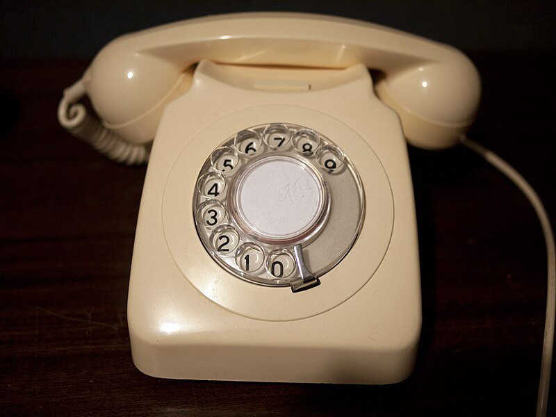
New Zealand used that standard format but also had a reversed format starting with the digit "9" (generating 1 pulse) and ending with the digit "0" (generating 10 pulses).
![]()
(courtesy Nition1 under the Creative Commons license)
And in Sweden the phones started with the digit "0" (generating 1 pulse) and ended with the digit "9" (generating 10 pulses). The engineers who were implementing the first Swedish telephone network must have thought the rest of the world crazy with their out-of-sequence dials.
![]()
(courtesy Holger.Eligaard under the Creative Commons license)
weeBell handles these different dial layouts using a mapping structure that is part of the international.c file entry for each country. For New Zealand I will have two entries "New Zealand" and "New Zealand Reverse".
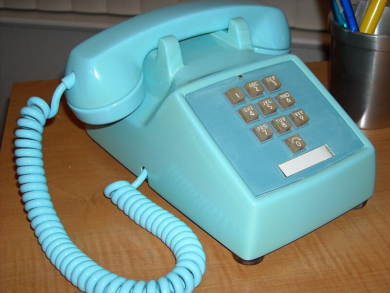
The first DTMF phones
Here in the USA the announcement of Touch Tone dialing was made at the Seattle World's fair in 1962. A new Western Electric 1500-series phone was introduced and became available in 1963 (source). The interesting thing is that it only had ten buttons. The * and # keys we all know today weren't added until 1968 with the 2500 series.
![]()
Paul-F's website has a very interesting discussion of Touch Tone development. There was a lot of what we now call User Experience (UX) testing before Bell Laboratories settled on the ubiquitous keypad layout that still appears on our cell phones today.
![]()
(Source: Bell System Technical Journal, July 1960, p. 999
"Human Factors Engineering Studies of the Design and Use of
Pushbutton Telephone Sets," by R. L. DEININGER)As most of us know, the DTMF tones are comprised of two frequencies (row and column). weeBell generates them in software using a DDS synthesizer (essentially a sine wave table lookup, scaling and mixer). Lots of transistors involved in that (but they're cheap). I couldn't find a schematic for the 1500 series but the 2500 series keypad uses a single transistor along with a tapped coil to generate both frequencies. A less known fact about DTMF tone generation is that an additional four keys are specified - 'A' - 'D' - which were typically used for network control although they made an appearance on some military phones and are still used by Amateur Radio operators for remote system control today.
A Morse Code Dial Tone?
You bet. Up until 1979 the German telephone system used pair of 475 Hz tones, the first 200 mSec long, and the second 700 mSec long separated by 300 and 800 mSec gaps. This is morse code for the letter 'A'. You can hear it here. After 1979 they changed to a continuous 475 Hz tone.
Enough for now
I hope you enjoyed reading this. My next log will talk about the different Caller ID mechanisms used around the world.
-
Audio Architecture
07/31/2023 at 18:13 • 0 commentsThe most interesting part, for me, of the Bluetooth Handsfree firmware for weeBell has been the audio subsystem. I've never really done real time audio before (aside from generating tones or using a library with a I2S DAC) so it was a good learning experience. Aside from the hard real-time nature of audio, there were several technical challenges to overcome.
Perhaps the most difficult technical challenge was Line Echo Cancellation. All POTS telephone interfaces multiplex received and transmitted audio onto the same two wires going to the telephone. Traditionally this was done by a circuit called a Hybrid which consisted of a set of coils or transformers. For weeBell, it's done by the AG1171 with active circuitry. One of the characteristics of the hybrid is that it echos back received audio due to impedance mismatches. In a system that has hundreds of milliseconds of delay, such as a long distance line or a cellular connection, this causes the remote talker to hear their voice echoed back to them and is unpleasant. The introduction of long distance calling required the telephone companies to find ways to cancel that echo through Line Echo Cancellation (or Echo Suppression in the early days) where the received signal is subtracted from the echoed signal in the transmit path before being sent back into the network. Here's a paper that discusses the echo canceller Bell Labs developed when sending telephone calls through the Telstar satellite.
![]()
(picture from David Rowe's blog)
I was initially concerned about how I would perform this function but fortunately we live in the glorious time of searches and code repositories. This problem - and others - has been solved many times and I found David Rowe's amazing OSLEC (Open Source Line Echo Cancellation) code along with a bunch of telephony functions in Steve Underwood's wonderful spandsp library which was archived from SVN to github. Originally written for Asterisk this C code is incredibly well written and easy to use.
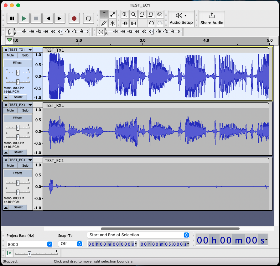
My code includes the ability to store the audio samples surrounding the OSLEC routine to gCore's Micro-SD card and I used that a lot while developing the code. The following image shows OSLEC in action with the samples displayed in Audacity. The TX audio path is from the remote speaker intended to be heard in the handset. The RX audio path shows the echoed signal from the hybrid before echo cancellation. And the EC audio path shows the signal from the hybrid after echo cancellation as it is returned to the remote talker. You can see OSLEC has a very short "training" period and then is very effective in removing the signal. There's lots more to it and you can read about OSLEC's development on David's blog starting with this entry.
![]()
The spandsp library also provides DDS tone synthesis (including DTMF tone generation) and a goertzel based DTMF tone decoder that I press into service as well. In the future I want to use the modem functionality in the library to generate caller ID information.
The overall audio architecture is shown below.
![]()
The real-time audio subsystem is contained in the audio_task that has CPU 1 all to itself. It runs with a 8 kHz sampling rate since that's what spandsp was designed around. In addition to the functionality provided by spandsp the audio subsystem also has to convert the 16 kHz sampling rate the Bluetooth Handsfree audio connection can use if both the cellphone and remote device support the MSBC codec.
Both downsampling from 16kHz to 8 kHz and upsampling from 8 kHz to 16 kHz are slightly more complicated that just halving or doubling the data because of the frequency aliasing and non-linear distortion.
Downsampling is very simple and compute efficient. Each two samples are averaged as a simple low pass filter and generate an output rate of half.
Upsampling is slightly more complex and uses a buffer where the incoming stream is stored in every other entry and the entries in-between start off with zero. Then a band-pass filter is run over the buffer and the result is a clean 16 kHz sampled buffer.
One final note. When Steve and David were writing spandsp and OSLEC in the early 2000s they targeted either a [then] high-end Intel x86 CPU with MMX or SSE2 extensions or a specialized Blackfin DSP with optimized code. They also have straight C code which presumably was used during development but the specialized code was used by actual production systems. In 2023 the inexpensive ESP32 is capable of running the straight C code with plenty of spare cycles. What fun! I definitely encourage you to check out their work.
-
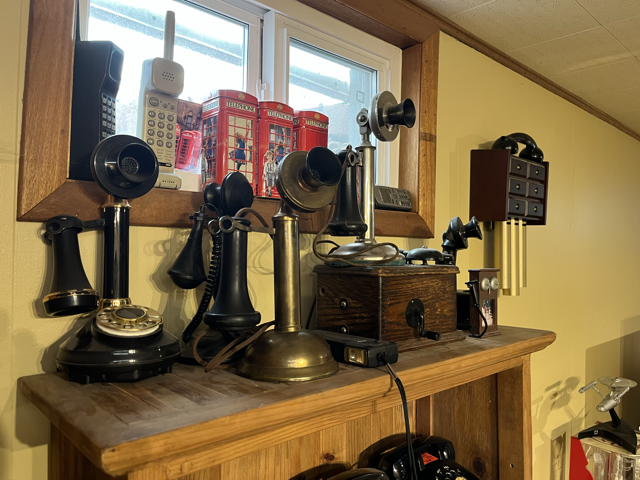
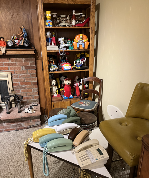
Testing with the mother-load of POTS phones
07/09/2023 at 17:55 • 0 commentsI spent a recent morning at the home of my friend (and great electrician) Randy P who is a telephone collector. It wasn't until years after we met I learned of his hobby and he was someone I had in mind as I designed weeBell. He graciously offered his collection and time to test weeBell_bluetooth with a bunch of different phones.
![]()
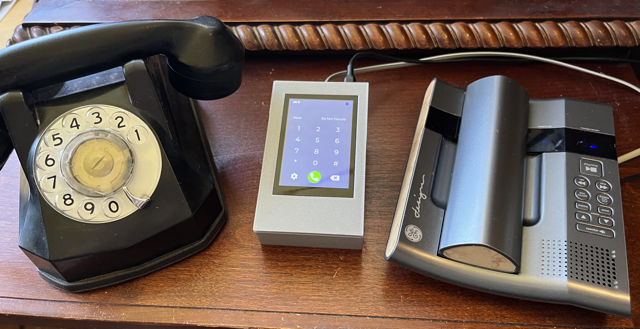
We setup on his kitchen table and both placed and received calls with different rotary dial and DTMF phones.
![]()
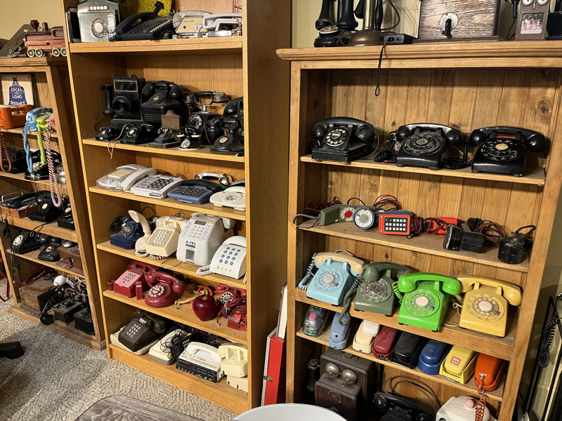
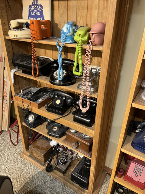
We had a huge inventory to choose from:
![]()
![]()
![]()
![]()
And I'm not even showing the Star Trek phones...
Sadly I didn't think to bring some extra wiring supplies so phones that used the very old 4-prong connector couldn't be tested. Another day for that I hope.
![]()
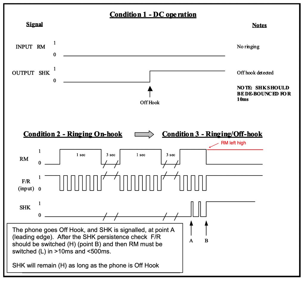
Testing went well including the discovery of a firmware bug. One of the rotary phones dialed incorrectly (dialing a 2 returned 1, dialing 1 returned no number at all). But this only malfunctioned after the phone had rung for an incoming call. I brought the phone back home with me and connected the GPIO signals to/from the AG1171 to my scope. The problem was immediately obvious. There is a signal to the AG1171 called RM which is driven high when you want to initiate ringing (another signal, F/R, toggles to actually ring the bell). My code was leaving RM high as shown in following image taken from the AG1171 datasheet.
![]()
For some reason, that I didn't puzzle through, the phone does not register the first switch closure as the rotary dial moves after dialing. The bug was a slightly embarrassing one line fix. I have a subroutine which is supposed to be called at the end of a ring. It both sets the state of the software ring state machine and the correct GPIO outputs for RM and F/R. However my code was simply setting the state instead of calling the routine. Changing the direct setting of the state variable to a subroutine call fixed the problem.
Looking at Randy's collection was a lot of fun. A couple of phones were really interesting as they show the features we use today were explored a long time ago.
Multi-line phones first made an appearance in the 1930s.
![]()
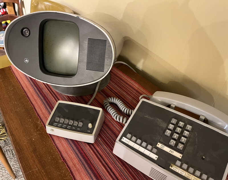
And the video phone in the 1960s.
![]()
Sure would be fun to try to make that work again but Randy looked slightly askew at me when I suggested it... :-)
I'm giving Randy a weeBell and he said he plans to use it in his truck and on job sites with different old phones. He's sure it'll turn a lot of heads.
-
Boards up on tindie
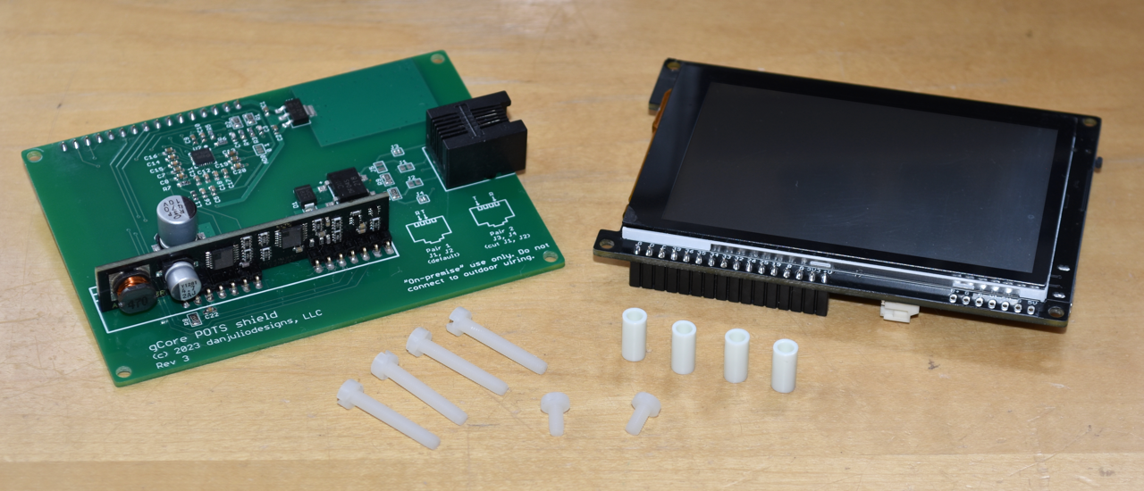
07/03/2023 at 18:34 • 0 commentsTindie approved the store entry for the ten boards I built. I also put together a kit with a gCorewith header pre-soldered (and weeBell_bluetooth preloaded) and mounting hardware.
![]()
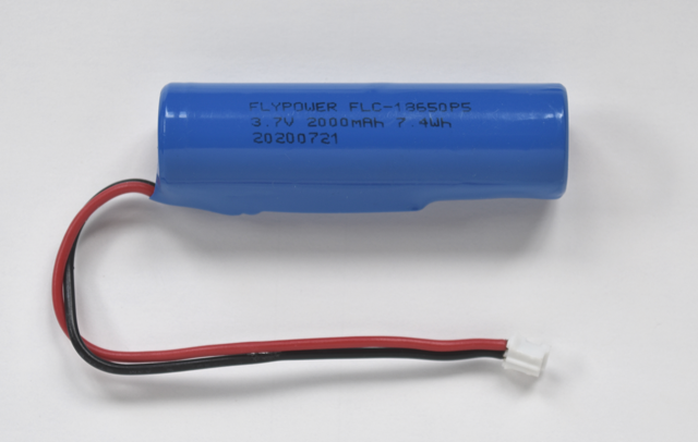
You'll need a 18650 LiPo battery to fit in the 3D printed enclosure as well. Adafruit has an battery with the correct JST cable already connected (you can also buy it from Digi-Key). Or you could make your own by soldering or spot welding a JST cable assembly to an existing cell (I know people don't like to solder to battery terminals but I've never had a problem). Just make sure the 2-pin JST PH connector has the Sparkfun/Adafruit polarity.
![]()
-
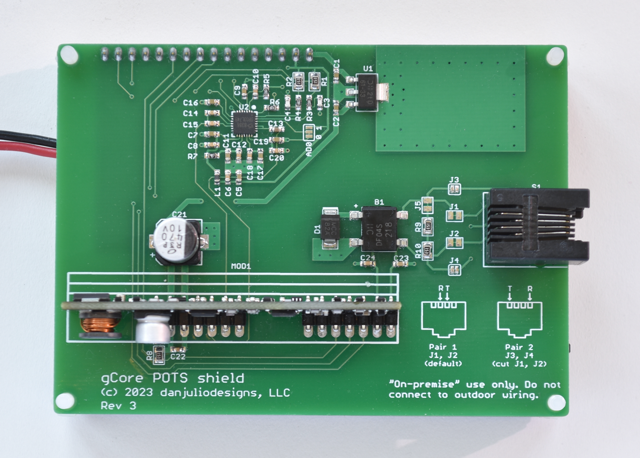
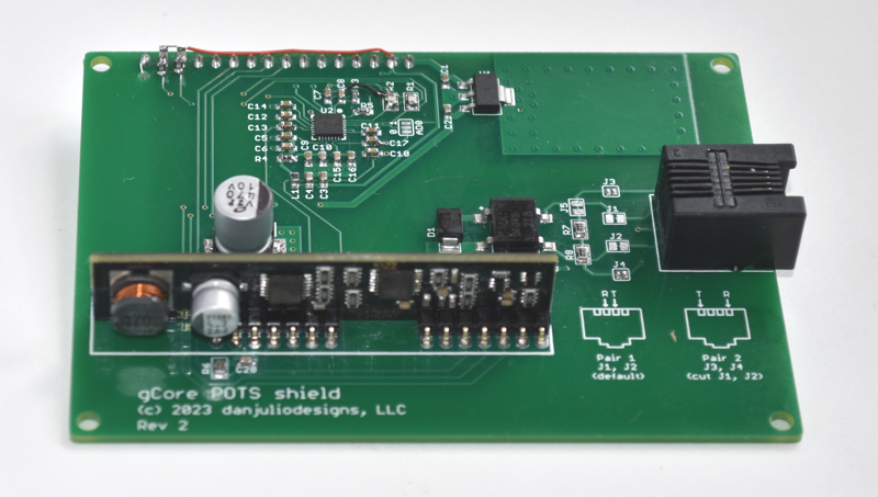
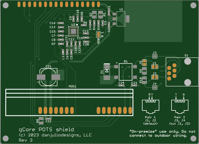
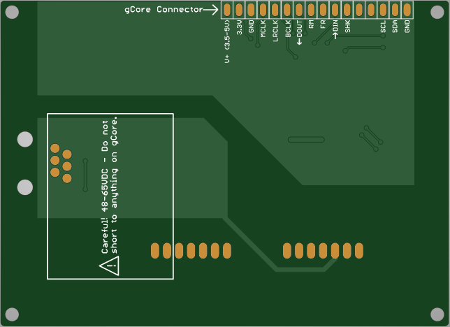
Rev 3 board qualified and a few built
07/01/2023 at 17:32 • 0 commentsThe integrated I2C filter on the Rev 3 boards works and I built up a small set of boards to try to sell on tindie to see if people would be interested in buying weeBell kits.
![]()
Old bug found and fixed
Some of my original Teensy code that handled the AG1171 ringing control made its way into the ESP32 code-base. I used two phones to test the Rev 3 boards I had built to make sure all functions worked.
![]()
During testing I noticed that the rotary phone bell would ring but the more modern DECT wireless phone would not. This made me worry that I had a hardware issue of some kind (not a great feeling after hand building 10 boards). Connecting the scope to the tip and ring signals showed reasonable voltages during ringing (not what central offices used to generate but close to what the AG1171 spec claimed it would generate). I was puzzled, until I told the scope to do a set of measurements to get the RMS voltage and it also told me the frequency was 10 Hz. Oh snap. I hadn't even noticed the timescale. My code was generating a ringing frequency half of what it should have been (USA has 20 Hz ringing frequency). Simple code fix. But what was funny is that in all the years playing with this stuff (from Teensy days through weeBell) I had never recognized that when the phone rang it was way too slow of a ring. But instantly my brain recognized the fixed ring as the way it should sound.
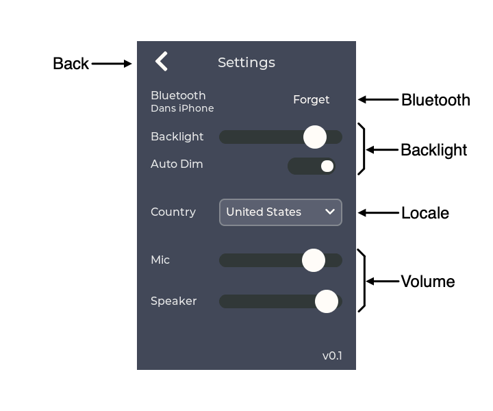
Also slight GUI mods
I made a small change to the background of the slider and slide-switch widgets so they show up better on the settings page.
![]()
![]()
Version 0.2 firmware will be pushed shortly.
-
Initial projects pushed to github
06/27/2023 at 21:34 • 0 commentsMy vision is that the weeBell system can have several different applications, each with different firmware. So to this end I am creating repos for each of the applications and another for hardware documentation.
- Hardware documentation can be found at weeBell_hardware
- The bluetooth application for weeBell can be found at weeBell_bluetooth
All code is GPLv3.
I've also built up about 10 gCore POTS shield boards and as soon as I test them I'll add them for sale on my tindie storefront.
Still trying to coordinate with my friend who has a huge telephone collection to test with. I suspect there are still some issues with audio processing.
-
Third time's the charm (he says hopefully)
05/29/2023 at 15:16 • 3 commentsOh I2C...you difficult child, you
I received the Rev 2 boards and ES8388 codec chips last week and got a board built up. It took a day more to finish the codec driver port and then I could start debugging. After working through the initial compile errors, I was immediately greeted by I2C errors communicating with the ES8388. Lots of them. Sometimes the chip simply wouldn't respond and other times it would respond to an address but not let go of SDA at the end of a cycle leading to a timeout. At least it wasn't f*cking up transactions to the other chips like the SGTL5000 did but I was seriously bummed.
Scope traces looked fine but clearly something was wrong. Things got slightly better when I removed the second set of pull-ups on the board (leaving only gCore's 10k pull-ups). I could at least get through the codec initialization sometimes. Then I would see failures when I2S was running (2.048 MHz MCLK) and the chip was accessed to change volume (but no errors when I2S wasn't running). I could see some apparently slight indications of cross-talk, but at least on my 200 MHz BW scope, they didn't appear to violate the VIH and VIL levels in the ES8388 spec sheet. Perhaps, though, the ES8388 was seeing some ultra-fast glitches as additional clock pulses.
Should have followed through with more research
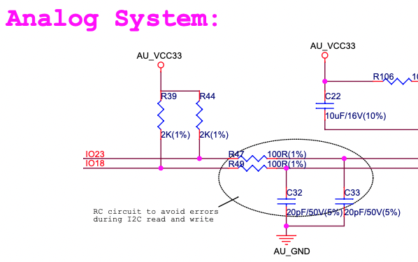
Then I remembered seeing something on the schematic for the AI-Thinker A1S ESP32 module which has the ES8388 built-in (I used their dev board to play around with the HF demos originally).
![]()
There is what looks like an RC filter on the I2C signals going to the ES8388. I originally dismissed this circuit when I laid out my board thinking the designers must have been over cautious but in the light of my own failures I had the realization that circuit was probably there for a reason. Doh'
Some quick digging turned up Espressif's Lyra T dev board schematic complete with a note...
![]()
Oh crap. I shouldn't have been so quick to dismiss what I'd seen.
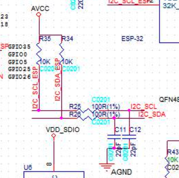
A quick hack later and my board had a similar filter on the I2C lines.
![]()
Look at the top left corner of the image. You can see 2 15k pull-ups tombstone style and 100 ohm resistors soldered to the cut traces. 22 pF caps are where R1 and R2 used to go completing the filter.
It worked. I2C errors were now a thing of the past. So a note to anyone thinking of using the ES8388 ... remember to include a filter!
I could now finish debugging the ES8388 driver which mostly meant adjusting various gains so the audio sounded right although I included a bit of black magic I found in the Espressif ADF driver that accesses undocumented registers with the comment that it's to make 8 kHz sampling work (which is what I use).
One more round of boards
Let's hope the third time's the charm. At least the modified Rev 2 board seems fully functional and I am planning to take my proto to visit a friend who collects antique phones for an afternoon of calls making sure this works with a variety of phones.
![]()
![]()
R1-R4, C1, C2 are the I2C pull-ups and filter. Rev 3 also got some more warnings and notes.
-
Bluetooth tamed (with a compromise and a surprise)
05/27/2023 at 19:38 • 0 commentsLots of code changes later, I'm finally happy with the state of things - at least on iPhone - I have yet to test with an Android phone. The device is able to reliably reconnect when a phone comes back in range and other functionality seems stable. And it seems to handle all the possible situations with audio routing and various bluetooth low-level notification traffic.
Fast Support from Espressif
I found a bug in the Espressif low-level (binary blob) Bluetooth library that would crash the app (StoreProhibited) if the phone was at the edge of Bluetooth range. At night I sleep with the phone on a nightstand across the house from my lab. I leave weeBell running and logging output and in the morning I noticed it would crash and reboot many times overnight. Sometimes with a cryptic error from the low level code. I dove into the Bluedroid library port but was soon stymied by the lack of source for this library so I posted a bug report on Espressif's IDF repo late one night. Much to my surprise there was a response the next morning from an engineer saying to try a version of the library they had published two months prior (I thought I was up-to-date but I wasn't). Boom! That fixed it. The engineer then checked back with me a couple of days later to see how I was doing. I was really impressed.
A compromise in security
I hope to be able to use the modern Bluetooth Secure Simple Pairing (SSP) mechanism to pair weeBell with a phone. Although in reality this gadget probably doesn't need to be incredibly concerned with security I wanted experience with this part of the specification and the Espressif implementation supports it.
The old PIN method of pairing devices is insecure. It can be snooped and has the potential for a man-in-the-middle attack. SSP uses cryptographic means to protect both sides and has several mechanisms for user confirmation as well. My implementation displays a 6-digit code on the GUI in a pop-up dialog box and the same 6-digit code should be displayed on the cellphone during pairing. The user confirms both match and the pairing is completed.
Only the iPhone displays a dialog box asking if you want to share your address book instead of the 6-digit code. So the pairing can't be confirmed back to weeBell (although the iPhone thinks it has successfully paired!).
![]()
What is interesting is that the pairing process creates a bonding record in the ESP32 NV storage (where it stores remote devices MAC addresses, keys and the like) even though my code never got the callback indicating authentication had been successful. Before I updated to the new low-level library I would get a callback indicating the iPhone wished to pair around a minute later and both my code and the iPhone would display the dialog boxes with the code and they could complete the pairing. However after I updated the low-level library this no longer occurred so there was no way to pair with my iPhone.
Long story short, I ended up - at least for now - falling back to the older PIN style of pairing and that works. At least I don't use the pins 0000 or 1234 - and my device only advertises itself for discovery during the 30 second max pairing window when the user presses Pair.
Hopefully over time this can be figured out.
The current ESP32 Bluedroid implementation does not support the PBA or PBAP (phone book) profiles. These are what your car uses, for example, to display the name of who is calling and to let you access your phone's address book from the car's touchscreen. I submitted a feature request so hopefully Espressif will support this someday and then I'll add support for it in the GUI. But it's still strange the iPhone displayed this message when the device it's connecting too doesn't support it. I wonder if either Apple simply assumes any HFP device will support PBAP or if the ESP32 is advertising something it doesn't do (I looked very hard through their code and saw no indication it does). Apple should still be displaying the 6-digit code first though.
And speaking of iOS strangeness
As you might imagine I have placed a lot of calls to myself (between my weeBell/cellphone and my VOIP landline). I also place a lot of bogus calls to test various edge conditions. Dialing gets tedious so I started to place single digit bad calls. The iPhone does not like this! And displays the most un-Apple-like error message after a spinner runs for a minute or so:
![]()
If I was a security guy I'd definitely experiment with initiating invalid HFP calls from a Bluetooth device to see if that could open any interesting doors... But I'm not, and time is short, so I'll just leave this here for your amusement.
New Boards Back
Next post will describe the adventures in bringing up the Rev 2 board. I officially hate I2C...
weeBell - personal central office for POTS phones
weeBell brings the goodness of old telephones into the modern age in a portable package that speaks GUI, Bluetooth and Wifi