Key features of this project
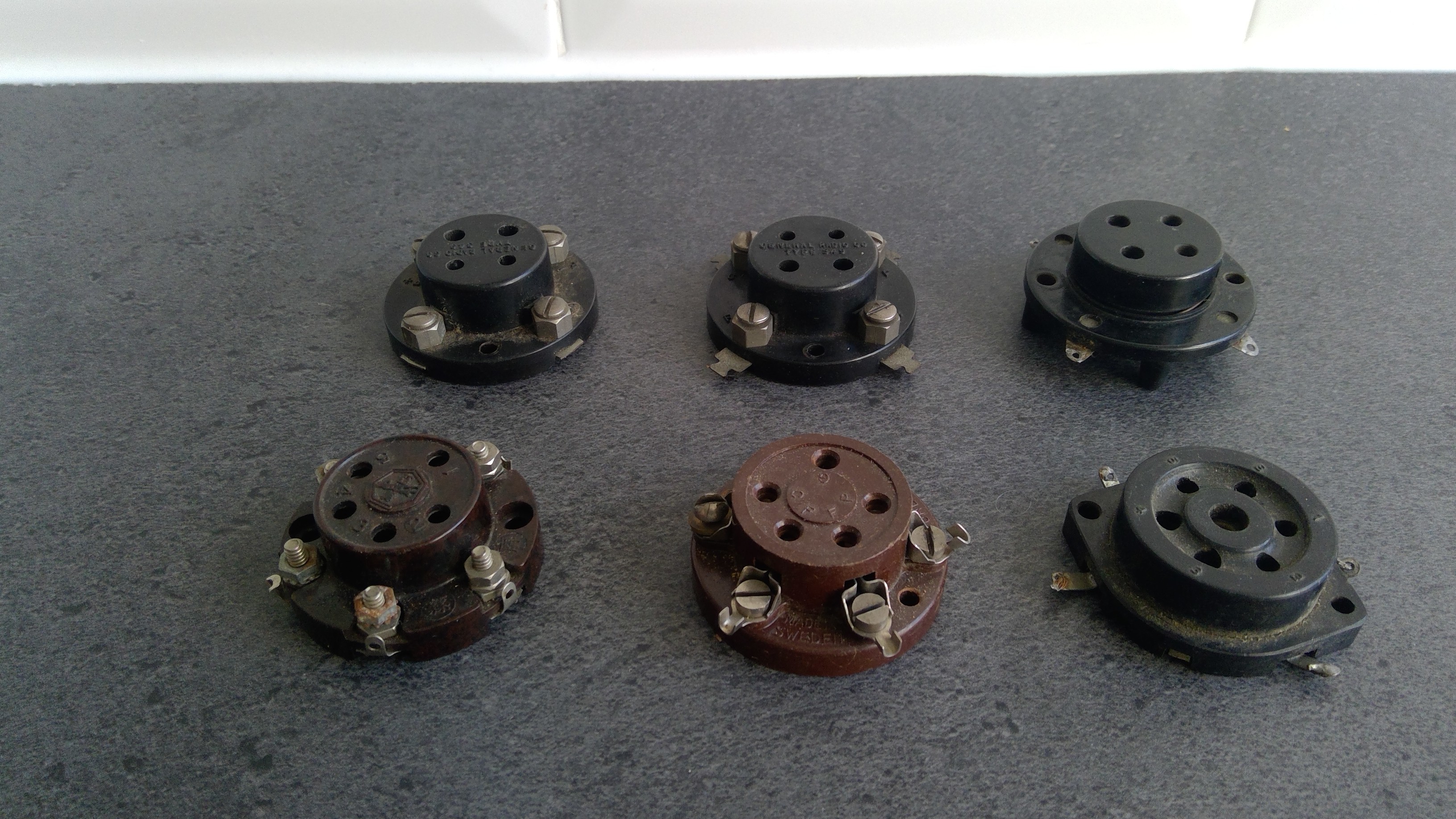
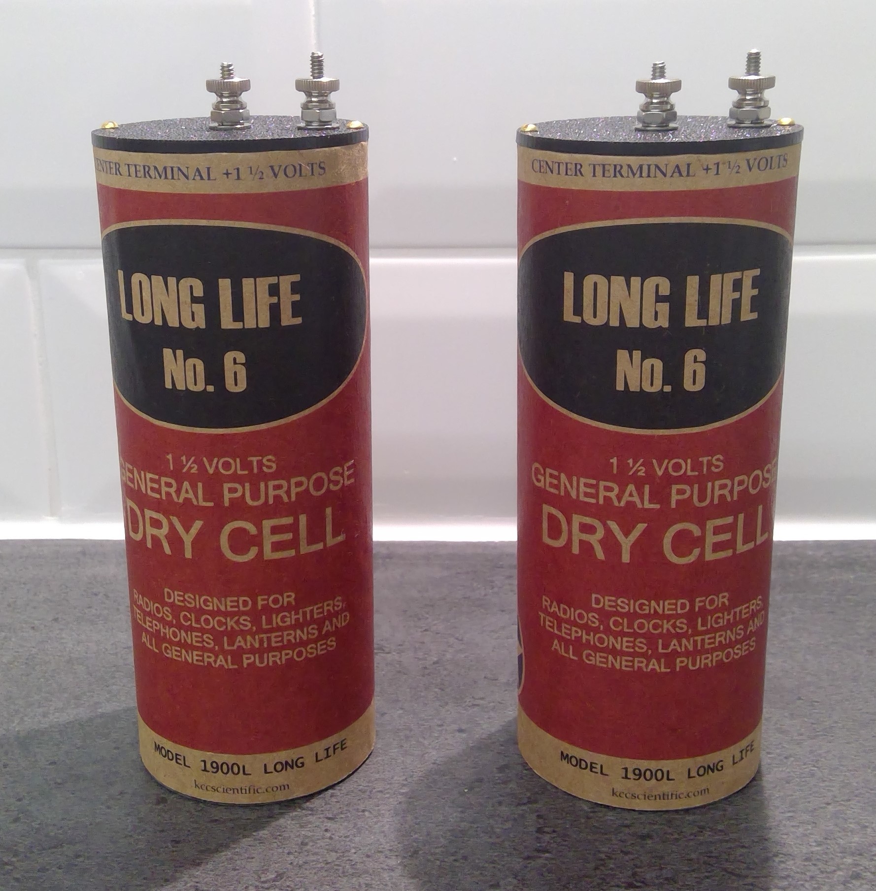
- Use "old style" electronics. These can be original electronic components (sometimes known as "NOS" or New Old Stock), or could be modern reproductions of old components. It can also include hand-made components that date from the time. A radio experimenter from the 1920's could wind a coil (inductor) so we can do the same.
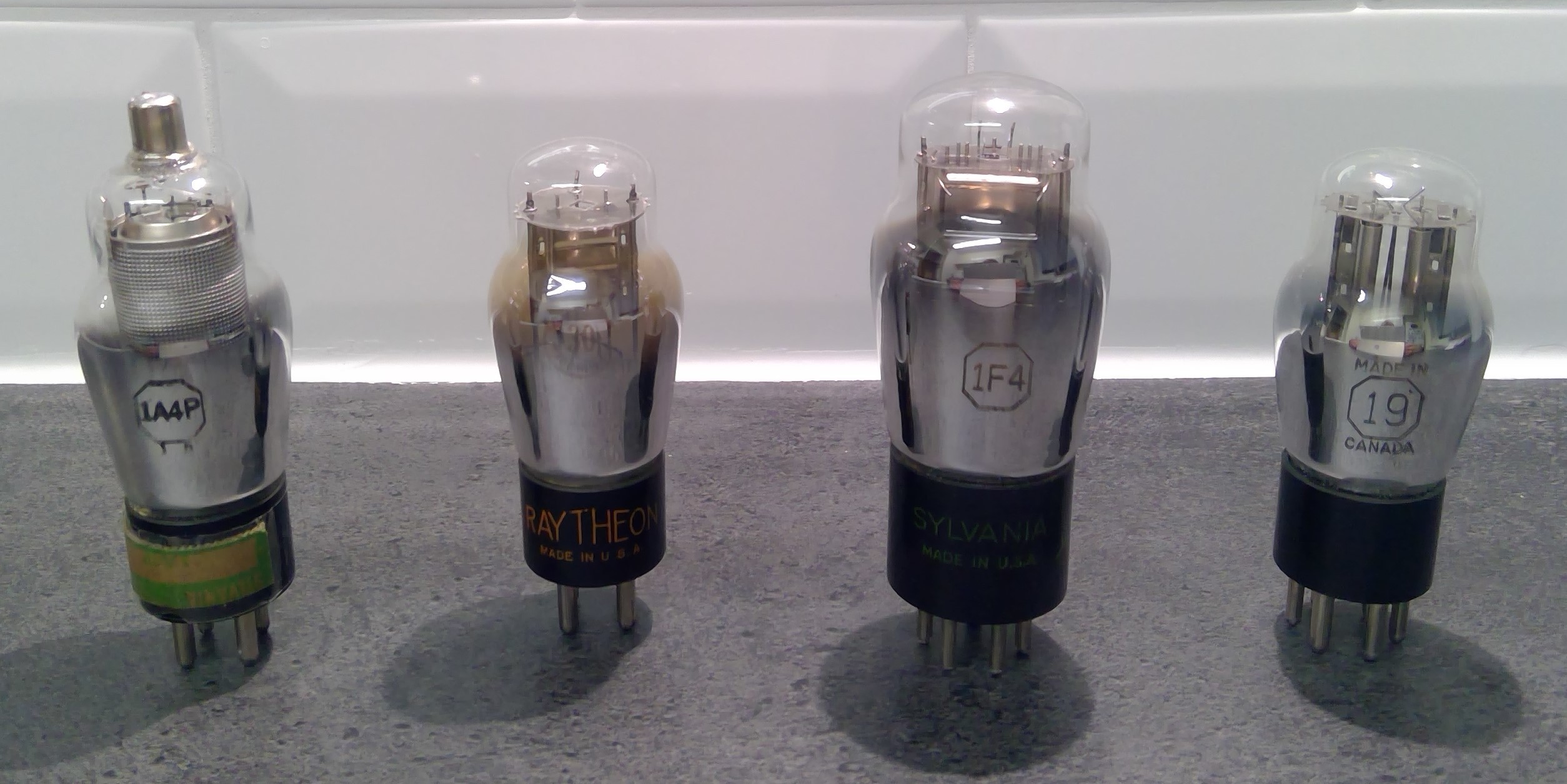
- It should look artistic in a technical kind of way. Polished wood, shiny valves, brass terminals, and unusual looking components should all feature. The wiring should not look complicated and there should be no "rats nests" of wires.
- Parts should be available. I can't promise parts will be cheap or easy to find - but it should be possible to make, adapt or buy all the parts from somewhere.
- It should not need advanced skills to build, nor should it need metal working skills. It should be buildable using hand tools, a basic knowledge of electronics and a multi-meter.
- The radio receiver should be portable. It will be in a self contained case with batteries, a loudspeaker and a handle.
- It should work on long waves, medium waves and possibly short waves.
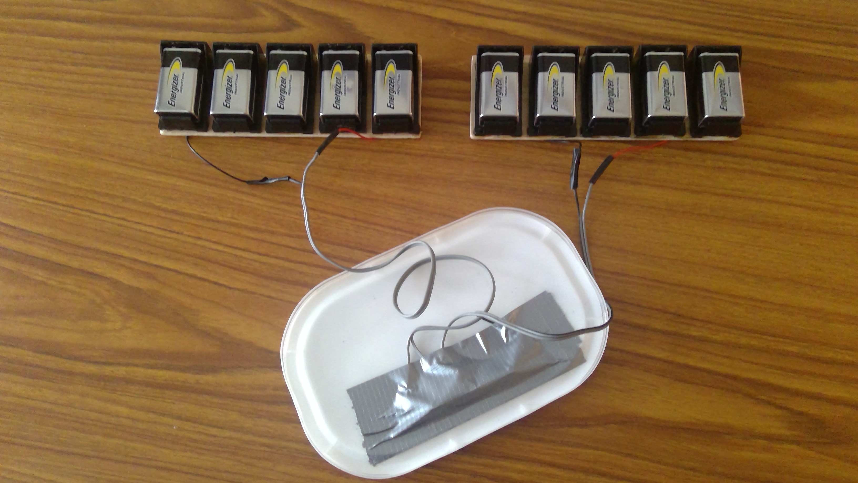
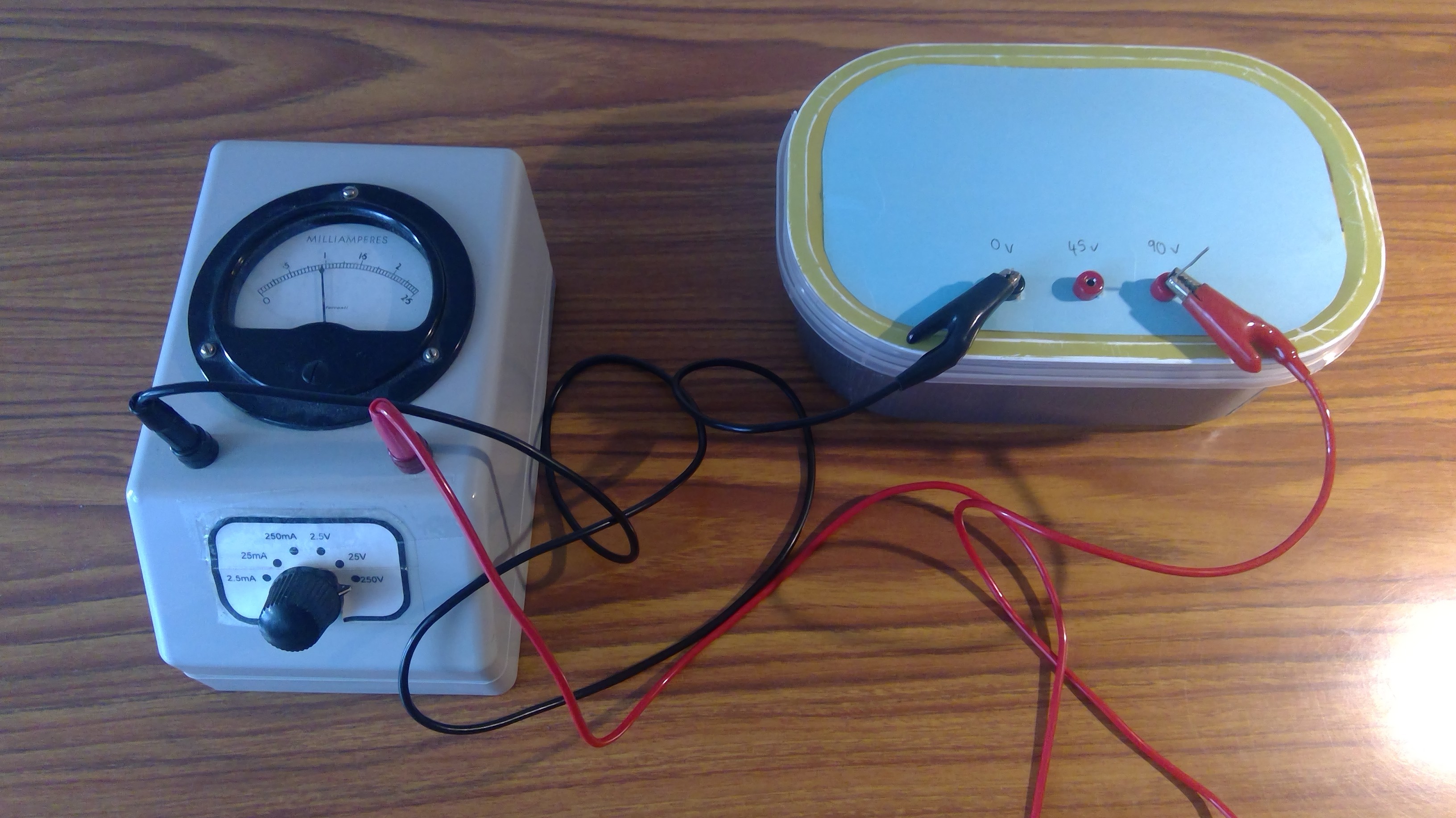
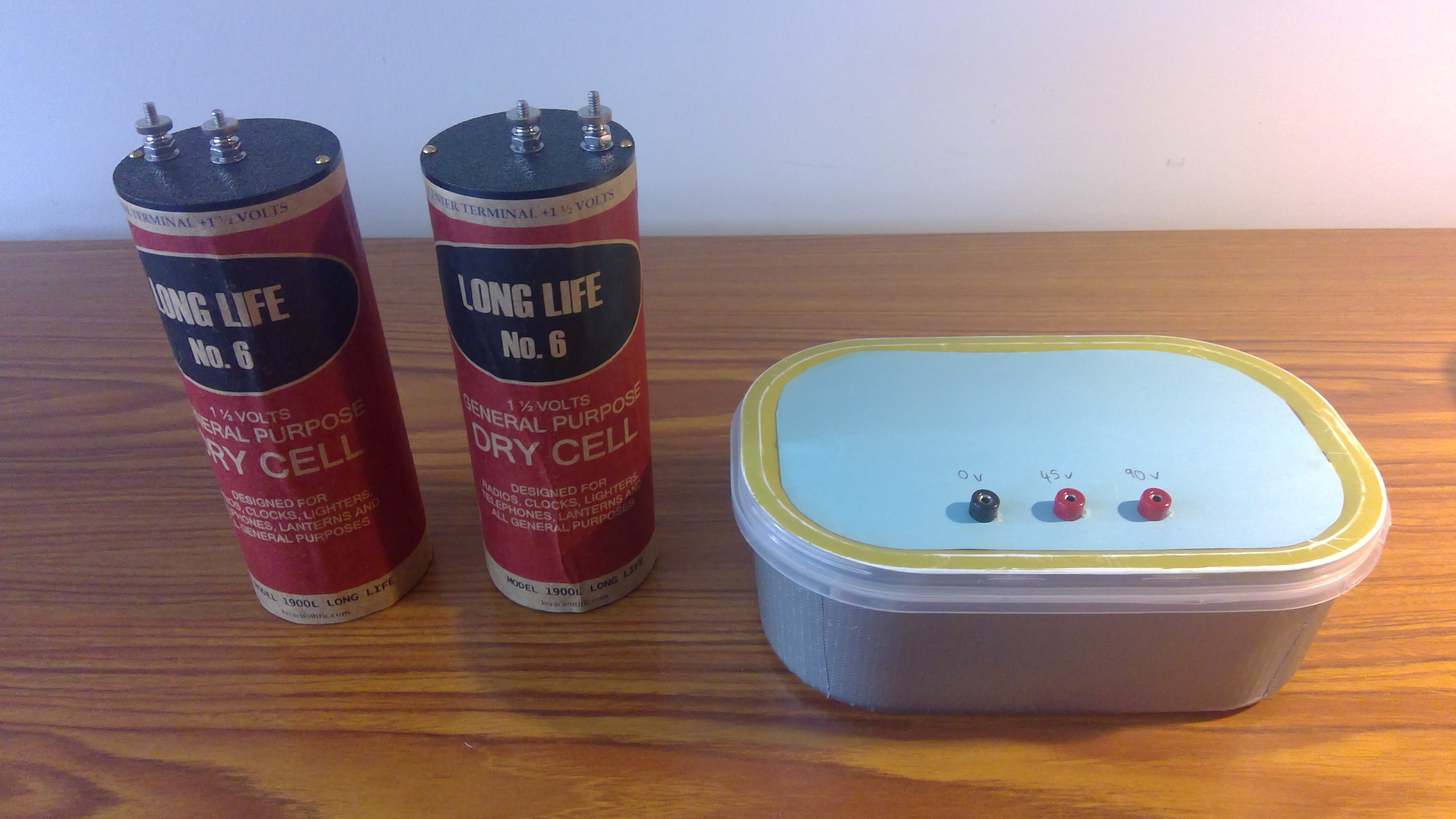
- To make this work, the radio will have a tuned circuit with a regenerative detector (triode or pentode), followed by an audio amplifier that drives headphones or a loudspeaker. Low voltage batteries are needed for the vacuum tube (valve) filaments, and higher voltages for the detector and the amplifier. The radio is built on a wooden "breadboard" to make construction easier and to avoid metalwork (although it may need a metal front panel). These techniques are known to experimenters from the 1920's.
- The design process will be iterative, this means I make it up as I go along . But there should eventually be a "useful working version" that can receive radio stations. Anyone following along should be able to reproduce it themselves, and will hopefully understand the design decisions that were made.
Background Information
- "RCA Receiving Tube Manual RC-19", (c) 1959 Radio Corporation of America. My copy is a reprint, but any original or reprint from about 1950 to 1970 should do. It provides the pinouts and details of the tubes / valves in use.
- "Secrets of Homebuilt Regenerative Receivers", C. F. Rockey, (c) Lindsay Publications Inc 1996. This has good information on construction techniques and some sample circuits from publications of the 1930s.
- Use https://tdsl.duncanamps.com/tubesearch.php to look up details of individual tubes / valves
Tools and Equipment
I'm new to hackaday and just spotted a "components" section which I will use. It's important to write up the other tools and equipment needed, so here we go:
- Basic wood working tools such as a handsaw, set square, ruler, and a sanding block and sandpaper. Use these to make a "breadboard" and wooden runners that go underneath.
- [Optional] Wood varnish and a paintbrush, to cover up scratches on the breadboard and to make it look nice. Use water soluble varnish, otherwise you will forever be throwing away gummed-up paint brushes.
- A hand drill and drill bits. Use these for "starter" holes for wood screws. Also if you have an aluminium front panel you need the drill to make the holes for the components on the panel.
- Soldering iron and solder.
- A multi-meter, any kind will do.


 Wasim Sahu
 Dimitar
Wow, that's a long trip back in electronics history. 👍 I wonder if you are in the running for the oldest components used in a HaD project.