Close
0%
0%

Accessibilità

Accessibilità aims to do what Arduino did for Microcontrollers for accessibility electronics and interfaces for Wheel chairs and similar

avrAVR
Similar projects worth following
Accessibilità is a family of open source hardware and software for wheel chairs! Starting with control interfaces first with the eventual goal of producing an entire open source electrical system someone can use to build a wheel chair or retrofit an existing one with a more modular, robust, and serviceable one.

Accessibilità

Accessibilità is a family of open source hardware and software for wheel chairs! Starting with control interfaces first with the eventual goal of producing an entire open source electrical system someone can use to build a wheel chair or retrofit an existing one with a more modular, robust, and serviceable one.

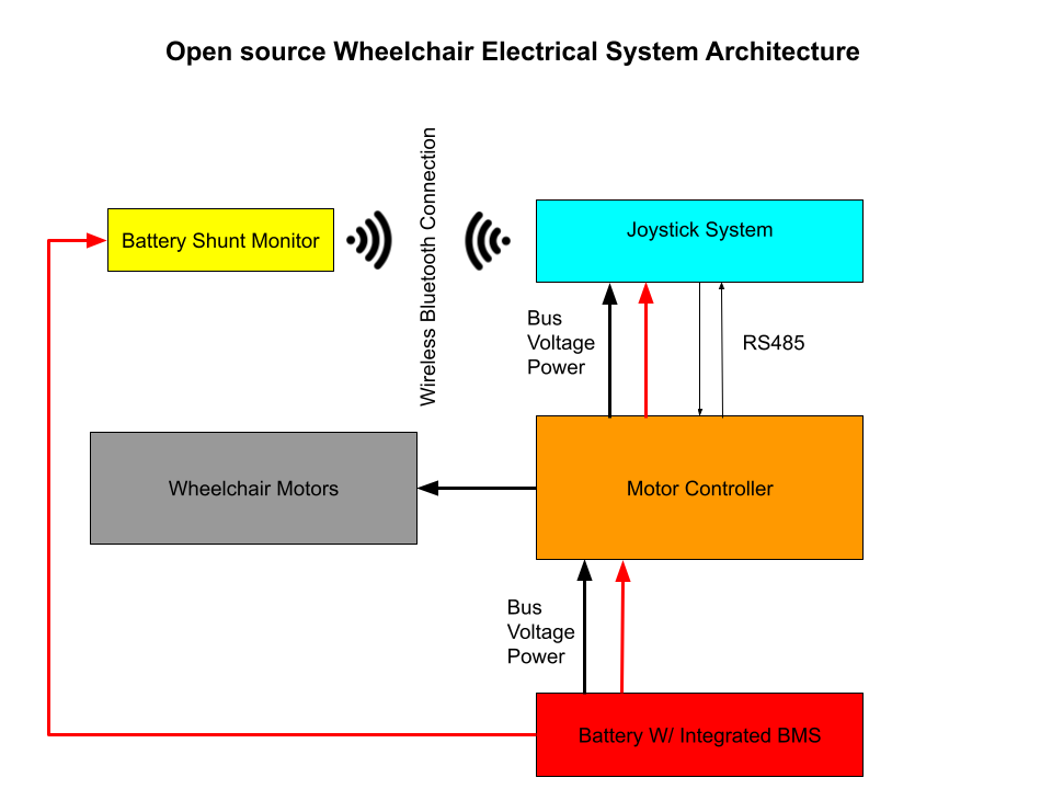
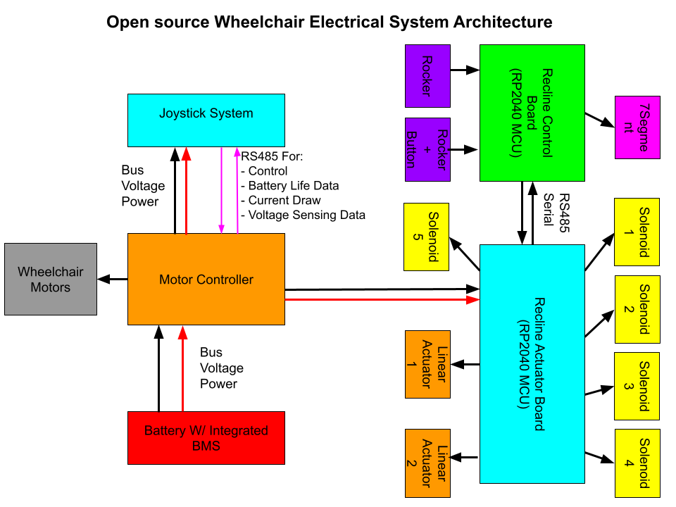
Overall System Architecture we aim to achieve as a retrofit system for the Omegatrax Wheel Chair :
Projects:

JoyStick-HID

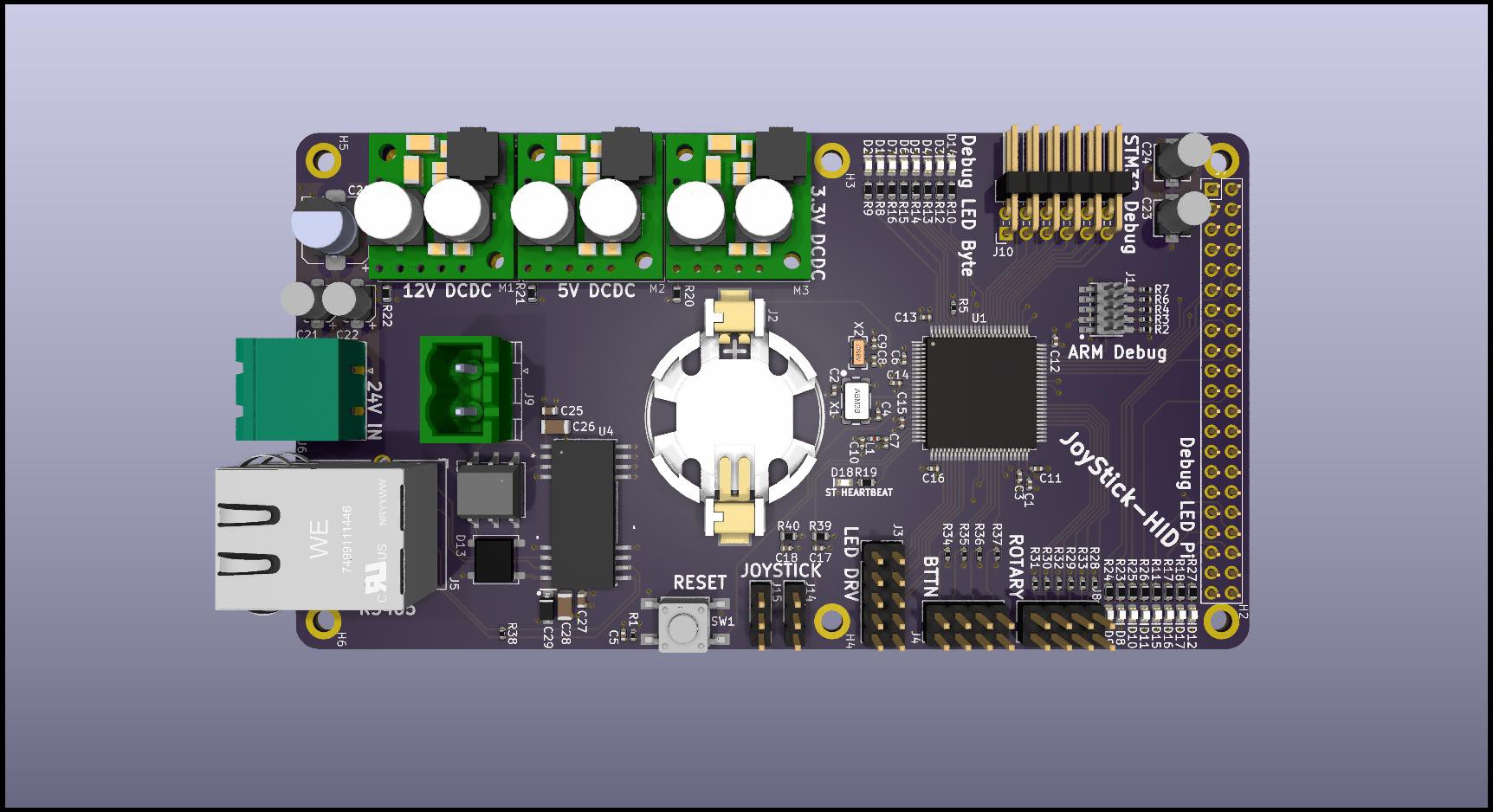
A custom open source PCB for controlling an open source wheel chair! This PCB contains all the necessary electronics for interfacing and powering all the components/peripherals that will be used to build a wheel chair human machine interface consisting of this PCB, analog JoyStick module, buttons, rotary switches, and 3D printed housing. JoyStick-HID is just one of the many PCBs being developed for our open source wheel chair electrical system we are developing with the Accessibilita project for the Mobility Independence Foundation (themif.org) !!

Quick Specs:

  • STM32F446RET6 100TQFP ARM Cortex M4 Microcontoller
  • ARM Cortex M Serial Debu Interface/connector for in system programming and development
  • MAX3535ECWI+T RS485 Transceiver for communicating with main motor controller
  • D24V22F5 2.5A 5VDC Voltage Regulator Module
  • D24V22F3 2.5A 3.3VDC Voltage Regulator Module
  • 24V Power Input with High Current Pheonix Contact Connector
  • 8 Debug LEDs for STM32F446RET6
  • Onboard Battery for STM32F446RET6 RealTime Clock
  • Interface for JoyStick, JH-D202X-R2/R4 Joystick 5K https://protosupplies.com/product/jh-d202x-r2-r4-joystick-5k/
  • Interface for two Rotary Switches
  • Interface for 8 Momentary swiches/buttons
  • Interface for LED driver board, this additional board drives LEDs in the arm wrest indicating battery level and current set speed
  • STM32 will run FreeRTOS w/ Custom Processes written for all functionality with priority scheduling for safety rated functions.

This board is intended as a developmental platform that can function in the field, it has all the features needed to control the wheel chair with additional feature that will make software development easier.
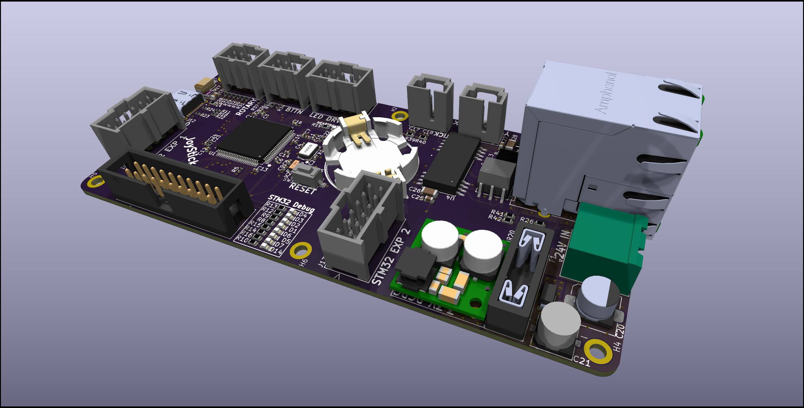
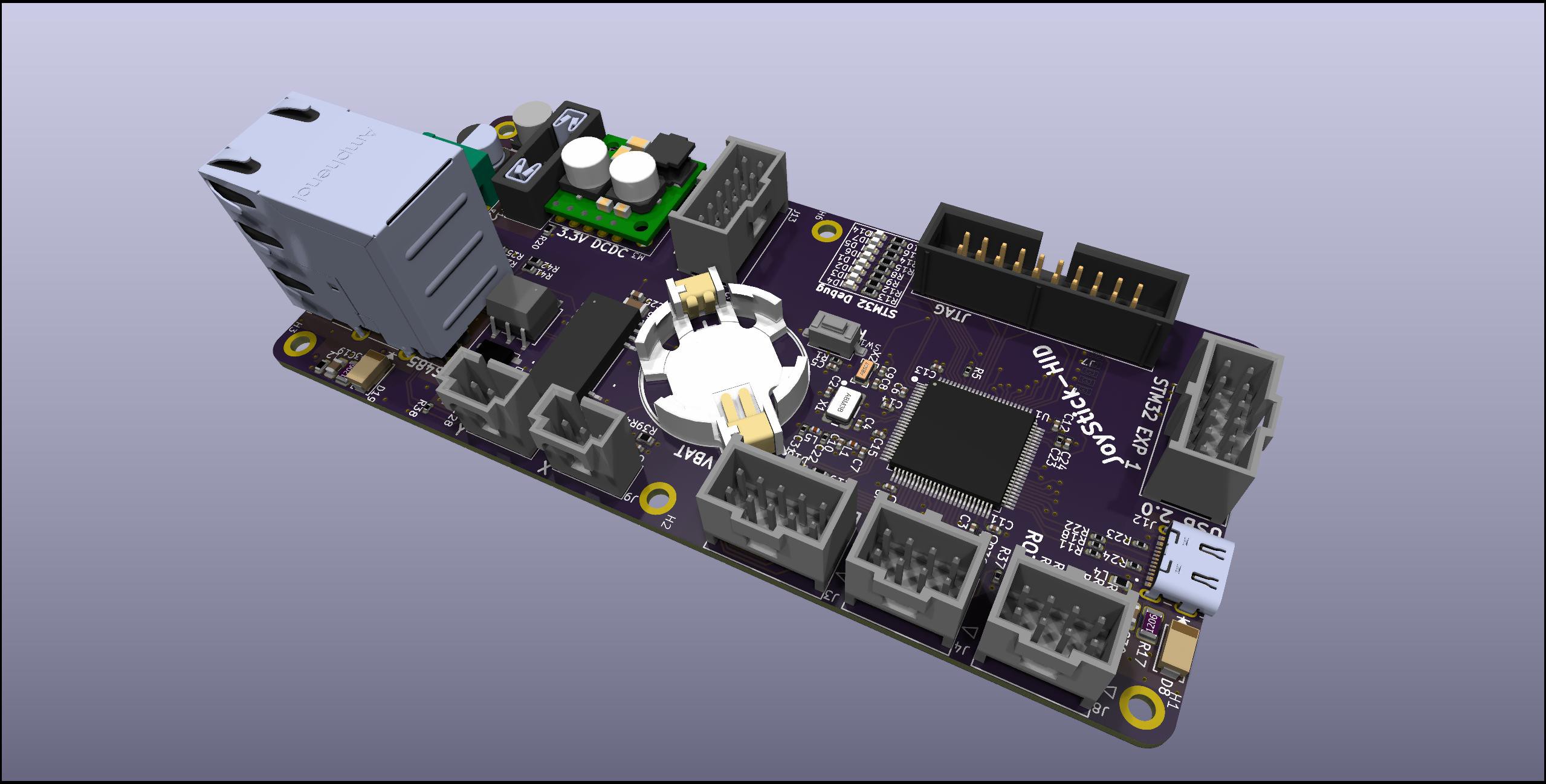
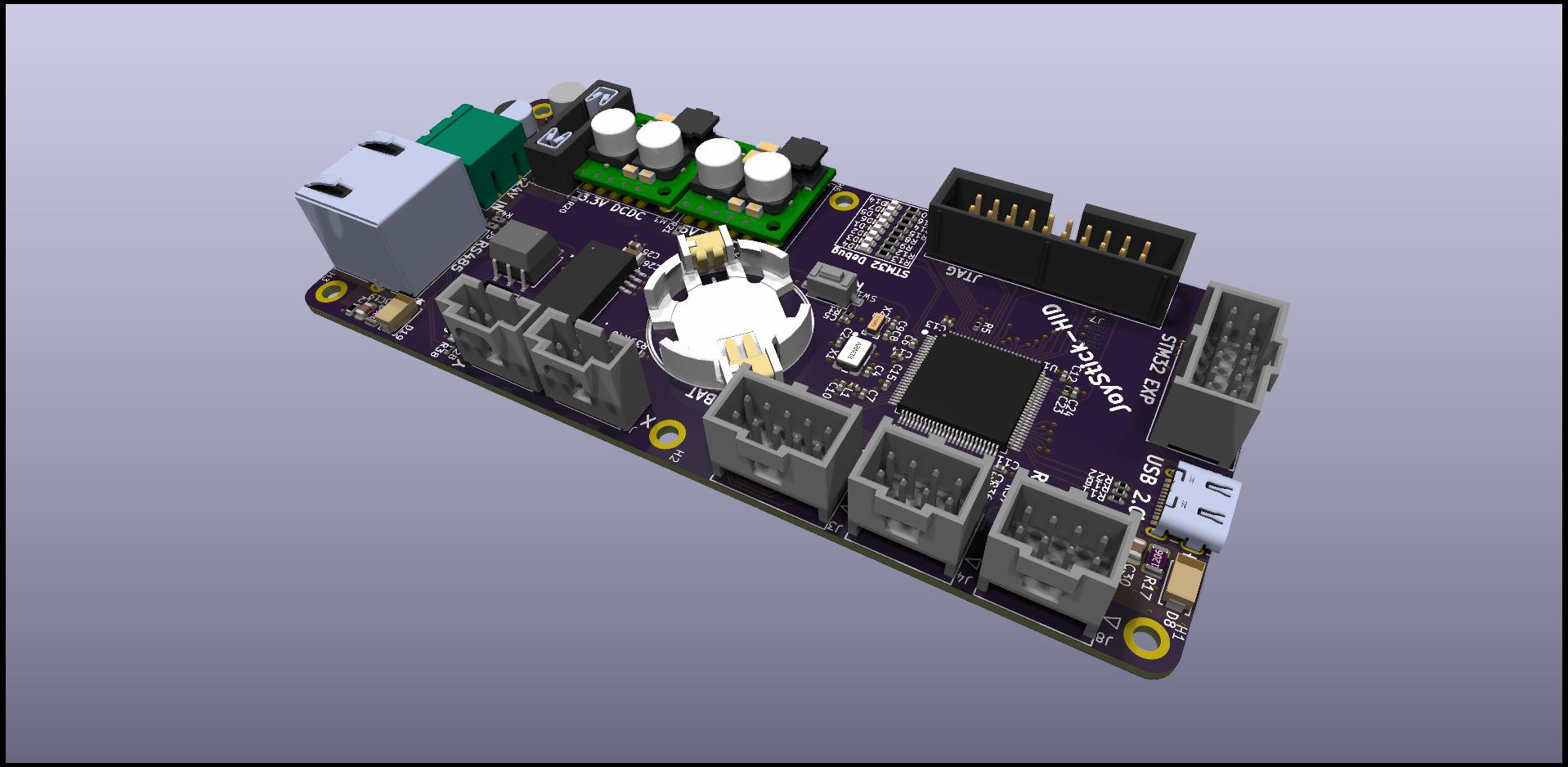
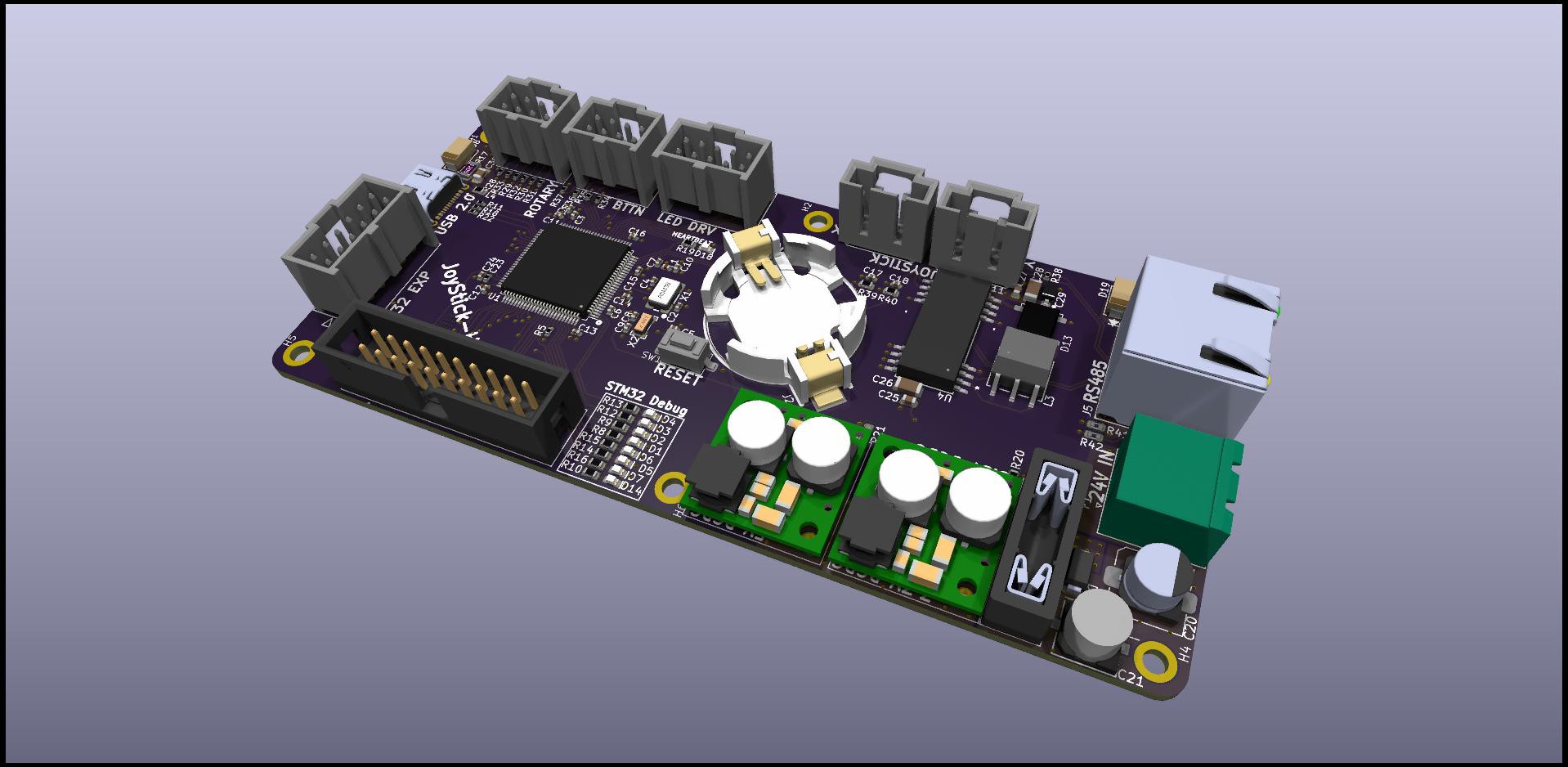
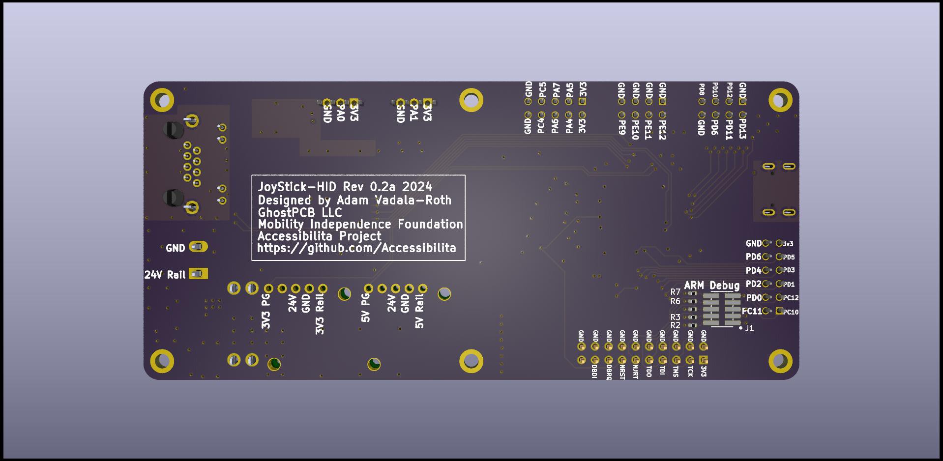
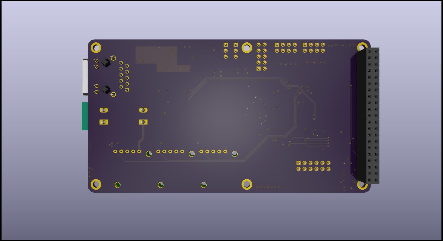
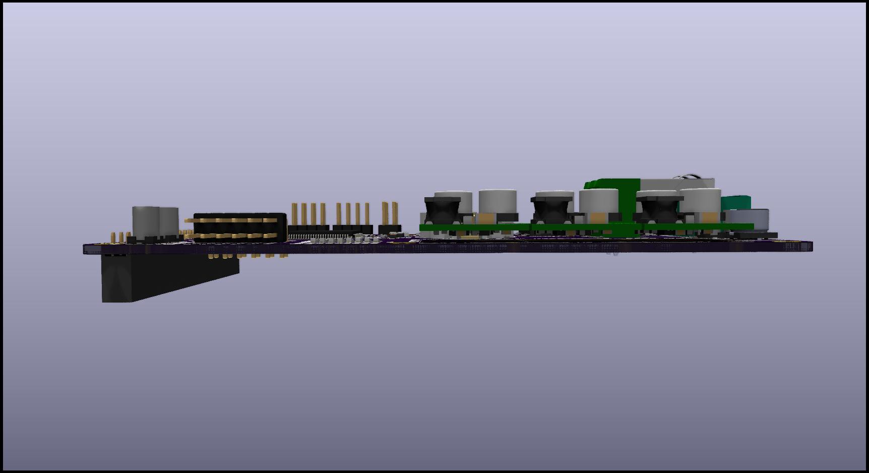
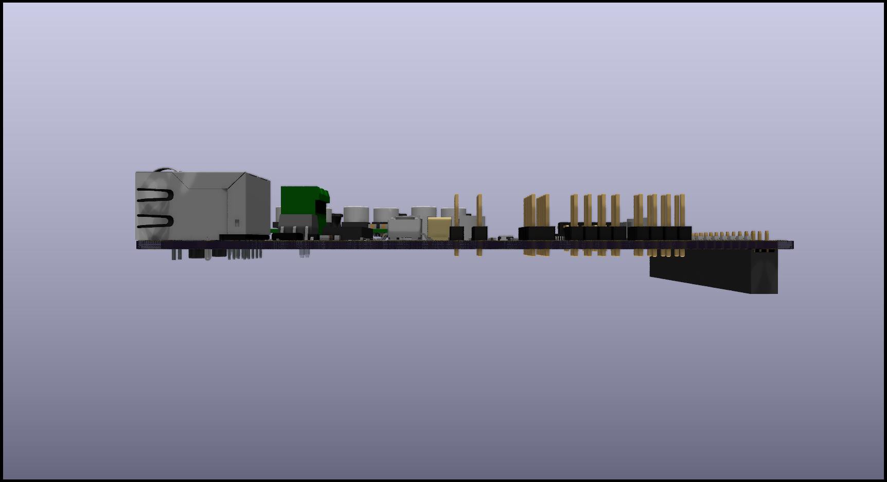
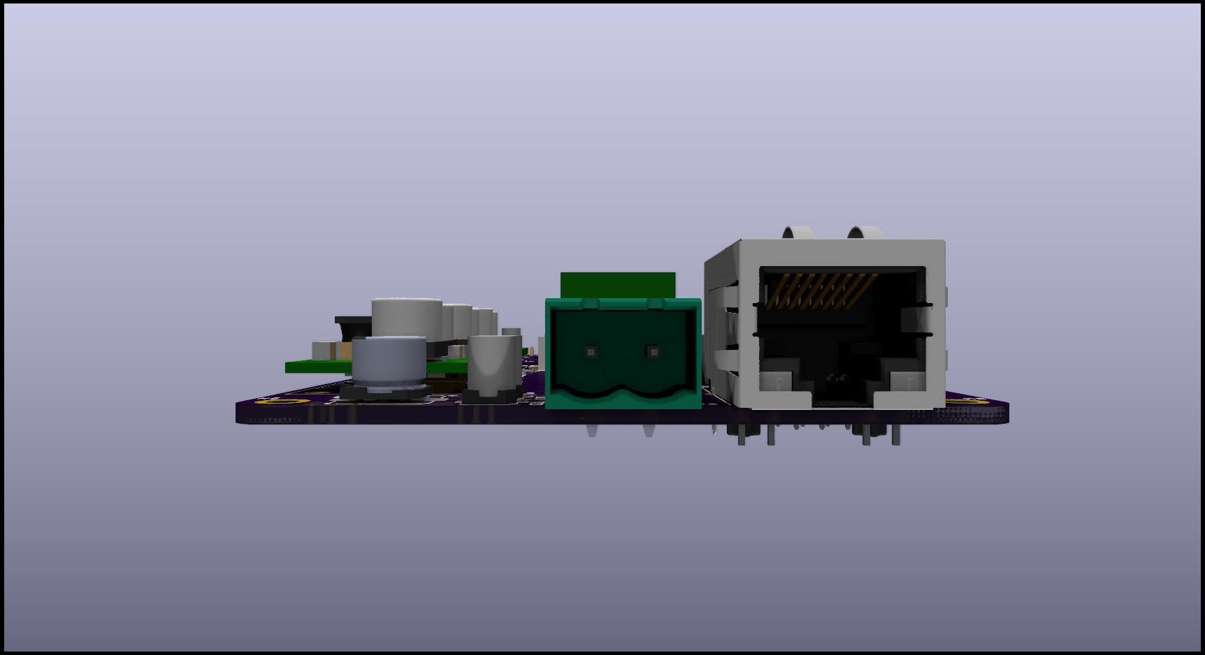
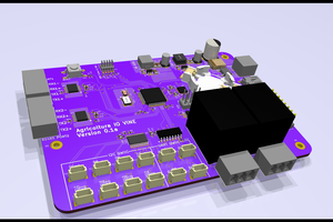
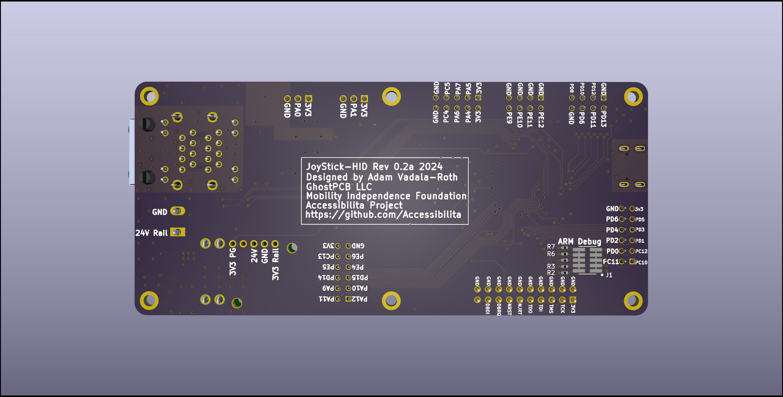
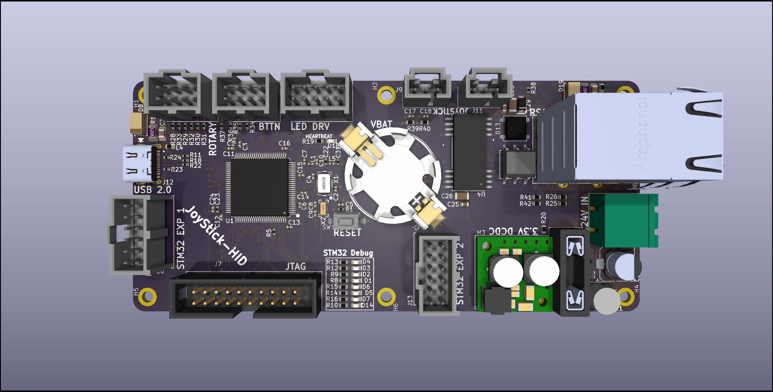
3D Renders of JoyStick-HID Hat in KiCAD 8.0 3D Viewer
Chair Recline System

The Recline control system allows the wheel chair user to adjust the recline position of their chair at their leisrure. Its a complete electrical controls system with with safety in mind. The system is split across two piece of electrical hardware design as two separated printed circuit boards. The First board functions as the controller and human machine interface, the second board functions as an intelligent controller for the actuators, solenoids, and air compressor related to controlling the chair recline postion and the chair's pneumatic suspension.The human machine interface board is called the Reline Control board, and the actuator controller is called the Recline Actuator Control board.

The system is split across two printed circuit boards for a couple of reasons, the signals from the switches and buttons are low voltage signals, running those signals through long wires would cause problems witha accurately reading the position of the rocker switches and buttons due to voltage drop, the LEDs in the 7 segment display have a low forward voltage and need to be close to the driving source for them to work, if the wire is too long voltage drop would prevent the LEDs from turning on, the other reason is the actuators and solenoids are high voltage signals and need to be mounted close to the control board. The Recline Control Board will be mounted on the arm rest of the users's dominant hand, it runs off 24V power and sends commands to the Recline Actuator control board via RS485 serial communication. The Recline Actuator Control board will be mounted in a secure location most likely at the botton of the chair between the chair and it the rolling chassis, it will be fed 24V power and connect to the Recline Control Baord via RS485.

Block Diagram:...

Read more »

JoyStick-Hat_BOM.ods

0.1a version Bill of Materials for Digikey

spreadsheet - 29.85 kB - 11/02/2024 at 23:52

Download

  • Hello After a Long Time !!

    AVR11/03/2024 at 00:35 0 comments

    Hey folks got a lot to update everyone on this project since I last posted about it ! So even though I haven't updated this page in a while I have been working on the project in some way shape or form! Over the summer I was able to devote a lot more time to the project and make considerable progress. In the spring we aquired all the components on the BOM for the JoyStick-HID part of the project. Around July tweaks were made to the PCB the boards were ordered and a few additional BOM items were procured !!
    Anyways talk is cheap here's the pix:

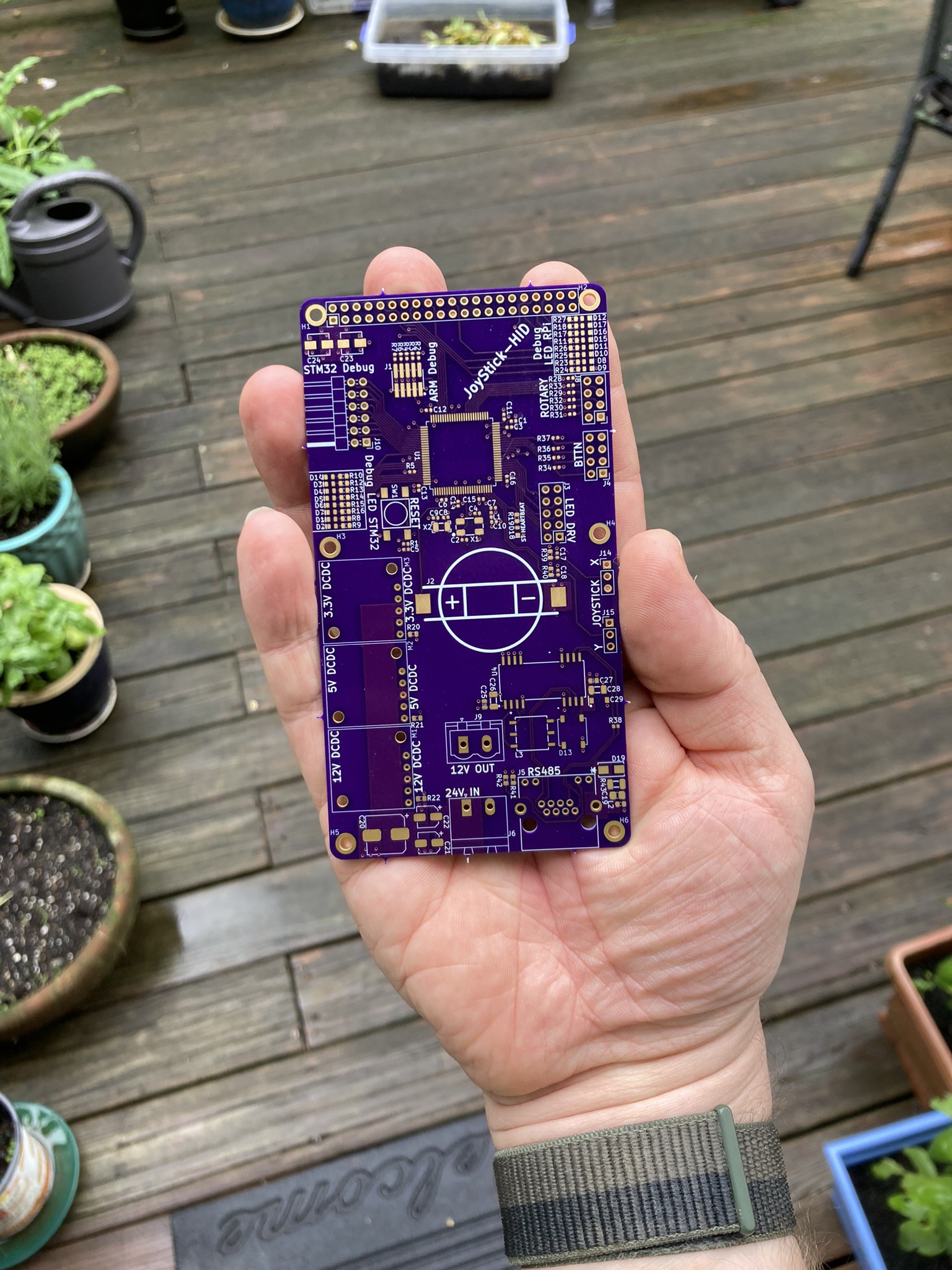
    Raw PCB from OSHPark.com go check them out for your PCB needs !


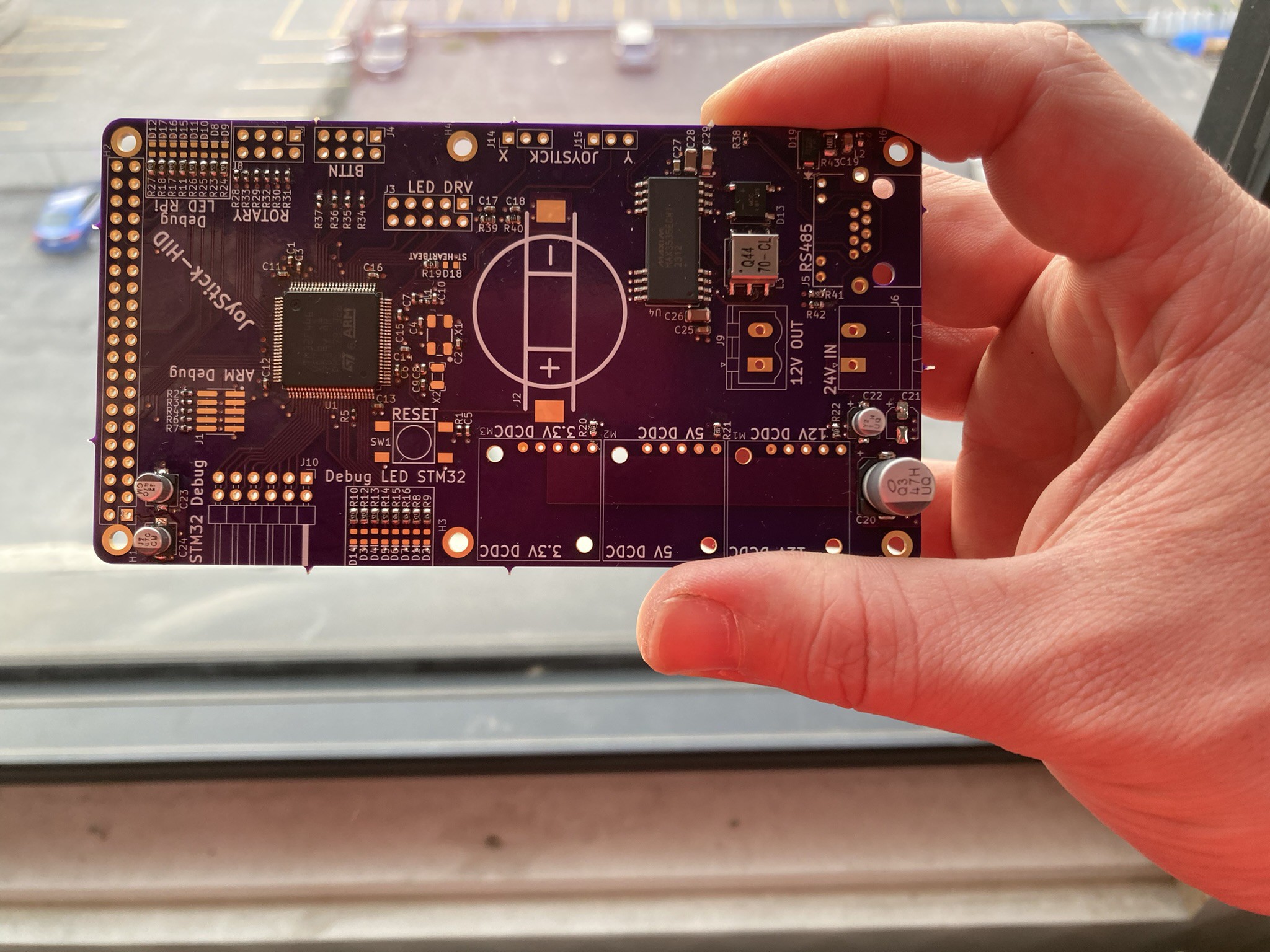
    Partially assembled during sunset !


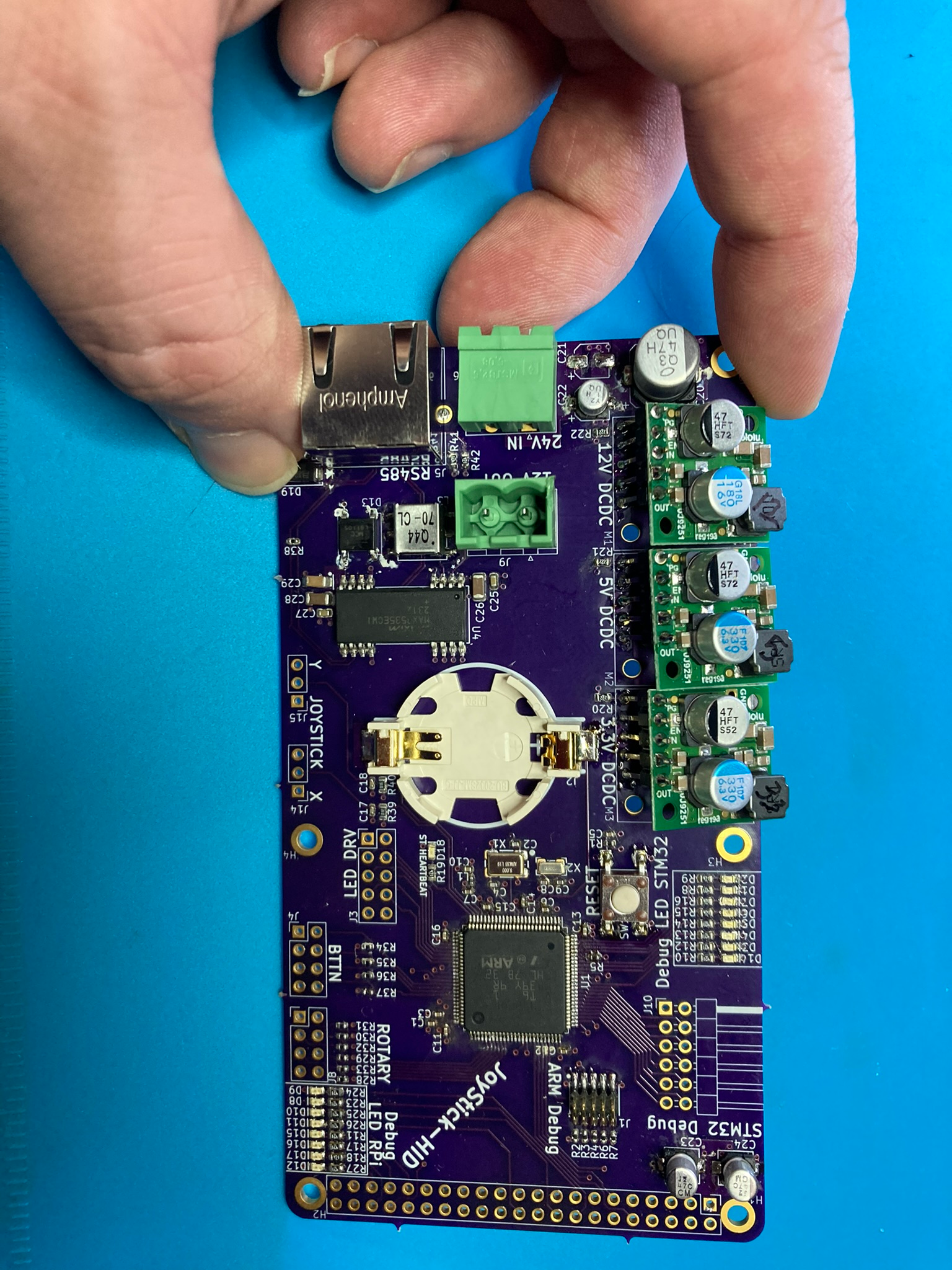
    Fully Assembled (as much as it could be fully assembled)

    Assembly
    The assembly of the JoyStick-HID PCB went fairly smoothly. A few errors were disovered along the way. The holes for the pin headers for the DCDC regulator modules were too small, they had to be carefully grafted onto the PCB with solder. This happens with PCB design you're bound to make silly mistakes like this.

    Assembly issues totaled out:

    • Footprint for Raspberry Pi Header connector is wrong, its 42 pins should be 40
    • 10uF caps on input = footprint too small!
    • C19 footprint too big
    • Max chip Pin 1 legend too hard to see
    • RS485 diode orientation legend not on PCB
    • STM32 Pin 1 legend not there
    • Header holes for DCDC regulator modules too small had to hack them on there.
    • ARM Cortex M Debug Connector issues, signals are flipped around, the footprint numbering doesn't correspond to the symbol numbering.
    • All DCDC Regulators Work and produce correct voltage
    • Debug LEDs Work
    • GPIO and ADC Interfaces Work

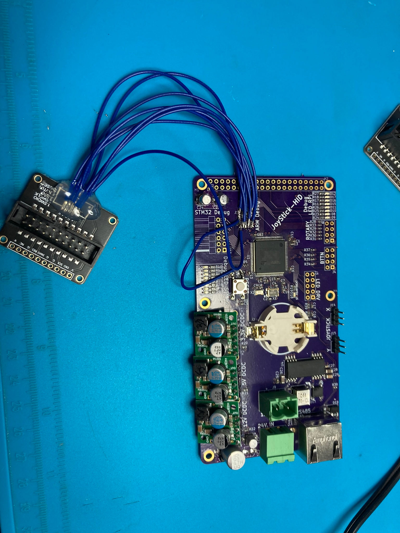
    The biggest issue with assembly and testing was the programming interface pins were flipped. This too a lot of debugging and testing different things to figure out why the chip was not connecting to the programmer. I've designed around this MCU many times over the years but I noticed that the connector used for the cortex M Debug interface wasn't always the same and I made new footprints for new components added to my library. These days a lot of the premade parts are fairly accurate I usually download them and manually check them and make some adjustments. What I did notice on this connector was the pin numbering was flipped on the footprint vs he symbol flipping the connector signal layout. 

    The way round this was to solder in the programmer:

    Hooked up to Programmer (ST-Link V2)

    Up And Running:

    Firmware for testing was written in C using STM32CUBEIDE and STM32CUBEMX for port mapping and initialization code generation. Demo code can be found here: https://github.com/Accessibilita/JoyStick-hat-firmware
    Demo of code running:

    During the assembly of the JoyStick-HID a separate analysis of the RPi 5 was carried out, since the plan was to have the JoyStick-HID be a RPi hat and have the RPi 5 do advanced functions like interface with USB HID devices as alternative control input or interface with battery's that use bluetooth for information reporting. The RPi5 was deemed too hot for a sealed enclosure. The JoyStick-HID when enclosed has to be effectively water proof we are shooting for IP67/IP68. While I assembled the first JoyStick-HID I started redesigning the new version. I eliminated the RPi5 early on in the redesign after discussing with the rest of the team. Instead we are going to design a separate module that contains an RPi5 a hat with dual RS485 interfaces all housed in an enclosure with a passive heatsink sealed, but that's for another project log.

    Anyways version 0.2a of the JoyStick-HID is based entirely around the STM32F44VET6 MCU the formfactor of the PCB is still RPi inspired in terms of shape and hole spacing, board is still 4 layers. Notable changes other than RPi are removal of 12V regulator as we don't need it, addition of 20 pin ARM JTAG, fuse and crobar circuit,  and all connectors swapped over to locking clipped versions. 

    Enjoy the renders:

    That's it for the JoyStick-HID ! We are...

    Read more »

  • Major Update: JoyStick-HID Hat Design Completed !!

    AVR03/12/2024 at 20:00 0 comments

    Hey folks !! this project page hasn't been updated in a while but the project has been worked on continuously over the past 7 months or so, just nothing very notable to update on since the last update. The biggest news is the PCB design for the JoyStick-HID Hat is finished, well at least the rev 1 version of the design is done. We have done an internal design review with our engineering team and made a few tweaks and we will be fabricating prototypes very soon. Somethings have changed with the design but everything is mostly the same!

    The RPi will be a version 5 instead of a 3/4 as originally planned. Instead of running a custom application on the RPi we will be using ROS2 with a few custom ROS packages running on the RPi to achieve what we wanted it to do. ROS Package for interfacing with the bluetooth battery management system built into the LiFEPoE battery and sending LED information to the JoyStick-HID hat for display to the user. A ROS package for interfacing with USB HID devices and translating the data out of them into JoyStick XY parameters and other datatypes so that users can use HID devices like keyboards/mic/Xbox controllers to control their chair or have someone else control their chair. There will be more ROS packages but we are still in the early stages of software design.

    Anyways here the hardware !! Some quick specs to get things started:

    - STM32F446RET6 100TQFP ARM Cortex M4 Microcontoller
    - ARM Cortex M Serial Debu Interface/connector for in system programming and development - MAX3535ECWI+T RS485 Transceiver for communicating with main motor controller
    - D24V22F5 2.5A 5VDC Voltage Regulator Module
    - D24V22F3 2.5A 3.3VDC Voltage Regulator Module
    - D24V22F12 2.5A 12VDC Voltage Regulator Module
    - 24V Power Input with High Current Pheonix Contact Connector
    - 12V Power output with High current Phoenix Contact Connector
    - Rapsberry Pi 5 Running ROS2, directly power via header from 5VDC rail
    - 8 Debug LEDs for STM32F446RET6
    - 8 Debug LEDs for RPi 5
    - Onboard Battery for STM32F446RET6 RealTime Clock
    - Interface for JoyStick, JH-D202X-R2/R4 Joystick 5K https://protosupplies.com/product/jh-d202x-r2-r4-joystick-5k/
    - Interface for two Rotary Switches
    - Interface for 8 Momentary swiches/buttons
    - Interface for LED driver board, this additional board drives LEDs in the arm wrest indicating battery level and current set speed
    - STM32 will run custom FreeRTOS or ROS-Micro more to follow

    This hat is intended as a developmental platform that can function in the field, it has all the features needed to control the wheel chair with additional feature that will make software development easier. The final version will be much simpler and low cost, this is only the beginning.


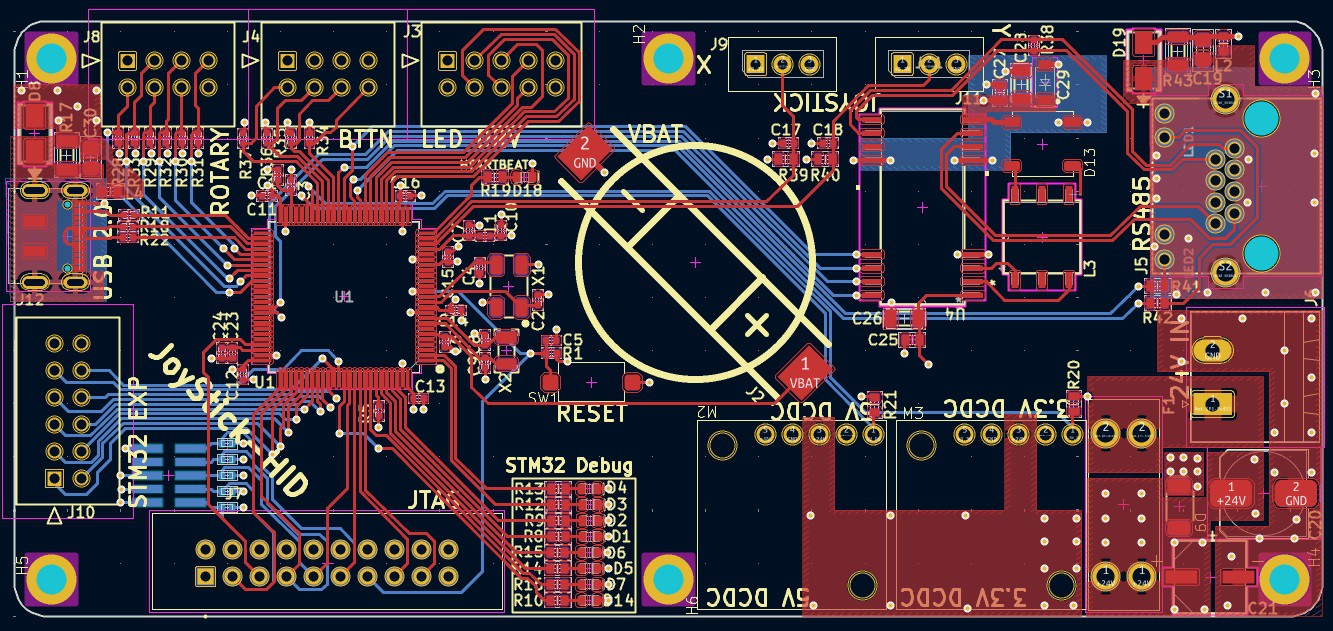
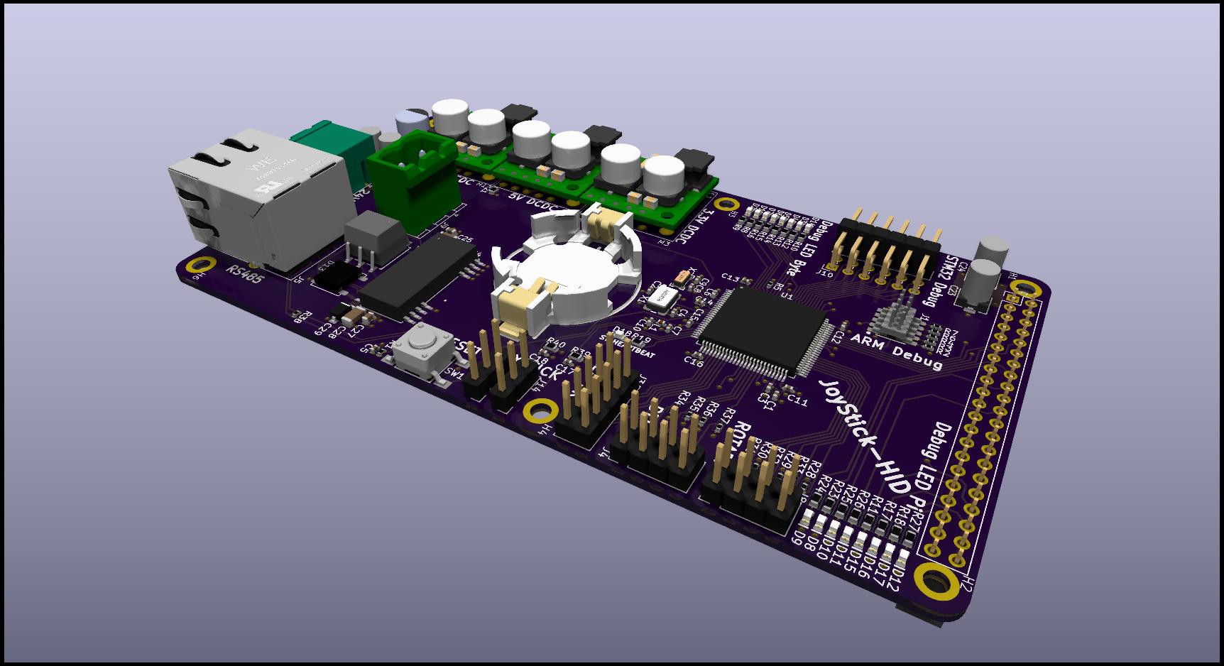
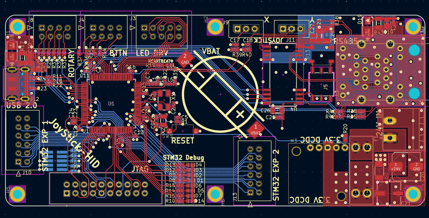
    And of course the moment you've been waiting for ! Renders of the PCB !!

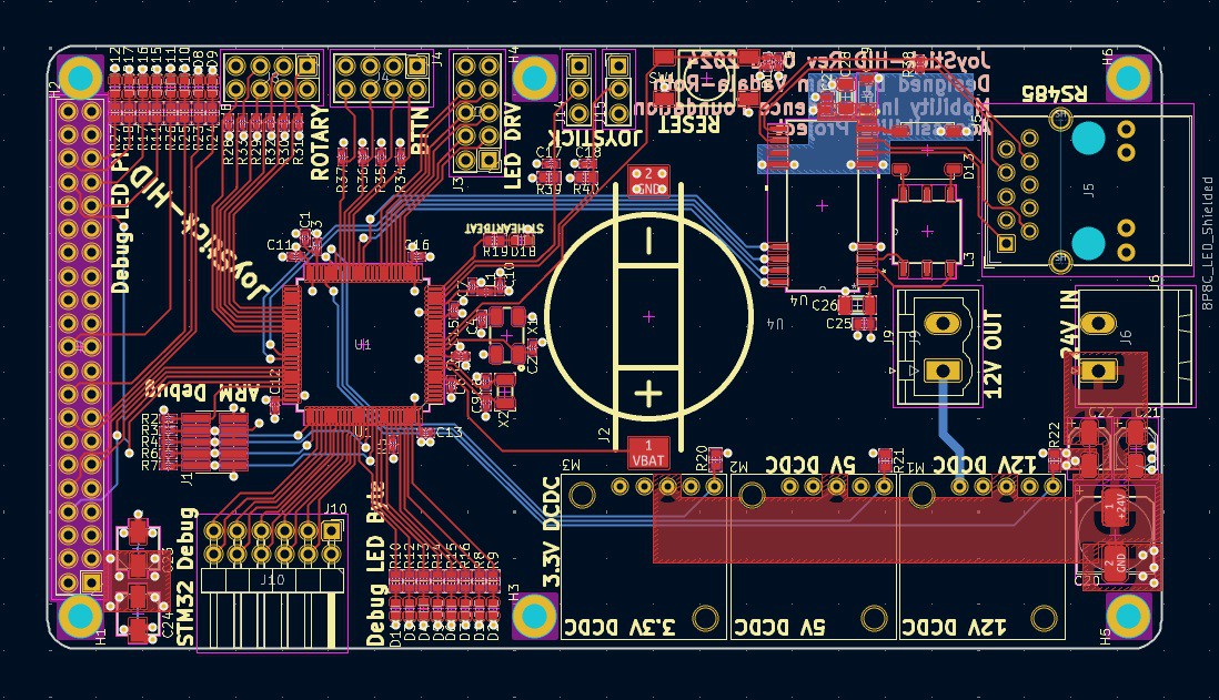
    2D Render:

    3D Renders:

    That's all for now! More to follow! Thanks for your continued support of my open source projects !


  • WHAT IS UP HACKADAY !? ITS BEEN A WHILE LETS UPDATE

    AVR08/02/2023 at 18:13 0 comments

    This project has sat on the backburner for quite sometime but I have been thinking about it alot over the last few months and in the last couple of days I have completely overhauled my approach and developed a complete electrical system architecture for an open source wheel chair. We are going to prototype this system and graft it to an existing wheelchair owned and operated by our fearless leader Tom !

    A Block Diagram says a thousand words as I've always said, so here we go !! Here is the overall architecture of the system !!

    To begin with an electric wheelchair electrical system isn't super complicated to begin with in terms of the physical hardware (custom safety rated firmware for all the embedded devices in the system is the biggest challenge), I distilled down the group discussions we have been having amongst our team and boiled it down to the architecture in the diagram.
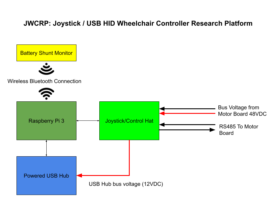
    You will notice that the biggest change there is no mention of the USB HID Black box device I was originally going to develop, I decided that I still want to do that, but I would rather make a custom Joystick shield for the Raspberry Pi that has the Joystick module and all the other controls/indicators the wheelchair user will need to operate their chair but also have the ability to interface with any USB HID device at the same time. This will allow use to build a traditional electric wheel chair control interface, but also allow us to audition and test many other off the shelf devices and explore what we can do with them for potential users. This is effectively going to be a complicated research platform in its first iteration and as we go I hope to develop it down into a completely integrated, robust, fully embedded RTOS based system with no Linux SoC require.

    The overall architecture hinges on two pieces of custom hardware, and the rest are off the shelf components. A cool guy named James is designing a custom motor controller that will be able to driver all the different motors in the chair from a single PCB. The other piece of custom hardware is the Joystick/USB HID Wheelchair controller research platform, an RPi Hat that contains all the standard wheelchair controls, with the RPi being used for USB interfacing and Bluetooth interfacing.  The Joystick Hat will communicate with the Motor controller via RS485, the motor controller will also function as the power distribution board and send the bus voltage to the Joystick, the Hat board will have an integrated PSU to step down the bus voltage for all onboard devices.  The two off the shelf devices are the massive LifePoE battery with built in BMS, and the Bluetooth shunt used for monitoring and tracking the battery performance since it doesn't have any way for the BMS to report data to us.

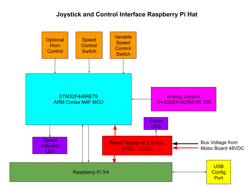
    Moving on to the main attraction !! I am designing the Joystick /USB HID hat! Like I said before and I will say it again, block diagram is worth 1000 words:

    Basic Feature set:

    - Classic Wheel Chair Joystick

    - Dual Speed switch

    - Variable speed switch (for fine tuning of speed)
    - LED indicator for power/power level
    - LED Indicator for Set speed
    - USB configuration port, so the user can adjust all the operational parameters to their unique preferences/needs
    - Optional Horn control

    To make all this work I am designing a custom Hat PCB for the RPi, here is the block diagram and tech specs so far:


    Tech Specs:
    - RPi 3
    - STM32F446RET6 ARM Cortex M4F MCU

    JH-D202X-R2/R4 5K 10K Joystick module

    - Ti DCDC Converters
    - Switchcraft Mechanical Switches

    That's all for now !

  • Colloborator: The Mobility Independence Foundation

    AVR05/20/2023 at 22:45 0 comments

    The Mobility Independence Foundation (MIF) is a non-profit organization dedicated to promoting and supporting mobility independence for individuals with disabilities. The foundation aims to enhance the quality of life and opportunities for people with disabilities by providing them with access to adaptive vehicles and mobility equipment. By doing so, MIF seeks to empower individuals to lead independent and fulfilling lives.

    https://themif.org/

    The MIF was founded by my friend Thomas Quiter and I was brought on to bring my robotics and hacking experience to their organization.  Please visit their website and learn about their organization, we will be doing amazing things together !!

  • RPi and Python Lets Go

    AVR05/20/2023 at 22:38 1 comment

    To make things quick and dirty easy I am developing the blackbox around the RPI Zero Wireless !! The program will be in Python, it should be sufficiently fast for this application and it will be easy to interface with lots of USB and Bluetooth devices via open source libraries very easily !! I whipped up a python script super fast to start the concept on.

    Hardware:
    - RPi Zero Wireless

    - PSU

    - USB HMI Mouse

    - Header for RPi GPIO Pins

    Software:

    - https://github.com/adamjvr/py-rpi-hmi-pwm

    I need to dig through my piles of stuff to find where my RPi zeros are but I got a few to dedicate to this project !! Take a look at the code and give me your feedback, I've never written python before but I've programmed in other languages before.

  • Individuals That Use Wheel Chairs We Need Your Thoughts and Opinions !

    AVR05/16/2023 at 15:33 2 comments

    Title says it all !! I myself am an able bodied person so I don't have the personal experience of living with a wheel chair or relying on accessibility technology. Which is why I want to hear from those who do and what they have to say, this project is open source and its meant to help as many people as possible so its important to get their voices heard and ideas integrated into the designs.

View all 6 project logs

Enjoy this project?

Share

Discussions

Gary wrote 11/27/2023 at 02:31 point

I'm disabled and almost at the point where I can't walk anymore and this is really something that will be beneficial for many people. I'm really looking forward to any updates and I really appreciate the work going in this. I have a lot of the components used so far, so I'm going to try and get one going as well. Good luck with everything! 

  Are you sure? yes | no

AVR wrote 03/12/2024 at 17:42 point

Hey Gary feel free to message me anytime, we would love to have your input and thoughts on the project, we have several disabled people working with us on the project and we would love more opinions/thoughts/ideas from those who will benefit from our technology !! I am posting a big update in regards to this project today !

  Are you sure? yes | no

Similar Projects

Does this project spark your interest?

Become a member to follow this project and never miss any updates