-
1Coil Winding Setup
Step 1 :
Lock one end of the 50um wire into the groove of the chuck and loosely tighten the chuck tightening screw
![]()
Step 2 :
Place about 1-2mm of the Ferrite core into the chuck, then with the spacer jig, push the ferrite core in at the exact distance into the chuck using the tailstock.
![]()
Step 3:
Tighten the chuck to clamp down on the ferrite core, and then remove the spacer and the tailstock
![]()
Step 4:
Place the 1mm spacer on the other end of the Ferrite core, and gently flush the tailstock to the spacer. Tension the copper wire through the wire guide.
![]()
-
2Winding the Coil
Step 1:
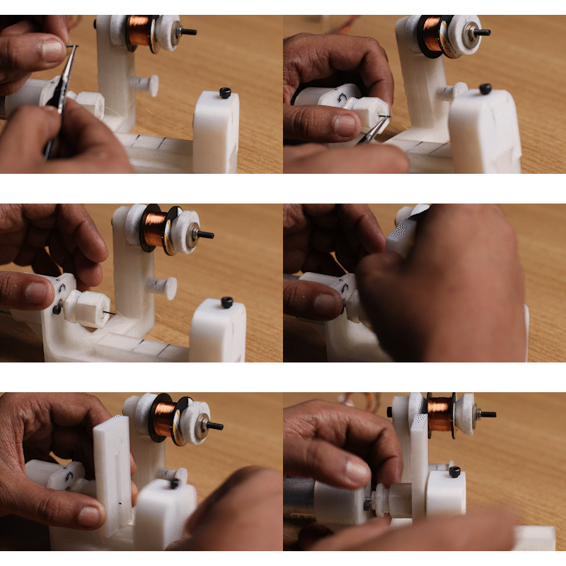
Manually wind the first few turns neatly and make sure there is adequate tension in the copper wire
![]()
Step 2:
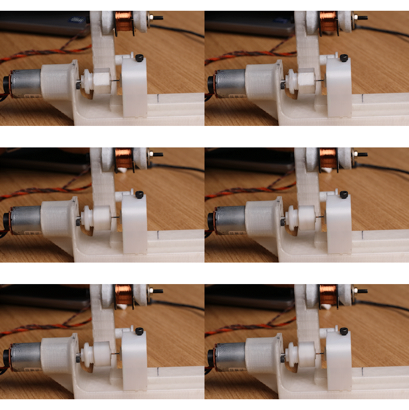
Turn on the motor, monitor the coil winding, and guide the coil if required to evenly spread the diameter of the winding.
![]()
Step 3:
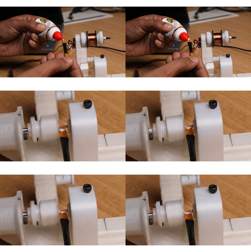
At the end of the winding, using a paintbrush, apply some PVA-based glue to the coil
![]()
Step 4:
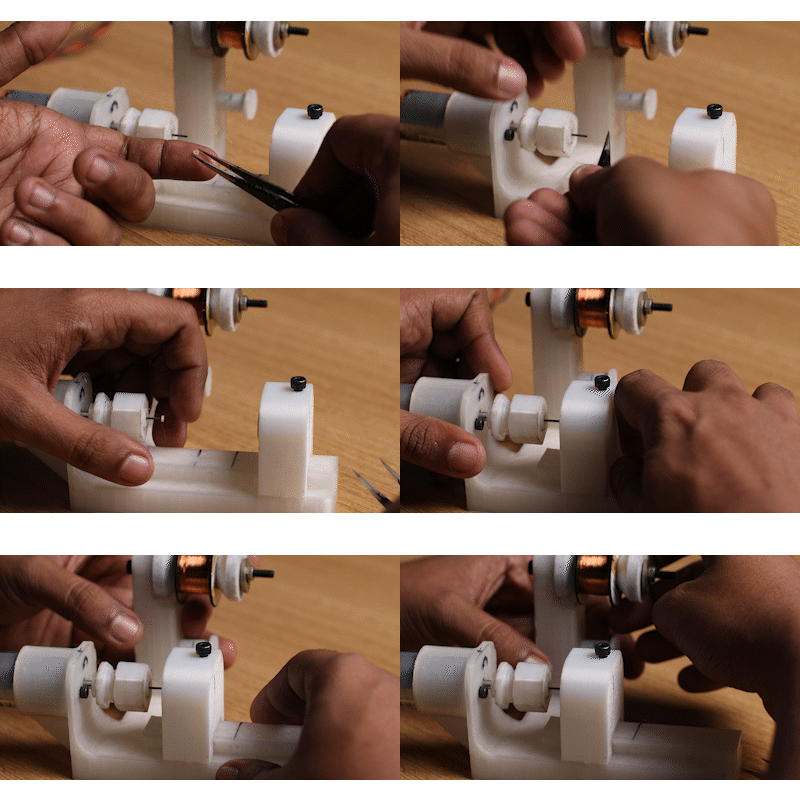
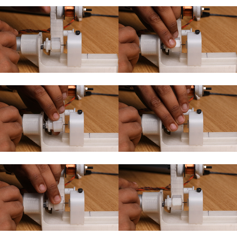
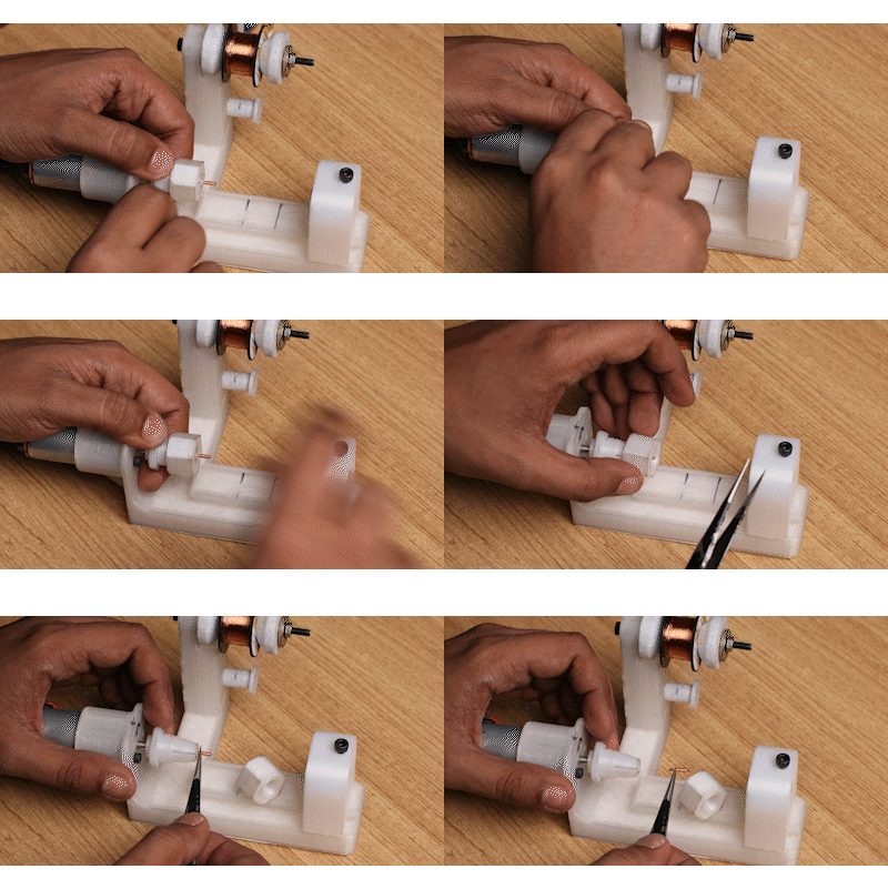
Carefully remove the tailstock, and the spacer. Then loosen the chuck and remove the finished coil. Allow for glue to dry
![]()
Step 4:
Marvel at the fruits of your labor
![]()
-
3Cam Assembly
Step 1 :
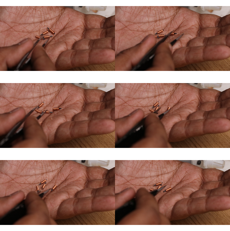
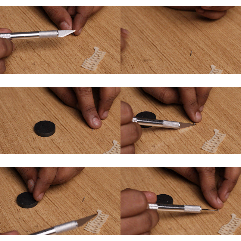
Using a Xactro knife, remove individual 1mm magnets from its stack, and place them on a magnet. Mark a side of the magnet with an identifier, so you can make out the polarity, and hence know the polarity of all the micromagnets. you just need to make sure all are polarised in the same direction.
![]()
Step 2:
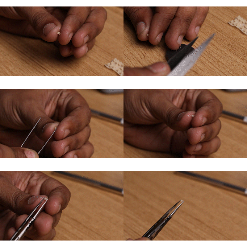
Remove a cam from the 3D printed support tree, and clean the area where the support was stuck.
![]()
Step 3:
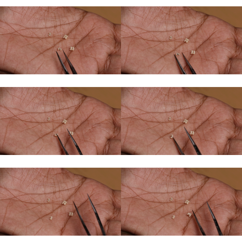
Using a tweezer pick up a coil, keep track of the magnetic orientation, and press-fit it into the 3D Printed Cam
![]()
Step 4:
Marvel at the fruits of your labor
![]()
-
4Braille PCB Pre-Assembly
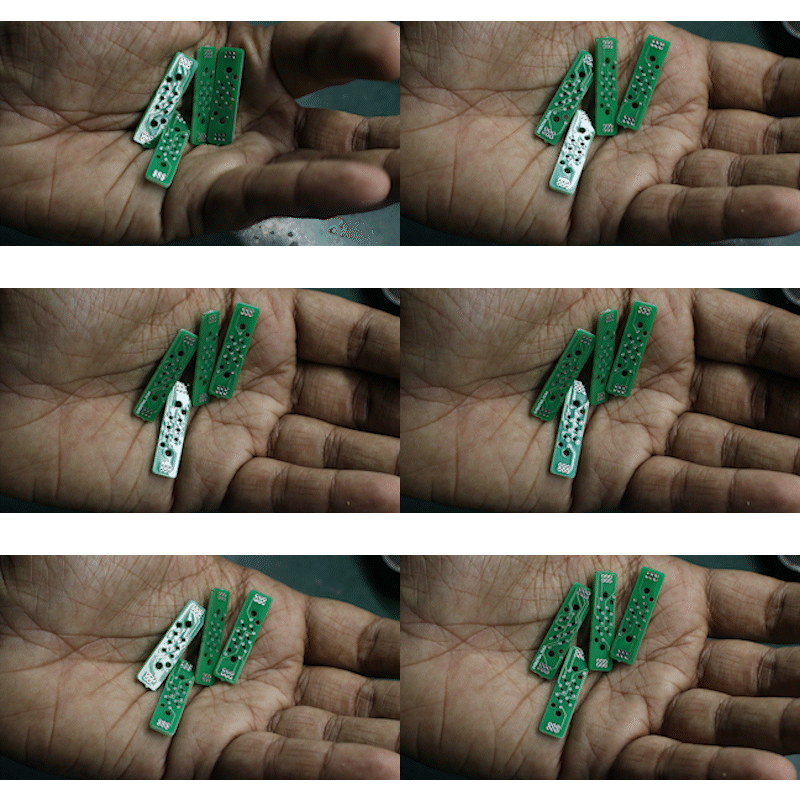
Step 1:
Take the base PCB's
![]()
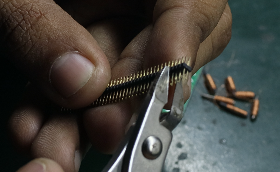
Step 2:
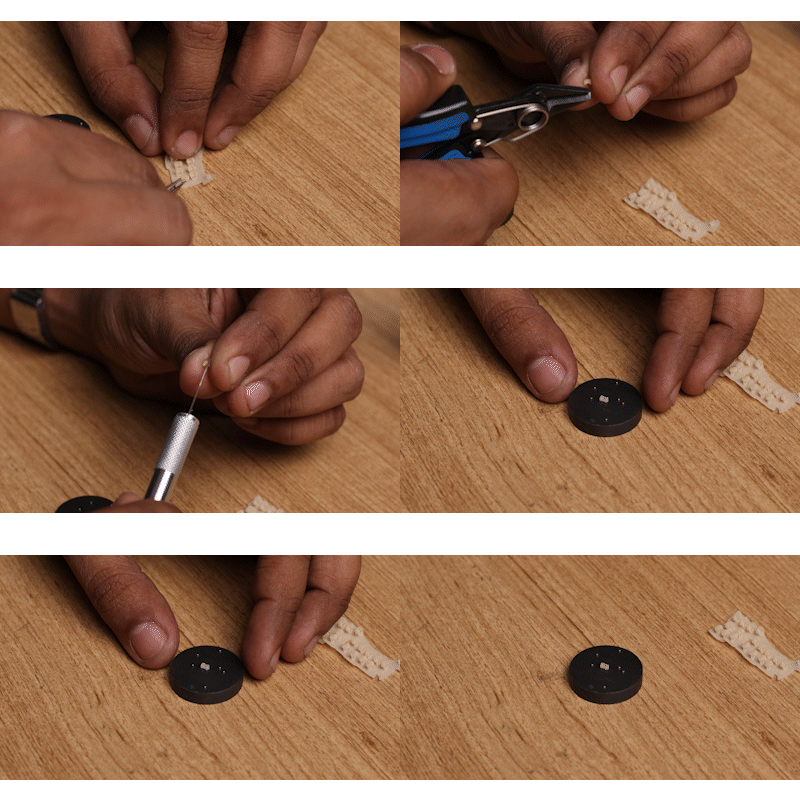
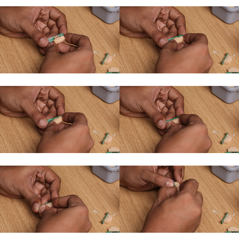
Cut 2x3 1.27mm headers from their strip
![]()
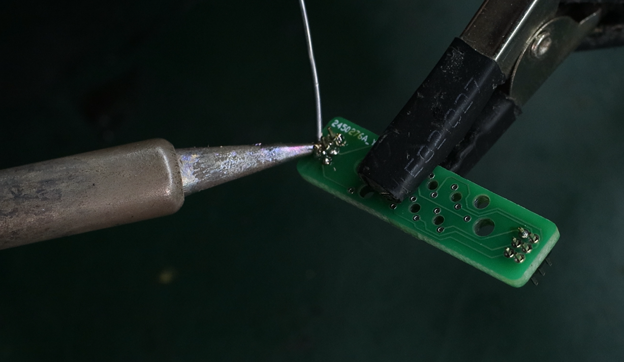
Step 2:
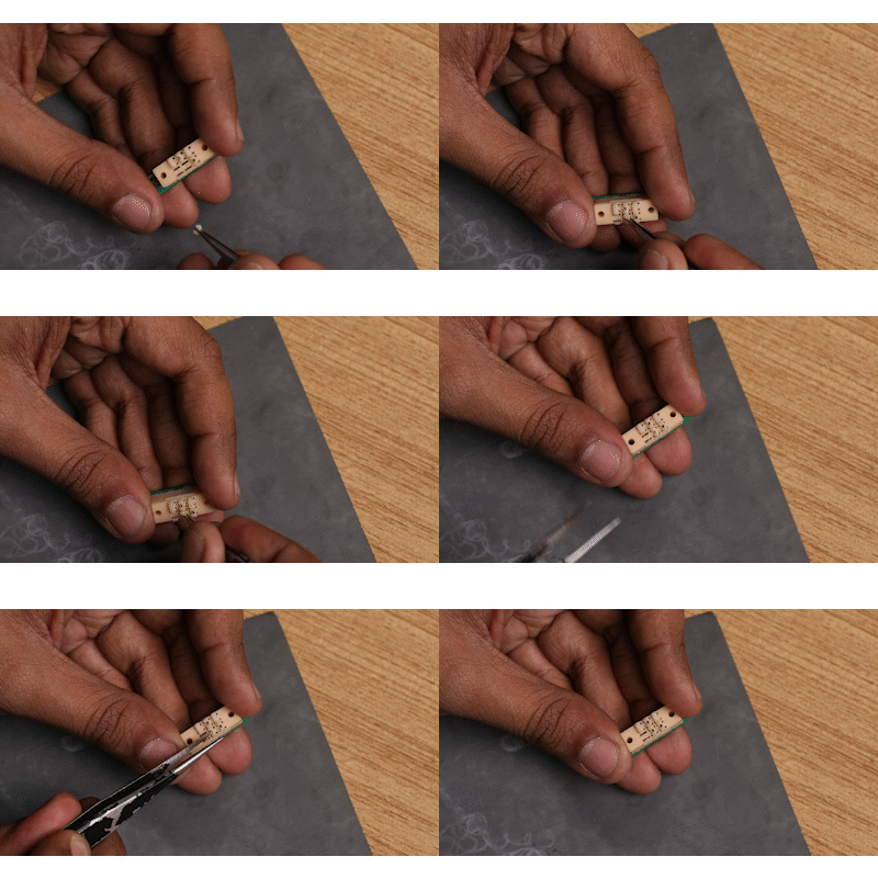
Solder them onto the Braille PCB, Silk side up
![]()
Step 3:
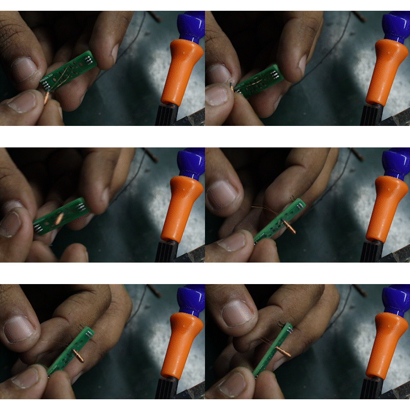
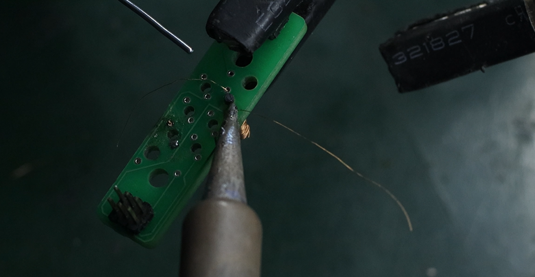
Thread the two ends of the wire through the small pads on the Braille PCB. The large hole in the center of the PCB is for the ferrite core, and there is a terminal pad for the copper to the top right and bottom left of each large hole.
On each coil, one wire will originate from the core, and one from its outer diameter. Just follow the same soldering convention while doing all your coils and thread the wires through the terminals.![]()
Step 3:
Solder
![]()
Step 4:
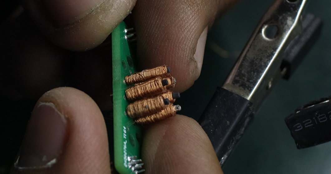
Repeat for all other coils
![]()
-
5Braille Dot & Braille Upper Assembly
Step 1:
Cut out the Braille dots and Braille Upper from the support tree, and clean up the support
![]()
Step 2:
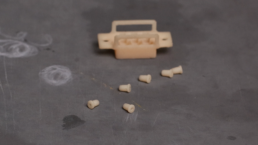
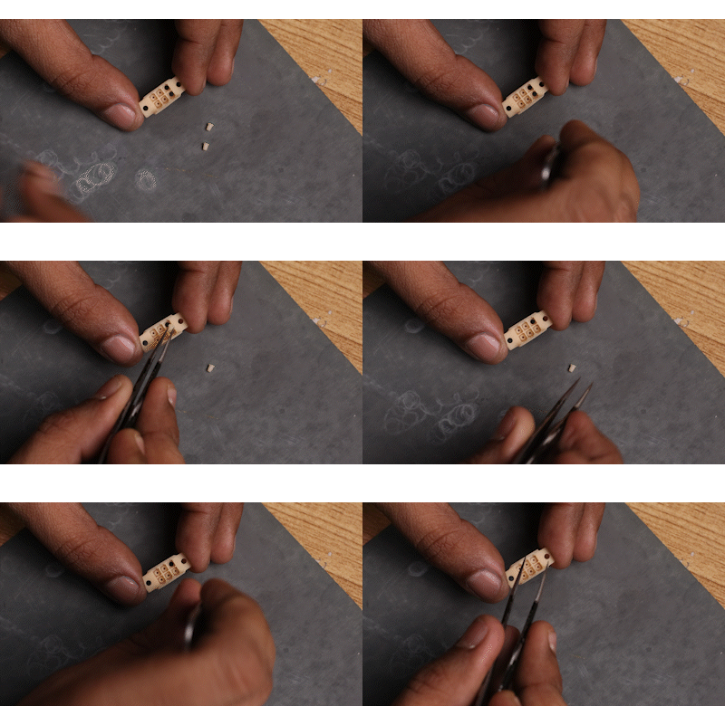
Place the dots into the braille upper.
![]()
-
6Braille Lower and Solenoid Assembly
Step 1:
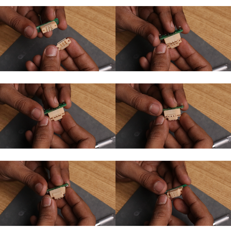
Bring the Braille Lower and the Coils together, Be careful in this step as to not break any of the coils. The notch of the braille lower should be facing away from the silk of the PCB
![]()
-
7Cam and Braille Lower Assembly
Step 1:
Pres fit the cams into the shaft holders of the Braille Lower part. Refer to the CAD design in this step, and orient the cams with respect to the notch of the Braille Lower part as per the design.
![]()
After placing it into the holes for the shaft, move the cam around and free up its movement
-
8Final Assembly
Step 1:
With the braille upper facing down so the braille dots don't fall out, push the braille upper assembly into it, until the snap-fit part snaps into place.
![]()
And you are done making one braille celll!
Repeat steps 1 through 8 to make more cells.
Electromechanical Refreshable Braille Module
Lowering the cost of Refreshable Braille Cells by using Electromagnetic Cam Actuators & 3D Printing
 Vijay
Vijay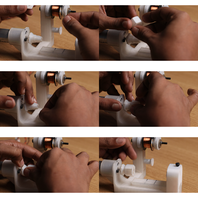

Discussions
Become a Hackaday.io Member
Create an account to leave a comment. Already have an account? Log In.
awesome job sir this is something I have been experimenting with for a while but ended going more mechanical, this works way better.
Are you sure? yes | no