Close
0%
0%

Electromechanical Refreshable Braille Module

Lowering the cost of Refreshable Braille Cells by using Electromagnetic Cam Actuators & 3D Printing

Public Chat
Similar projects worth following
The big drawback to refreshable braille devices has always been their cost. The loose rule of estimation applied to these products has translated into something like $100 to $150 per braille cell. A 40-cell display, in other words, may cost $4,000 to $6,000, while an 80-cell model will cost $8,000 to $12,000. And so it has been that, while desirable, braille computer access has been out of reach for many users of assistive technology.

It is thus of great value to lower the cost of individual braille cells in order to manufacture Refreshable Braille Devices at a price that is affordable to the Visually Impared community.

While commercially available braille displays use expensive piezo-electric actuated pins. This project employs an electromechanical system with off-the-shelf and easily manufacturable components, leveraging the accessibility of high-quality 3D Printers and micro-magnets to keep the cost low without compromising functionality.

HackadayPrize Video:


Table of Contents:

SubsystemLinks to Log/Document
Mechanical Development & Testing1st 3D Printed Prototypes
• 3D Printing: The Devil is in the Details
• Assembly and Single dot test
Two dot test
• Single Dot Test on PCB
• 12th time is the charm
Electronics/Firmware Development & Testing• Braille Cell Array Drive Circuit
Updated Drive Electronics
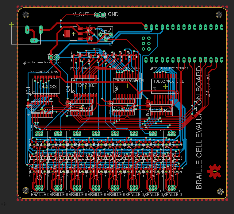
PCB Design of Braille Cell Evaluation Board
• Braille-Module & Driver PCB's
• Testing Electronics
• Single Dot Test on PCB
Solenoid-Coil Winding ToolCoil Winding Tool for Micro-Electromagnets
• Updated Winding Jig for Ferrite Cores vs Steel Cores
Technical DocumentsReferences & Previous Work
• BOM & Cost
CAD Design
PCB Source Files


Working Principle: 

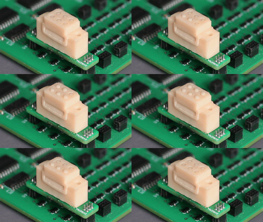
                       Fig. 1 Braille Cell Actuation Test

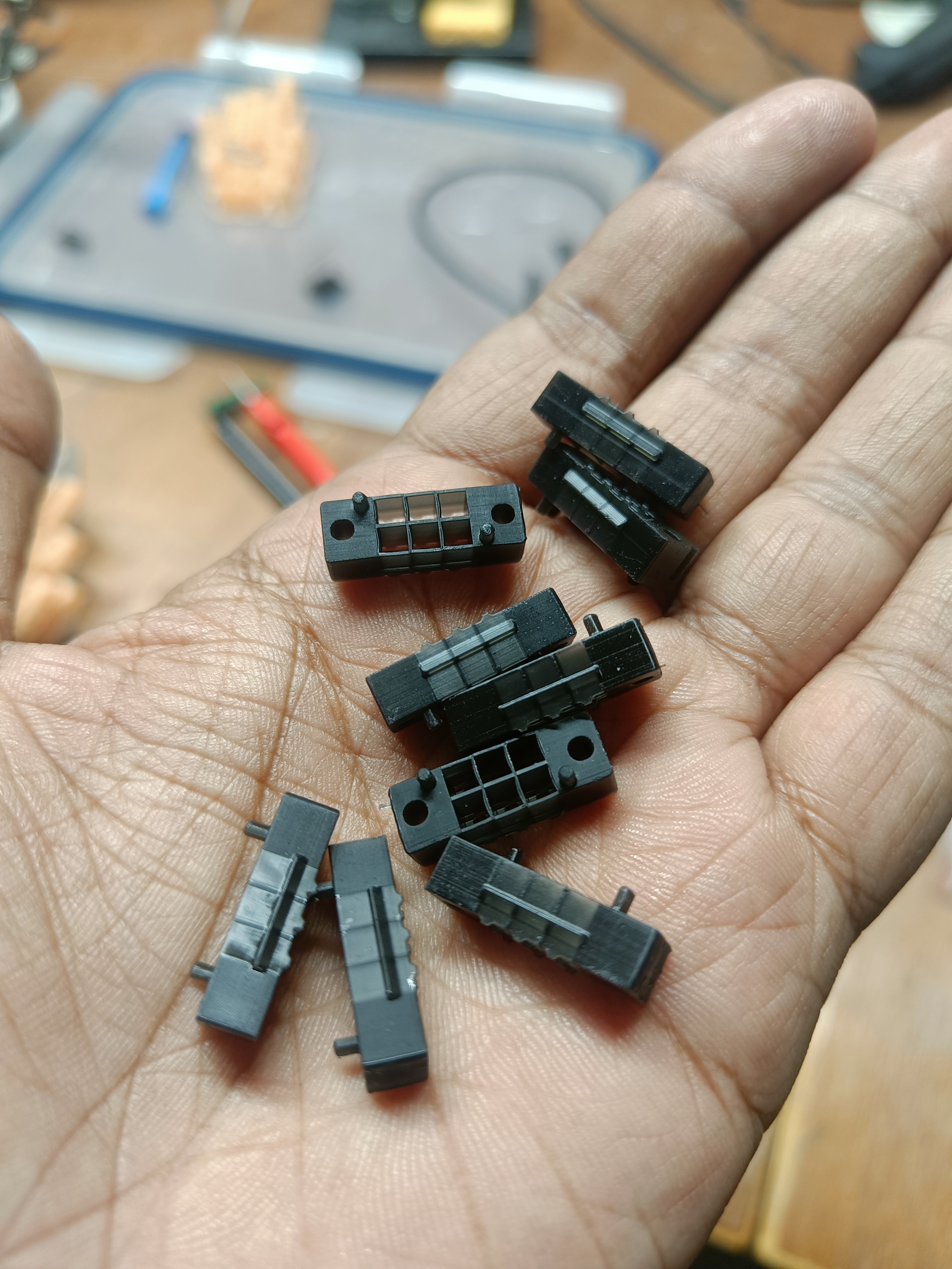
This is a 3D Printed, electromagnet-based braille display module that can represent braille characters. 

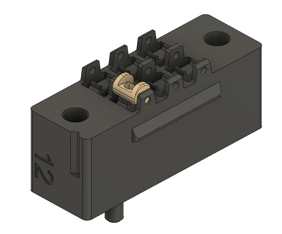
The key working principle is a cam actuator, consisting of an eccentric cam that has a rare-earth magnet embedded into it which is rotated to two stable positions by the action of an electromagnetic that changes its polarity. The rotation of the eccentric cam causes a braille dot to be lifted up or taken down.
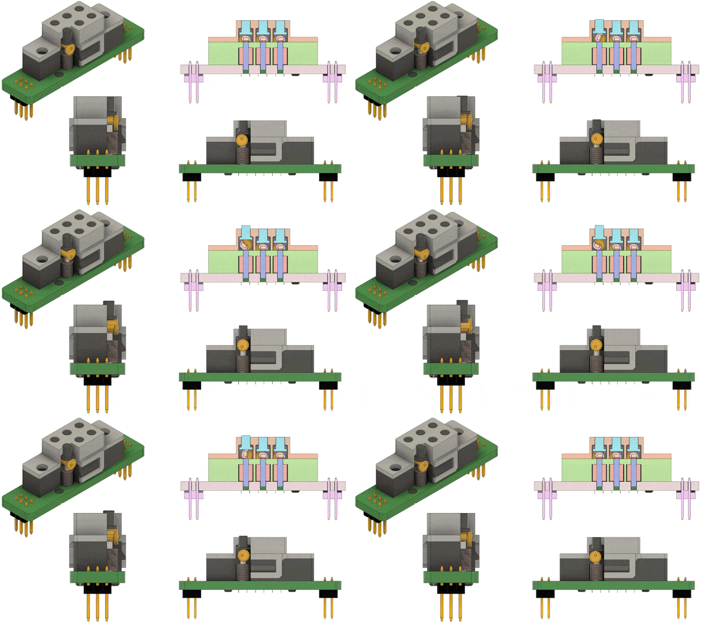
                Fig. 2 Braille Cell Working Principle

Once the Braille pin is lifted, and the cam rotates to its stable position, the weight of a finger on the pin (while reading braille) cannot back drive the cam. This not only satisfies the need for protrusion force of the braille pin but also that the electromagnet need not be powered once the pin has been lifted resulting in lower power consumption.
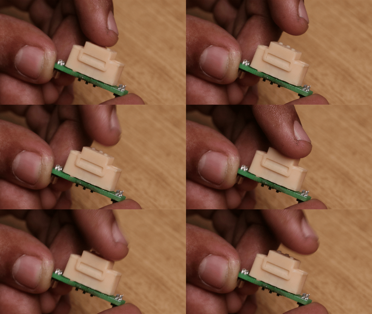
                               Fig. 3 Protruding Force Test


Construction:
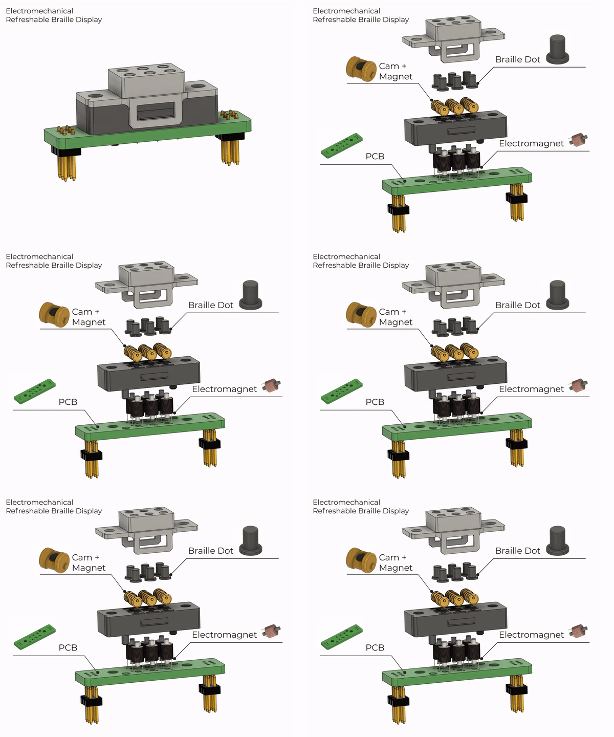
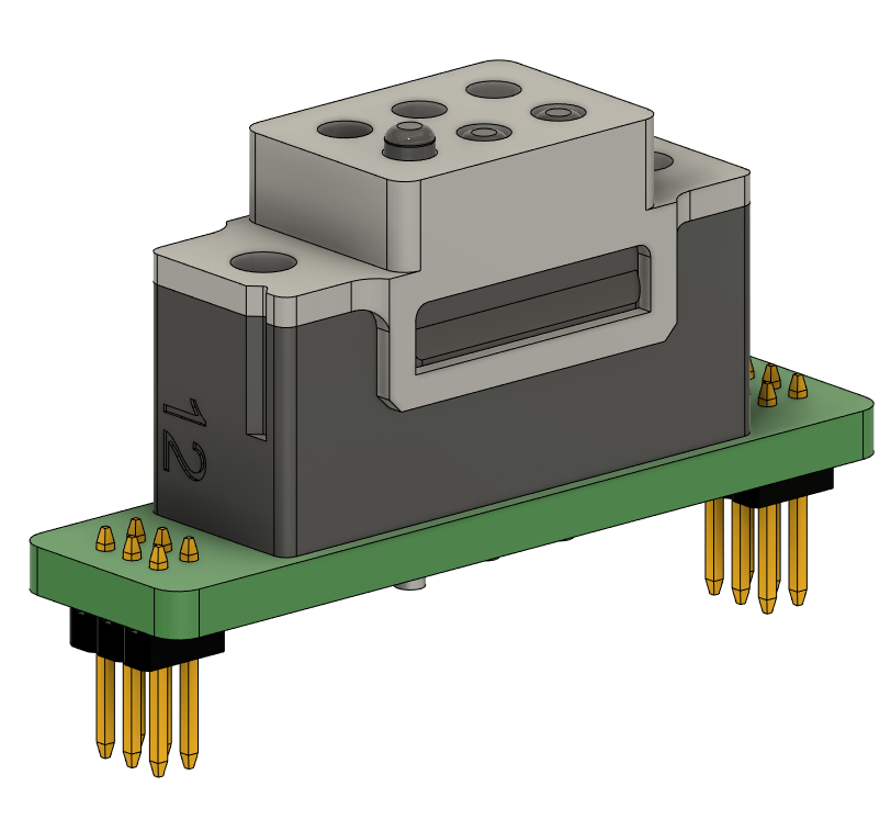
                                                    Fig. 4  Braille Cell Construction

Prototyping is done using a high-resolution SLA 3D Printer as there are many thin-walled sections.
PR4 Resin on a 3D Systems Figure4 machine is being used for its ability to achieve 0.4mm wall thickness. Craftsman resin from Anycubic, on an Anycubic Photon Ultra, was tested to work as well. 
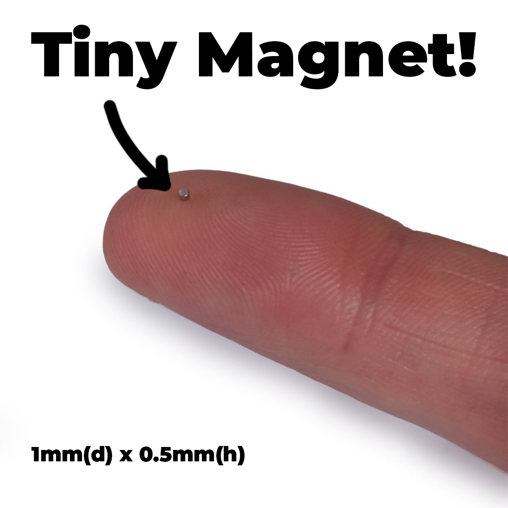
                                                      Fig. 5   Micromagnet

The micro 1mm x 0.5mm NdFeB magnet is what makes this project possible. Luckily there are now a handful of vendors around the world keeping these in stock as they are also used for things like jewelry clasps on thin bracelets, Kingdom Death miniatures, super thing Games Workshop miniatures, and more.
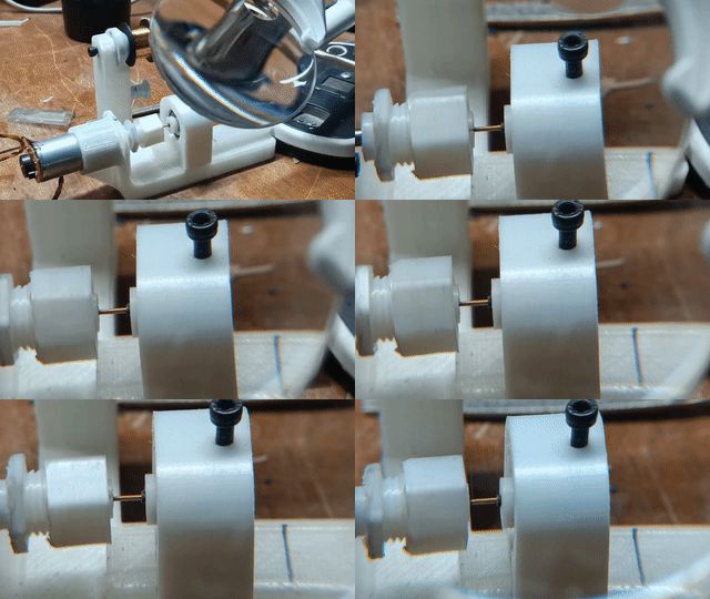
                          Fig. 6 Coil Winding Tool

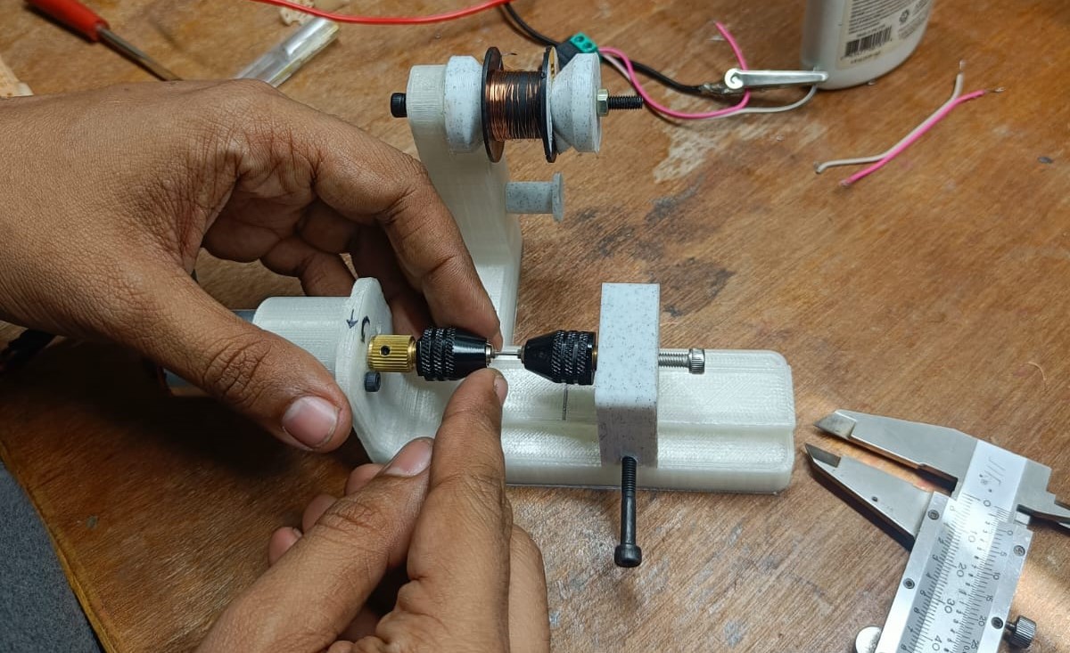
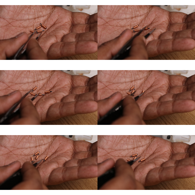
The electromagnets are constructed with 50-micron enamel-insulated copper wire with a ferrite core. A 3D Printed winding tool makes winding such small electromagnets easy. 

Apart from the winding tool, all standard assembly & soldering tools are sufficient to build your own braille modules.
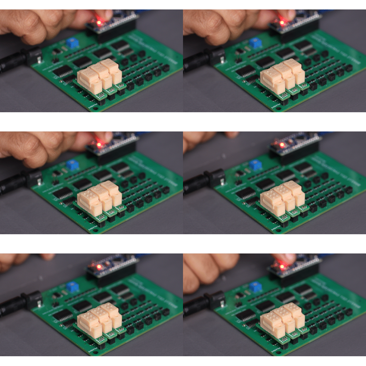
             Fig. 7   Three Dot Array

Up to 3 Braille cells were tested to work together, no reason by more won't work as well. As only one pin is actuated at any time, only 1W of power is consumed at any point of time.

The only drawback of the drive system was that it takes at least 100ms to change the state of one pin, and this stacks up if more cells are added up.  If we were to change the drive electronics so all pins of a single module can be driven simultaneously, then the refresh...

Read more »

Braille Cell V12.f3z

Latest CAD for Braille Cell

f3z - 2.05 MB - 10/10/2023 at 14:08

Download

Coil WInding Tool V2.f3z

Assembly for the coil winding tool used to manufacture the coils needed for the individual dots. Second Version

f3z - 970.05 kB - 10/10/2023 at 13:52

Download

Braille Cell Eagle Library.lbr

.lbr file for footprint and schematic of a braille module for eagle

lbr - 14.22 kB - 09/26/2023 at 16:57

Download

Braille Evaluation Board Eagle Source Files.zip

Eagle BRD and SCH files for Braille Evaluation Board

x-zip-compressed - 102.99 kB - 09/26/2023 at 16:52

Download

Braille Cell Eagle Source Files.zip

Eagle BRD and SCH files for Braille MOdule PCB

x-zip-compressed - 7.32 kB - 09/26/2023 at 16:52

Download

View all 8 files

  • 12th time is the charm

    Vijay10/10/2023 at 14:02 0 comments

    Having access to a printer directly made all the difference when iterating for 20-30 um tolerances. At these sizes, you can't really trust the CAD software anymore, and every assembly has to be empirically tested by printing it out.

    In the final few iterations, I made the Cam assembly with the Braille Lower assembly independent of the Braille Upper, so that I could laser into the hole-shaft tolerance needed between the cam shaft and the hole it fit into. 

    Depending on the Resin, and printer used to print, I suspect the tolerances in the CAD design may need to be altered. Ive linked the final (so far) of the Braille Cell design below for FUsion 360. You should be able to navigate to the design history and change the hole size as needed if the cam is having a hard time fitting, or is too loose. 

    V12 CAD designs can be found here.

  • Updated Winding Jig for Ferrite Cores vs Steel Cores

    Vijay10/10/2023 at 13:30 0 comments

    I was initially using 1mm steel cores harvested from paperclips, but experimentally found that the steel core doesn't take well to fast voltage changes, and heats up the coil so much, that I had a few failures while testing operational parameters.

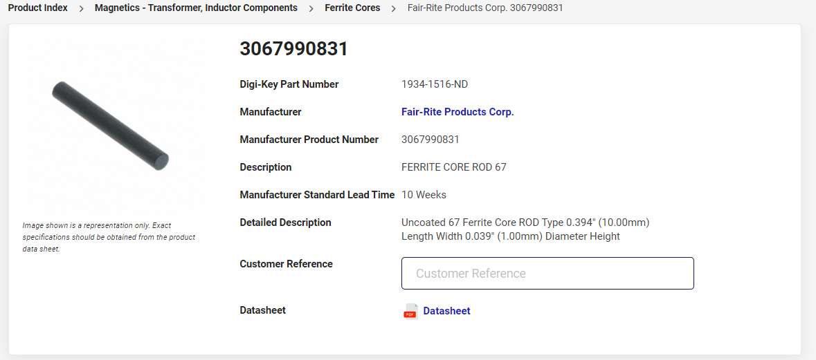
    So I went back to high school science trying to understand magnetic permeability, and properties of soft iron (and WTF is soft iron anyway) and finally found these Ferrite Rods on Digikey:

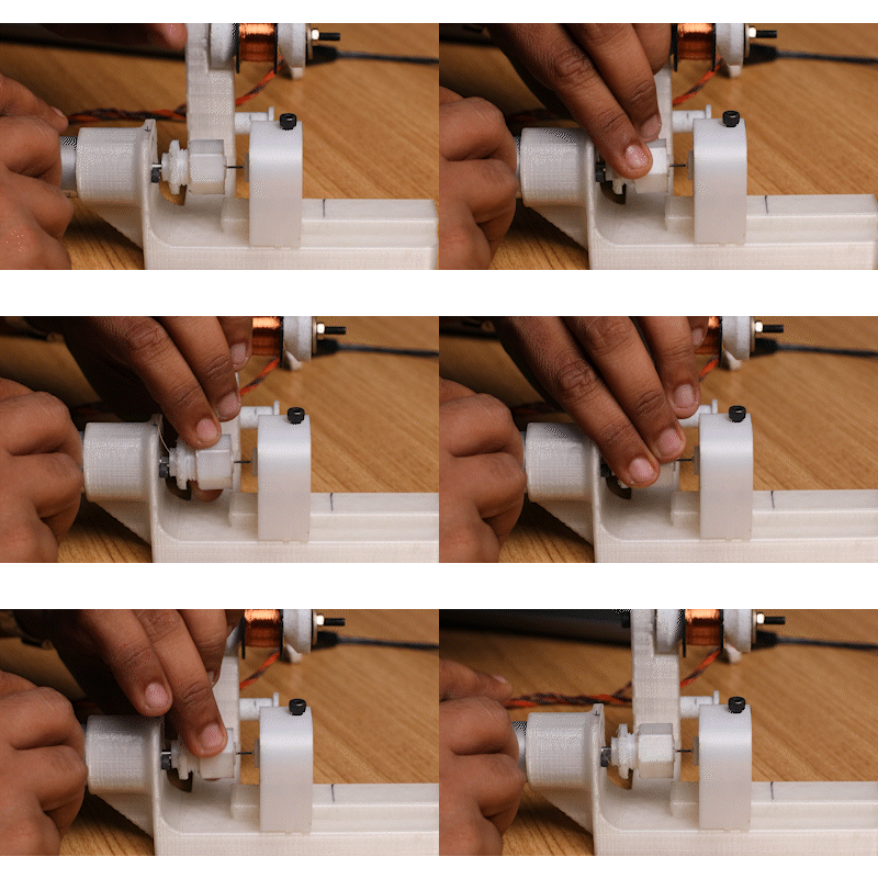
    they turned out to be a lot more brittle and needed more care in assembly. The metal chuck of the first iteration would just snap the ferrite rod. 

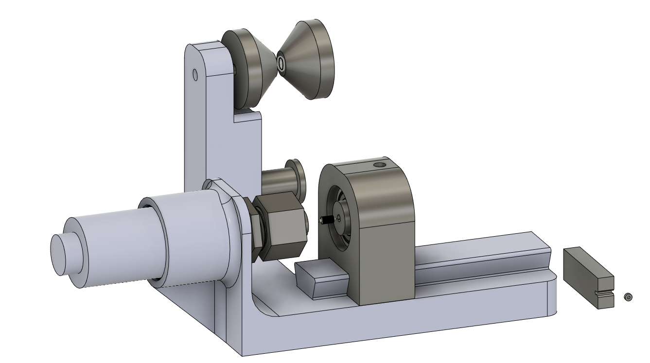
    So I redesigned a complete 3D printed chuck, that IMO works even better than the earlier one, and sits nice and centered

    Ive updated the Instrusions section with details of how to use the new Coil Winding Jig.

    The braille cells made of the ferrite core were found to be:

    • Run cooler & with lesser power requirement
    • Faster max refresh rate,  from 200ms to 50ms
    • Overcomes the issue when the cam magnet is too close to the core, the natural attraction overcomes the opposing magnetic flux, and the cam refuses to flip. the natural magnetic attraction to a ferrite core vs the steel core felt like it was less than half of it.

    THe main drawback of using ferrite cores, however, what that if you are not careful with the winding jig, the core would snap. 

    In the future, I see this process automated, with the same process used to wind small inductors.

    The updated CAD design for the winding jig can be found here.

  • Two dot test

    Vijay10/05/2023 at 15:05 0 comments

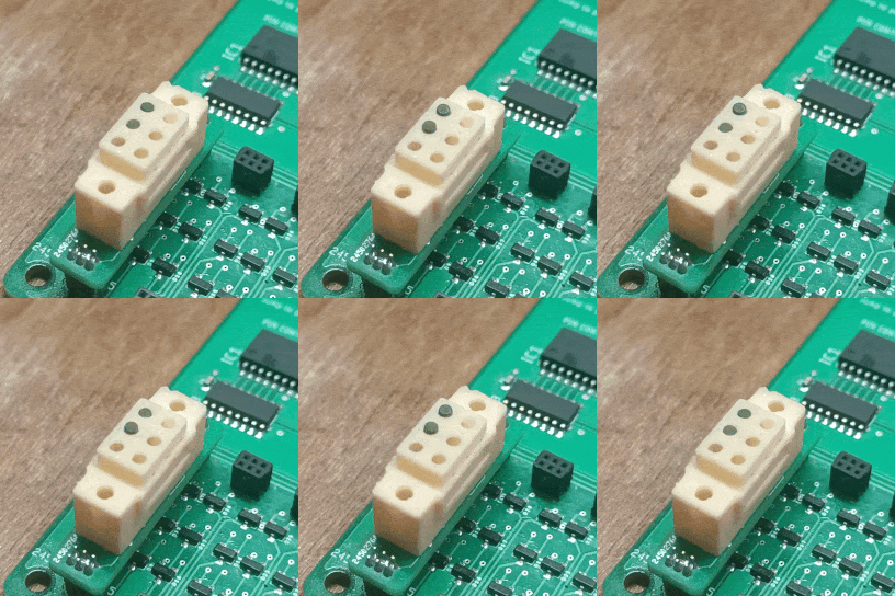
    Two Dots work!! a big achievement, and proves that the concept works as intended.

    A few issues that I want to rectify before assembling the rest of the dots though:

    -Steel core gets TOO hot too fast, it doesn't like too many polarity changes in a short amount of time, which is a big drawback if I'm trying to active fast refresh times. I will switch to a soft iron/ferrite core for the next iteration.

    - Assembly is a real pain in the current version, with the cams wanting to stick to each other before I get the upper and lower halves of the assembly together. Will change over to snap-fit components. 

    -Will move the magnets closer to the center of the rotation on the cams, i.e., reduce the concentricity, to reduce the effect of the cam <sometimes> interfering with the other, but works 80% of the time. 

  • Single Dot Test on PCB

    Vijay10/05/2023 at 14:42 0 comments

    A couple of logs back, we tested the overall mechanism working with a single dot in isolation with the PCB designed and then verified that the PCB boards designed were working with LEDs

    Now it's time to assemble them to see if the designed electronics can successfully drive at least one braille dot.

    And it works! The assembly process for the braille module can be found in the instructions, so check it out there. 

    Read more »

  • Testing Electronics

    Vijay09/27/2023 at 07:35 0 comments

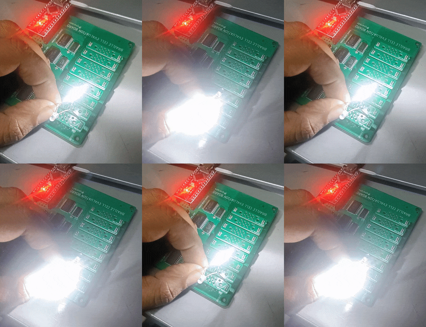
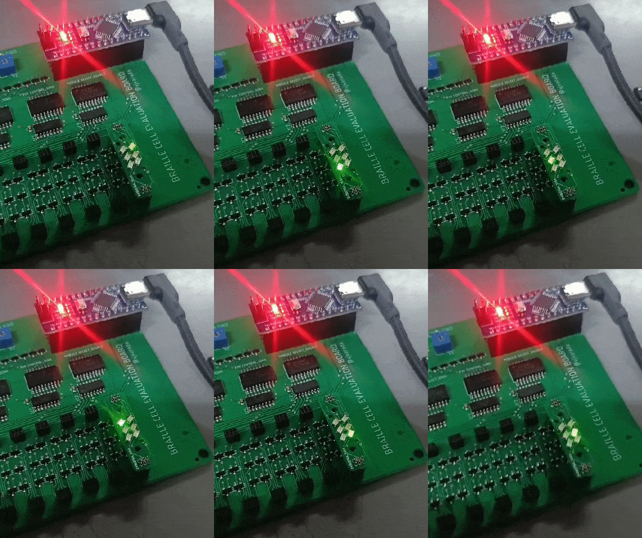
    I tested out the driving electronics using two LEDs connected in opposing polarities, and adjusting the LM317 output to bring down the voltage so as not to burn the LEDs out.

    This is what the code looks like running. The via placement for the coils just happened to be the right size to mount a few 0603 package SMD LEDs, so I converted one of the braille module PCBs into a tester. 

    The code below shows the functions I'm using to select which pin of which module to actuate. MOD_X and PIN_X are the pin numbering for the input pins of the decoder IC.

    Read more »

  • Assembly and Single dot test

    Vijay09/27/2023 at 07:09 0 comments

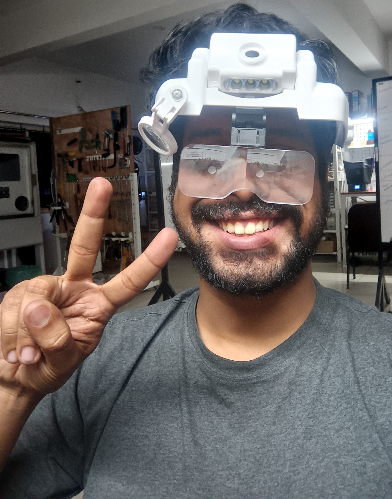
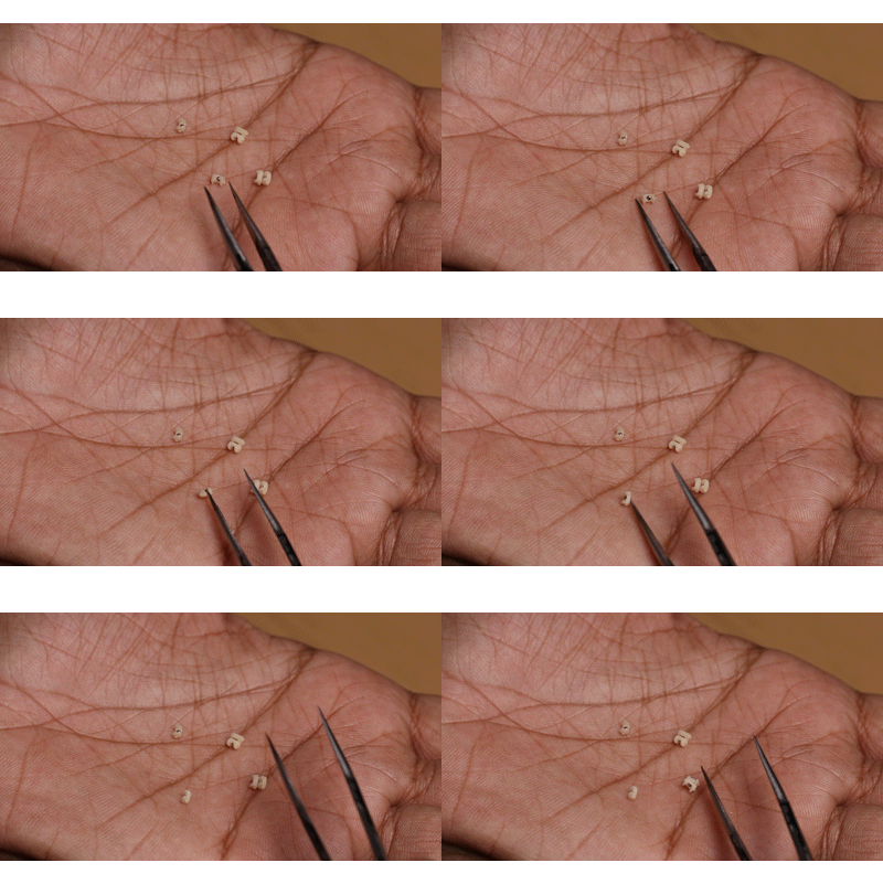
    Assembling such tiny components was proving to be quite tiresome on the eyes, so I decided I'd gear up. I got one of these, and am very happy with the purchase, It's almost like I have superpowers! 

    Read more »

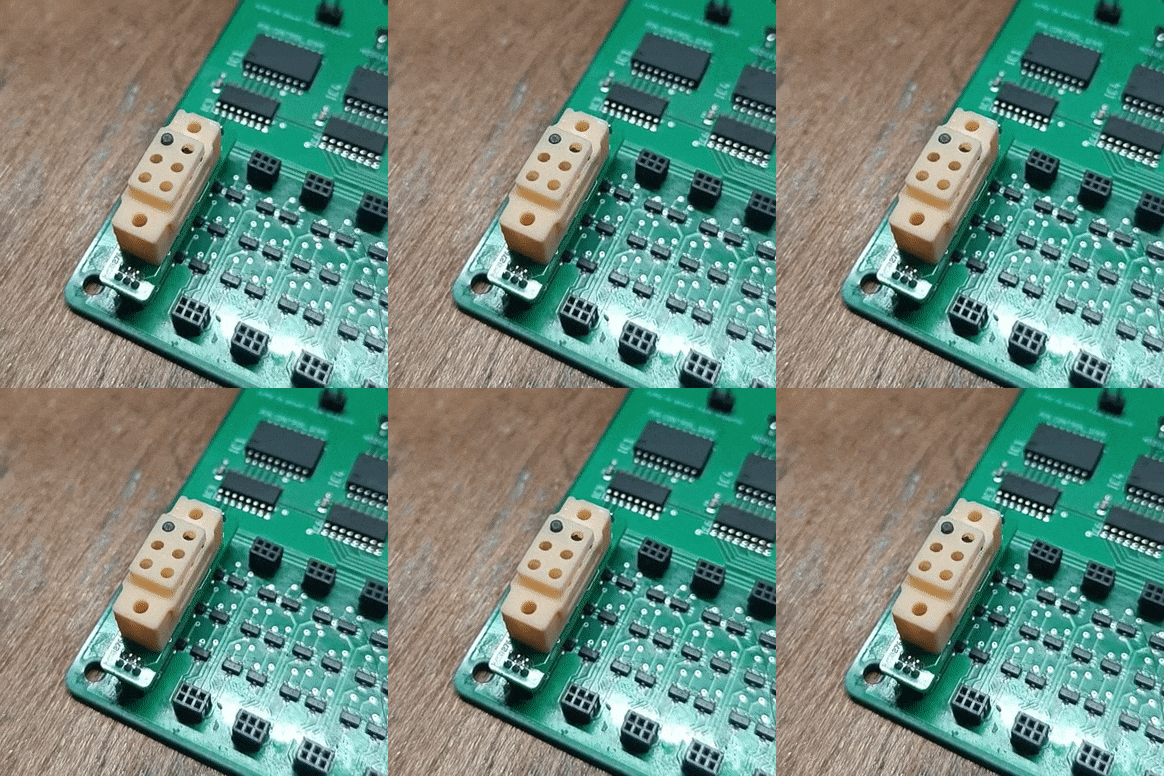
  • 3D Printing: The Devil is in the Details

    Vijay09/26/2023 at 20:21 0 comments

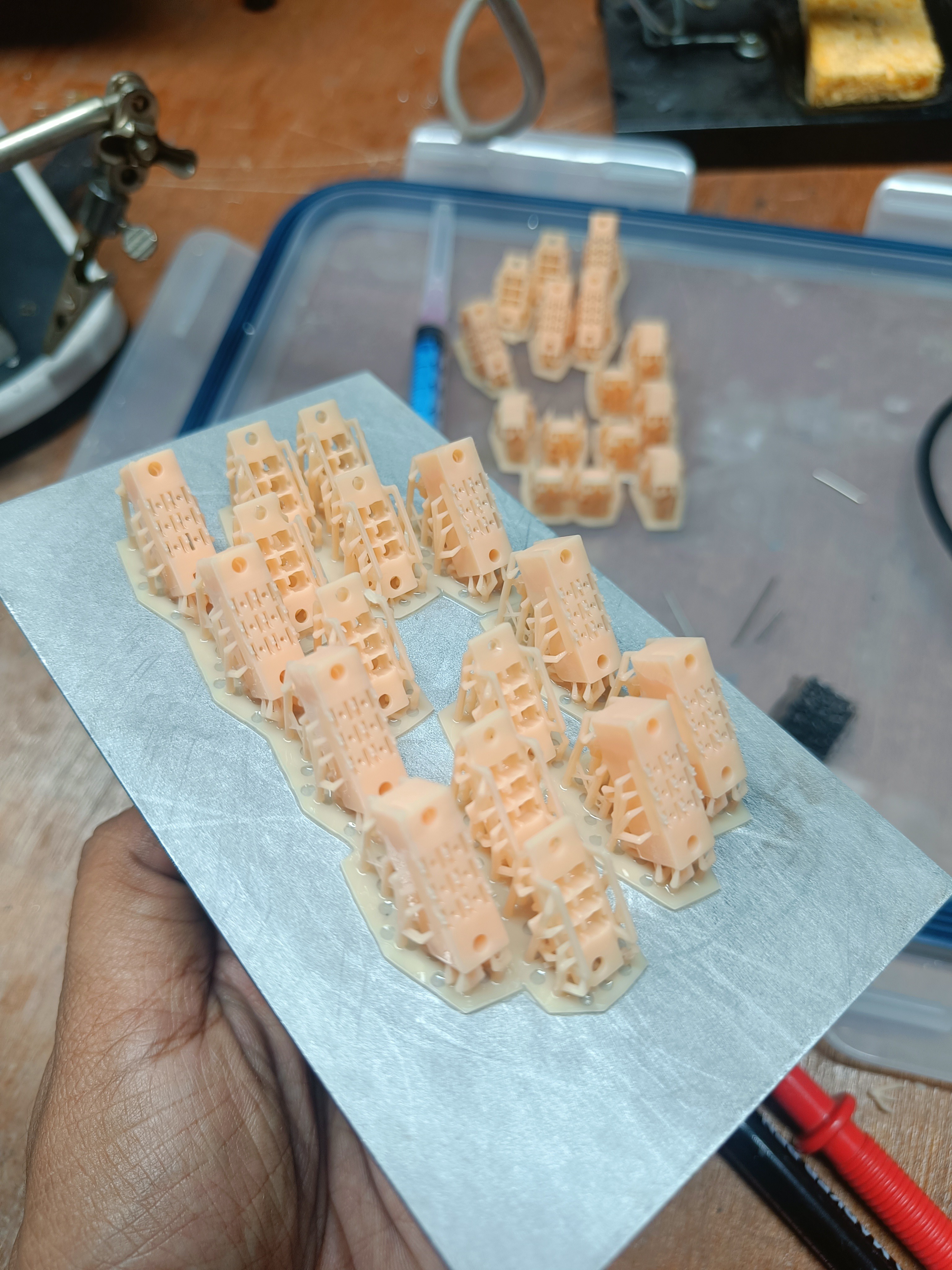
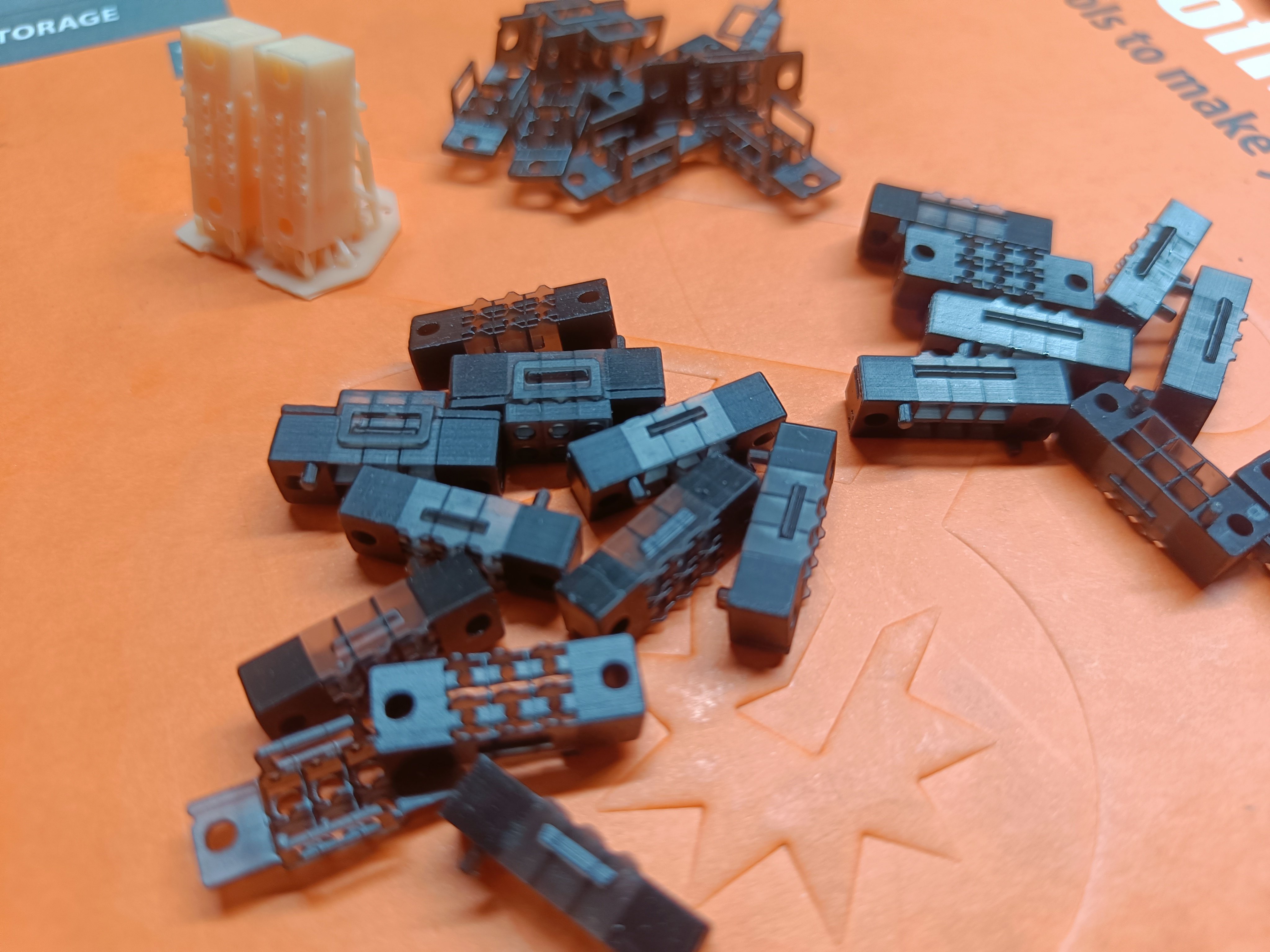
                         Fig 1. Version 3 Braille Parts printed on a Figure4 3D Printer by 3D Systems

    Getting the design right has been a bigger challenge than I initially thought it would be.  I had to go through 7 iterations before things were getting to something that fit together satisfactorily. 

                Fig 2. The various versions of the braille cells printed in SLA in different orientations

    I initially was outsourcing to an external vendor who had a 3D systems figure machine with ProBLK 10 resin that produced pretty strong parts at extremely high detail. Even though I was very impressed at first, I quickly realized that things were either too snug a fit and wouldn't allow for easy motion or that there was too much tolerance and the mechanisms would not actuate predictably. 

    Read more »

  • Braille-Module & Driver PCB's

    Vijay09/26/2023 at 14:21 1 comment

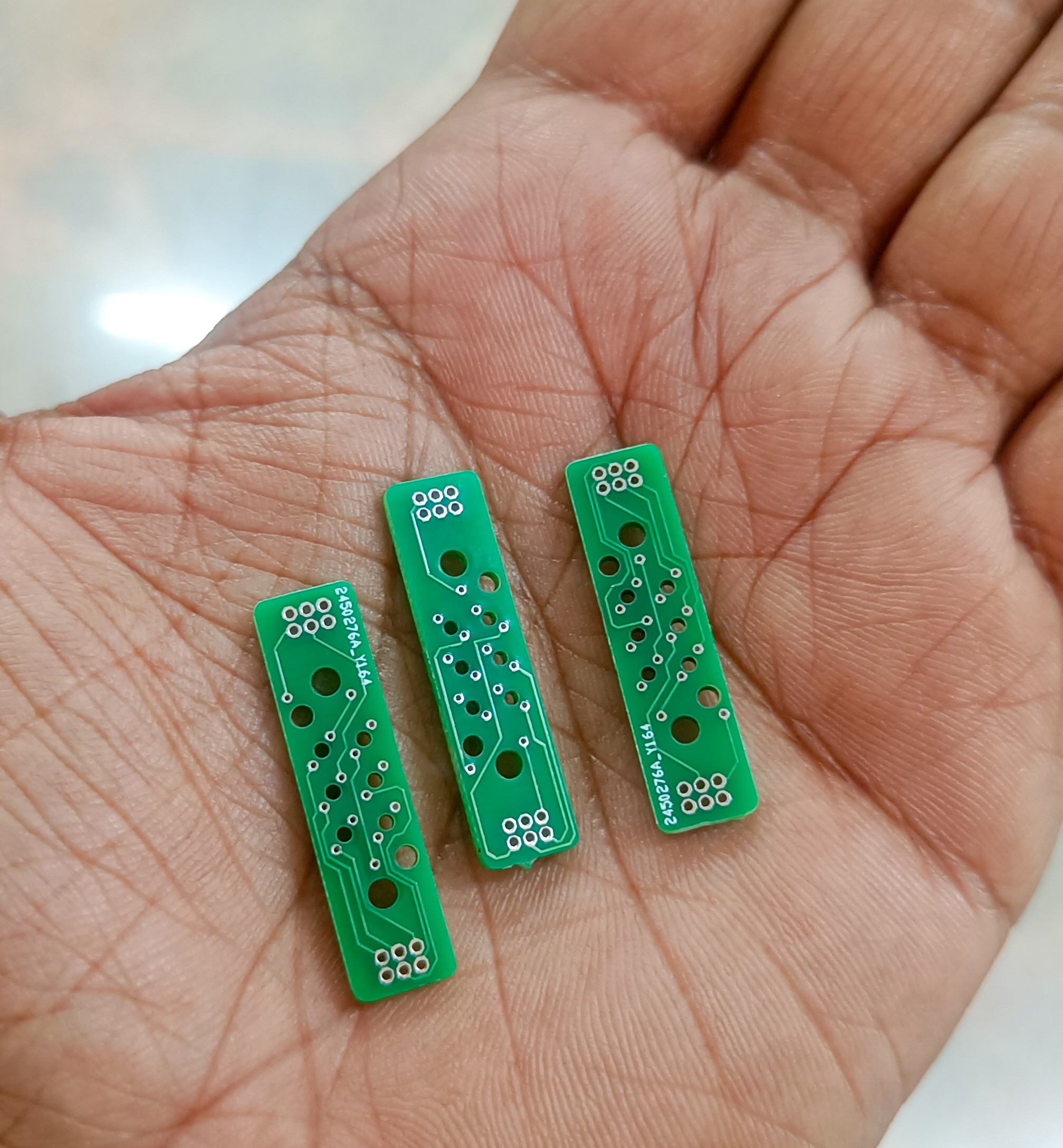
                                               Fig 1: Individual Braille Cell PCB's

    I had to max out the PCB fabs capability and took a few risks in the design by overriding my tried and tested DRC(Design Rule Check) file in Eagle when it came to the distance of the traces to the edge of the board, drills, and pads, but it seems to have worked. Nothing is shorted, or disconnected, so big win! 

    Read more »

  • Coil Winding Tool for Micro-Electromagnets

    Vijay09/25/2023 at 13:01 3 comments

    I figured that the trickiest parts of the build would be the winding of the ultra-small coils, so I designed a coil winding tool to help with this process and make it easier 

    Read more »

  • PCB Design of Braille Cell Evaluation Board

    Vijay09/24/2023 at 13:02 0 comments

    I created an 8 - Braille cell board to evaluate the braille cell functionality. 

    Read more »

View all 14 project logs

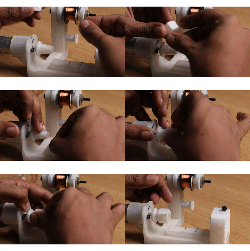
  • 1
    Coil Winding Setup

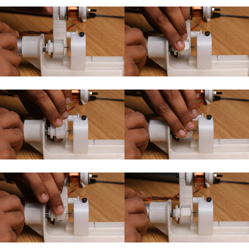
    Step 1 :

    Lock one end of the 50um wire into the groove of the chuck and loosely tighten the chuck tightening screw

    Step 2 :

    Place about 1-2mm of the Ferrite core into the chuck, then with the spacer jig, push the ferrite core in at the exact distance into the chuck using the tailstock.

    Step 3:

    Tighten the chuck to clamp down on the ferrite core, and then remove the spacer and the tailstock

    Step 4:

    Place the 1mm spacer on the other end of the Ferrite core, and gently flush the tailstock to the spacer. Tension the copper wire through the wire guide.

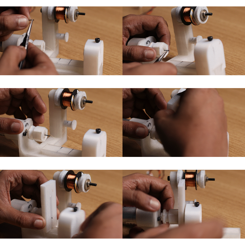
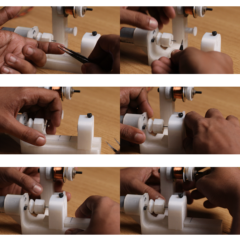
  • 2
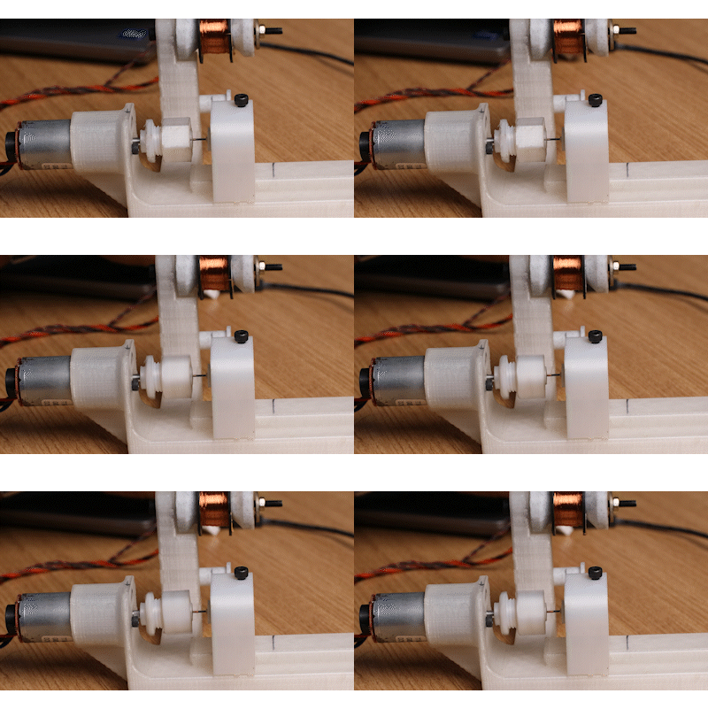
    Winding the Coil

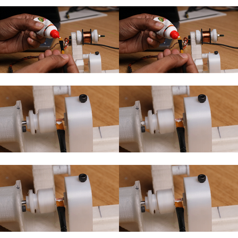
    Step 1:

    Manually wind the first few turns neatly and make sure there is adequate tension in the copper wire

    Step 2:

    Turn on the motor, monitor the coil winding, and guide the coil if required to evenly spread the diameter of the winding.

    Step 3:

    At the end of the winding, using a paintbrush, apply some PVA-based glue to the coil

    Step 4:

    Carefully remove the tailstock, and the spacer. Then loosen the chuck and remove the finished coil. Allow for glue to dry

    Step 4:

    Marvel at the fruits of your labor

  • 3
    Cam Assembly

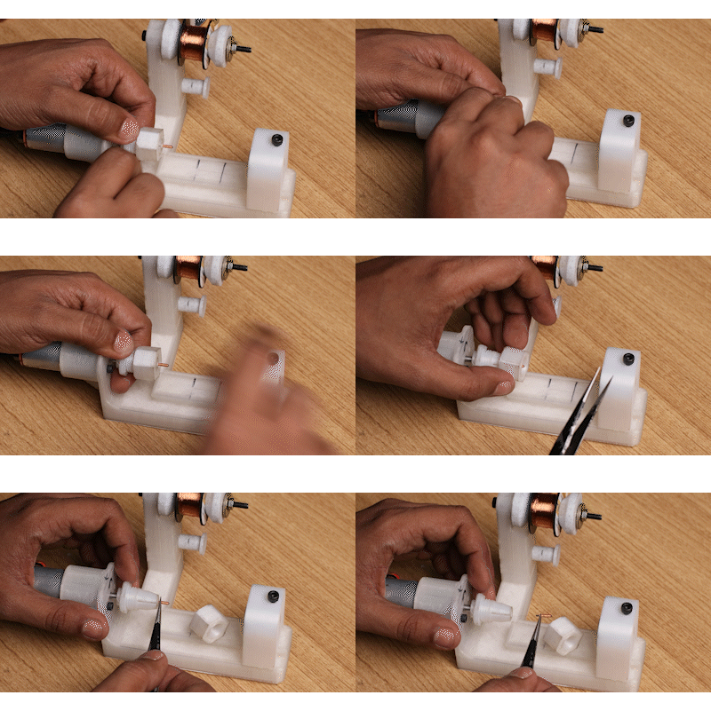
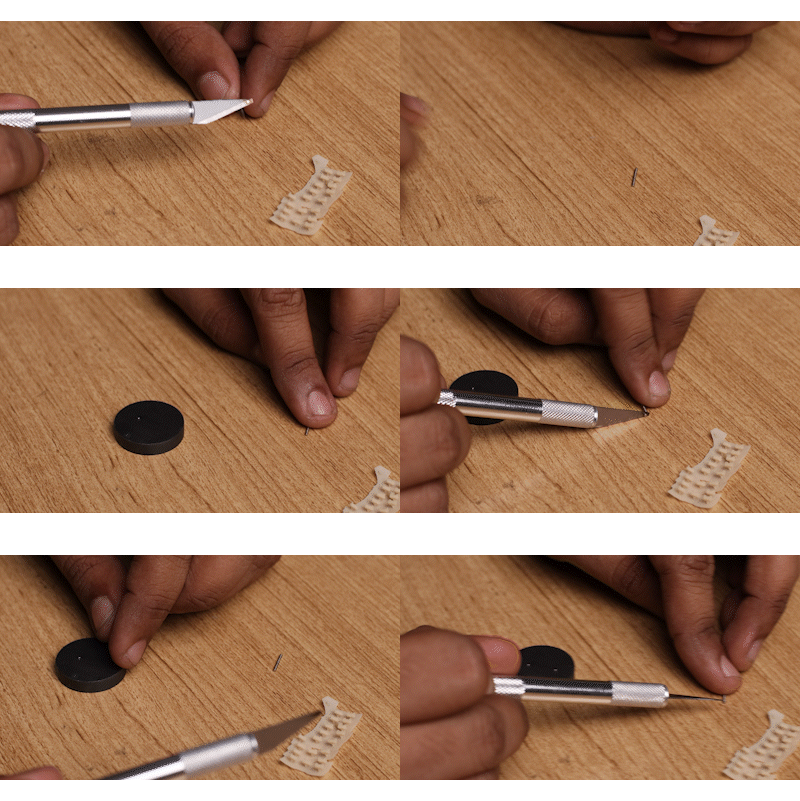
    Step 1 :

    Using a Xactro knife, remove individual 1mm magnets from its stack, and place them on a magnet. Mark a side of the magnet with an identifier, so you can make out the polarity, and hence know the polarity of all the micromagnets. you just need to make sure all are polarised in the same direction. 

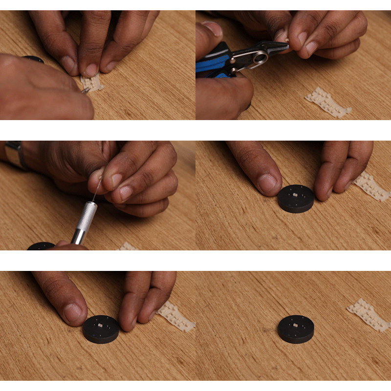
    Step 2:

    Remove a cam from the 3D printed support tree, and clean the area where the support was stuck.

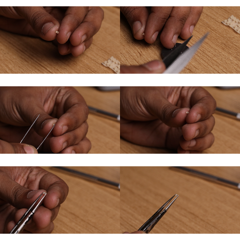
    Step 3:

    Using a tweezer pick up a coil, keep track of the magnetic orientation, and press-fit it into the 3D Printed Cam

    Step 4:

    Marvel at the fruits of your labor

View all 8 instructions

Enjoy this project?

Share

Discussions

xisor wrote 13 hours ago point

Great project!
Can we have more informations about the winding, number of spires/ Value of the coil please?

  Are you sure? yes | no

ahmed Mekhlafi wrote 10/08/2024 at 06:26 point

Can you send me the source files on any other format or any other 3D software, I shows me this message every time I open the files

Initializing document manifest xml stream failed!

The file /Users/ahmedmekhlafi/Downloads/Braille Cell V12.f3z could not be loaded.

  Are you sure? yes | no

zerochi2016 wrote 09/27/2024 at 02:45 point

Hi Mr. Vijay, what company did you use on fabricating your PCB

  Are you sure? yes | no

liul7788 wrote 07/11/2024 at 01:01 point

Good Job! It is inspiring! How do I cite this work? I may extend this in my project. Thanks!

  Are you sure? yes | no

David wrote 06/06/2024 at 18:57 point

Hello,
I have rebuilt your project. It was very exciting until I had all the 3D printing divisions. The choice of filament is also very important. Not every filament is suitable. I also made some changes to the design. It took me 7 months to create an executable prototype. I will continue to develop this further. I didn't have a machine for winding the spool. That's the next thing I'm going to build. Winding by hand is sometimes very difficult.  Many thanks for the inspiration. 

  Are you sure? yes | no

Nikhil wrote 02/12/2024 at 05:57 point

Hey there! Great project. I am working on a robotics project which needs custom electromagnetic actuators just like the ones you made. I am trying to replicate the solenoid coils that you made. Can i please know what was the gauge of the wire, and the length of the coil ? 

  Are you sure? yes | no

Paxton wrote 01/20/2024 at 19:35 point

I love this project, and I was looking to re-create it for myself, however I am currently lacking some information on the BOM. Is there an updated version of the BOM or could I get info about resistor values, potentiometer values, and which capacitor designator goes to which value, as the current BOM has given me conflicting information or none at all. Any information would be greatly appreciated!

  Are you sure? yes | no

Vijay wrote 01/26/2024 at 16:48 point

Hi, sure, where are you stuck? You should have all the information you need in the schematics source files folder. Check out the SCH file if you are stuck to look at the circuit. 

The potentiometer circuit was there to control the amount of voltage I would use to power the coil circuit since I didn't know what value to start with. 

  Are you sure? yes | no

Vijay wrote 01/26/2024 at 16:50 point

The potentiometer/Resistor/Capacitor you are probably referring to is for the adjustable power supply using LM317. I would suggest starting from he schematic first. Im here if you need anything. 

  Are you sure? yes | no

Paxton wrote 01/26/2024 at 17:54 point

I was confused on the capacitances of C1-C6, as the schematic and BOM files were giving me conflicting information. Some capacitors said 9 pF on one doc and 0.1 uF on the other. And for the trimmer potentiometer, I assumed 1,000 ohms but please tell me if it is different.

  Are you sure? yes | no

Vijay wrote 01/27/2024 at 01:03 point

Here are the capacitor values, ive included values in the silk layer of the PCB's as well. Its odd that you are getting different values:'

C1 to C5 0.1uf, C6 is 1uF

Trimmer POT is 0-1k, basically to adjust the resistance for the LM317 ADJ to give different voltage output.

  Are you sure? yes | no

Paxton wrote 01/27/2024 at 03:29 point

I figured that the trimmer POT was 0-1k (thanks google calculators), but thank you for the capacitor values. I have fusion360 but found it easier to work with Altium circuit maker, so I imported the eagle files there. It is quite odd that circuit maker was saying that C6 was 9 pF, as I have no clue where that value came from. I'm looking forward to assembling this project!

  Are you sure? yes | no

hcgilje wrote 12/20/2023 at 10:48 point

Lovely project!
Could you please convert the 3d files to another format than .f3z? it is not supported by any other 3d application.

  Are you sure? yes | no

David wrote 12/21/2023 at 17:31 point

You can download Fusion360 as a trial version and then export your .fz3 file to another format.

  Are you sure? yes | no

Vijay wrote 01/26/2024 at 16:52 point

Since the tolerances in the parts are so critical, I decided to share the source file itself, so you can edit all features directly. As David mentioned, the free license of Fusion 360 is all you need to edit and export files into any format. Within Fusion360 you will also get access to the design history so you can adjust tolerance parameters according to your printer capabilities. 

  Are you sure? yes | no

richsmith0707 wrote 11/30/2023 at 05:07 point

Do you have 'STL' file? the you have uploaded is giving error while opening it.

  Are you sure? yes | no

Razvan T. Coloja wrote 11/14/2023 at 04:52 point

I can't state well enough how much I appreciate your efforts. I have been trying to create an affordable Braille display for years. I've thought of tens of design, from tiny tubes involving air pumps to purely mechanical rotors that would push and keep up the pins. Your design is ingenious, I must say. And keeping the cost of production so low is incredible.
Thank you for making the world a better place.

  Are you sure? yes | no

TRAN.VINH.QUANG wrote 11/11/2023 at 09:00 point

Great job! Could I translate your work to vietnamese and share to our community with original link include ?

  Are you sure? yes | no

Vijay wrote 11/26/2023 at 14:02 point

You are very welcome to! 

  Are you sure? yes | no

Paul McClay wrote 11/10/2023 at 03:15 point

*Table* of contents... Elegant approach to big HaD project navigation. I might be stealing that. And congratulations on your 2023 HaD Prize win!

  Are you sure? yes | no

kelvinA wrote 11/11/2023 at 13:22 point

After seeing this project make a table, and discovering #YGREC8 which writes the logs in a list, I'm also going to pilot-program this too. I'm also going to try writing tags under them, as the titles alone usually don't mention all of the highlights.

  Are you sure? yes | no

Yann Guidon / YGDES wrote 11/11/2023 at 15:15 point

I maintain a formatted list of logs on most of my projects, after 2 or 3 logs, it must be a habit because things can quickly get out of hand :-)
I do this also to help my (now-broken) project downloader/scraper: it's easy to parse with grep/sed/wget.

I wish HaD had this feature to automatically create such a list. Some of my projects exceed the 100 logs and it becomes *very* useful after a while.

  Are you sure? yes | no

kelvinA wrote 01/14/2024 at 14:03 point

I finally implemented the navigation table across most of my projects. Now my title tag system can actually be put to use, where users can CTRL+F something like "[L]" (without quotes) to highlight all E-CAD logs.

  Are you sure? yes | no

Paul McClay wrote 01/15/2024 at 06:40 point

Just checked out some of your project nav tables. That works. It's possible to scan the evolution of a project,and pick logs to read, starting with bold entries. Kudos for methodical pursuit of ambitious ideas.

  Are you sure? yes | no

Vijay wrote 11/26/2023 at 14:01 point

Thankyou! 

IMO Project documentation on HaD should be rethought from scratch. There are so many great projects where it is so easy to get lost in the logs, I hope the log navigation becomes a thing, it's all yours 😆

Would love a similar approach to GitHub Docs where you could add documentation to various sub-systems of a project as you go. 

  Are you sure? yes | no

[deleted]

[this comment has been deleted]

Paul McClay wrote 11/10/2023 at 03:21 point

Great that similar designs are so widely available. Please share some links or search terms.

  Are you sure? yes | no

BRUNO RAFAEL DE OLIVEIRA MARTINS wrote 10/24/2023 at 13:50 point

Man, what you just did is revolutionary! We've been trying to make a viable competitor for the piezo braille cells for years! Congratulations!

I'm not a specialist on the matter, but i believe you can replace the cam mechanism with a bistable compliant mechanism, i'll try to study the subject to contribute to the project! Thank you!

  Are you sure? yes | no

Vijay wrote 10/25/2023 at 02:19 point

Thankyou so much!

Ive been thinking about compliant mechanisms early on, but couldn't figure it out. However, I'm no expert in compliant mechanisms and would love to collaborate 

  Are you sure? yes | no

kelvinA wrote 10/25/2023 at 12:06 point

I'd imagine that a compliant mechanism would achieve the reliability and durability required for the goal of having these braille modules implemented in the outside world (shops / ATMs / etc.).

  Are you sure? yes | no

Trevor Flowers wrote 10/13/2023 at 19:53 point

Excellent work! Would you be interested in switching away from Eagle and Fusion to all open source software so that anyone can use and contribute to the project? OpenSCAD, FreeCAD, and KiCAD are more than capable of working with these designs.
If so, I'm happy to help with the conversion and any questions that come up afterward.
- Trevor (trevor@transmutable.com)

  Are you sure? yes | no

Vijay wrote 10/14/2023 at 11:19 point

Thank you @Trevor Flowers!

I'm always open to using open-source software, but I generally get scared of the associated learning curve, especially since I've invested time in the software I've already taught myself.  However, I'm willing to collaborate to convert the project for use on open-source CAD software for both mechanical design and electronics. 

  Are you sure? yes | no

Blayze Millward wrote 10/23/2023 at 13:49 point

Since your mounting PCB for the electromechanical parts are relatively simple (compared to the other PCBs, at least) and there's a lot of repetition in the physical design, it would probably be possible to put together an OpenSCAD script that generated not only the physical elements, but also the PCB as an SVG for arbitrary sizes of actuator grids. If you take this further, I'd be interested in collaborating (do you have this up on a git repo, or are you just hosting the files here?).

As an aside, just wanted to say that I love this project! I saw it on YouTube, and the ability to hit "like" on this has literally made me make an account with hackaday.

  Are you sure? yes | no

JamesCarron wrote 10/30/2023 at 15:45 point

I'd be happy to help out with the KiCAD conversion eg with review / prototyping etc. I'll reach out @Trevor Flowers 

  Are you sure? yes | no

Trevor Flowers wrote 11/09/2023 at 01:46 point

Hey, I'm caught up in the holiday rush so I haven't had a chance to work on this at all. So, don't let me hold you back! :-)

  Are you sure? yes | no

botmayank wrote 10/11/2023 at 05:46 point

Great work Vijay! All the best for the prize 😁 

  Are you sure? yes | no

Vijay wrote 10/11/2023 at 16:45 point

Thankyou!

  Are you sure? yes | no

Ishaan Pilar wrote 10/10/2023 at 13:18 point

Great project, so fascinating to see the dots move like that! 

What resin & printer did you use to 3D print parts of such accuracy?

  Are you sure? yes | no

Vijay wrote 10/10/2023 at 13:32 point

Thankyou!

Earlier prototypes were made using a 3DS Figure4 printer is PR4 resin. The shin-color parts were printed on an Anycubic Photon Ultra in Craftsman resin.

  Are you sure? yes | no

Josh Joy wrote 10/10/2023 at 13:10 point

👍👏

  Are you sure? yes | no

Vijay wrote 10/10/2023 at 13:32 point

Thankyou!

  Are you sure? yes | no

chiranjeevi wrote 10/10/2023 at 13:02 point

Good job !

  Are you sure? yes | no

Vijay wrote 10/10/2023 at 13:09 point

Thankyou!

  Are you sure? yes | no

Similar Projects

Does this project spark your interest?

Become a member to follow this project and never miss any updates