 Andy Nicol
-
1Acquire a USB amplifier/ADC sound interface
This example uses a Behringer U-PHORIA UMC202HD for the NMR receiver system, it provides a very low noise amplifier, and a 192kHz 24-bit ADC, powered by 5V USB. It is widely available for around $100 USD. The similarly priced Native Instruments Komplete Audio 2 seems to perform the same, but has not been tested extensively.
The UMC202HD used for the development of this project seems to remain fully functional after thousands of polarization cycles, with no external protection diodes in place.
https://www.behringer.com/behringer/product?modelCode=0805-AAI
Recommended (free to download) software:
For Windows - SDR# by Airspy
A PC laptop can power the UMC202HD directly. However, in some cases, it may be beneficial to operate the interface using an external USB power bank. The UMC202HD is provided with a double-ended USB cable that enables connection to an external power supply.
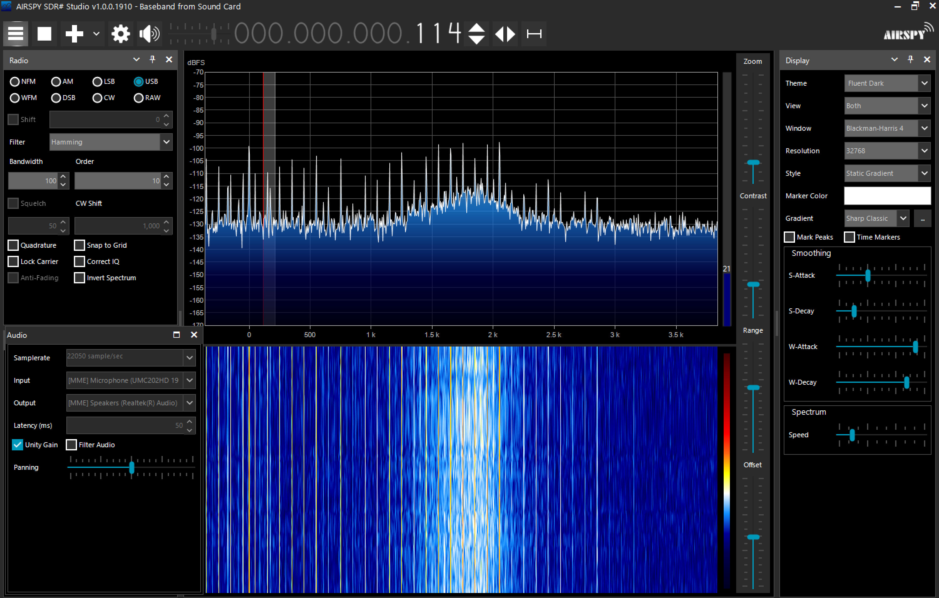
SDR# should be set up as shown in the image below.
Radio should be set to USB
Source should be Baseband from Soundcard
In the Audio settings panel, 'Input' should be from the UMC202HD
![]()
For ios: Spectrumview by OxfordWaveResearch available on the App Store
Running a UMC202HD from an older iPhone requires a 'Lightning to USB Camera Adapter', and an external USB battery to power the interface.
Start by opening the Spectrumview app and initiating the spectrogram with the phone's mic as the default source. Power up the interface by plugging one end of the double-ended USB cable into a USB power source. Then, connect the other end of the USB cable to the camera adapter. The software should automatically recognize the interface and set it as the active source.
The video below measures the noise performance of the UMC202HD and other audio interfaces of the same type:
-
2Build the spool
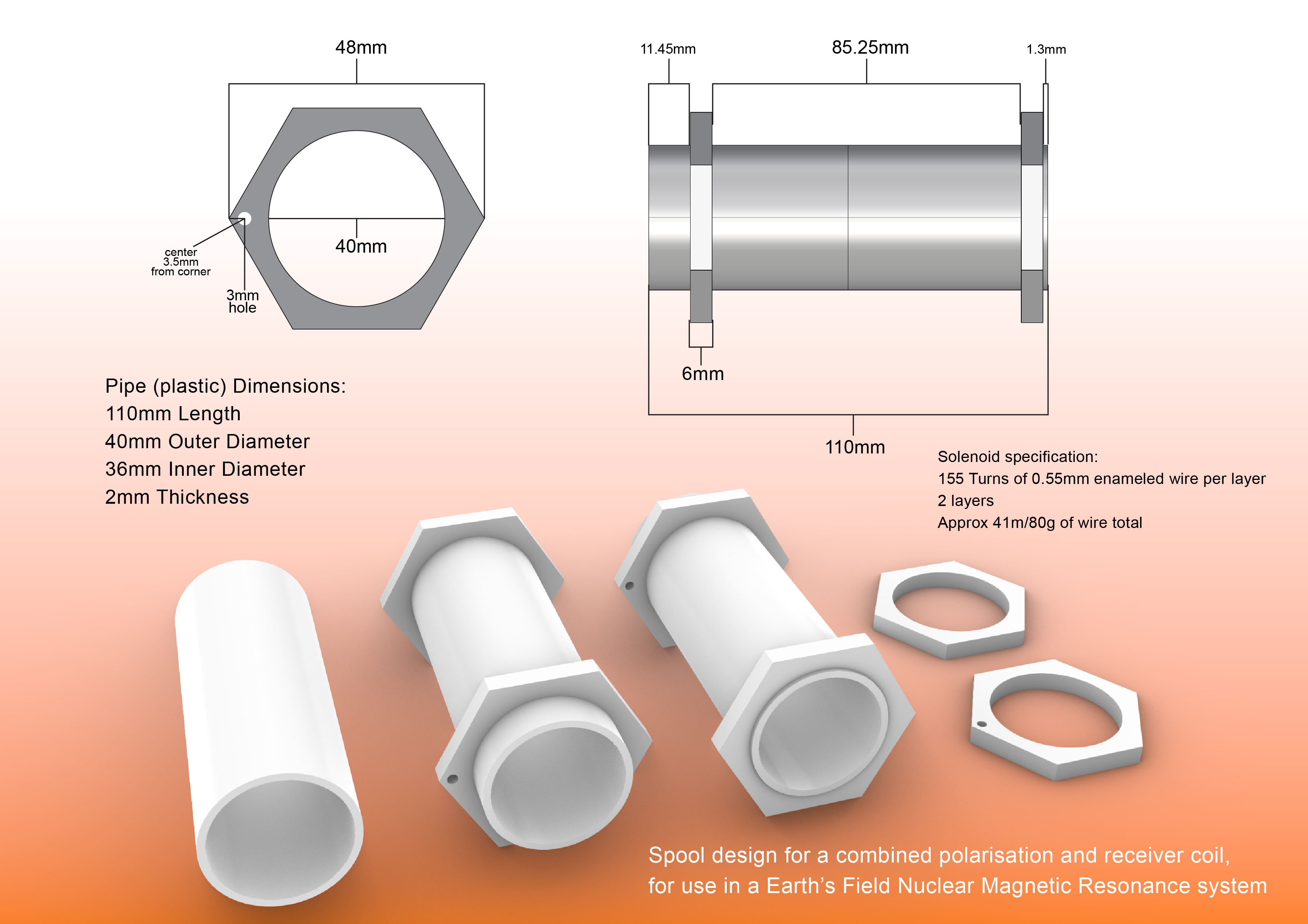
The dimensions of the spool are not critical. Larger or smaller spools should work similarly. An exact wire length is not important. Coils with more layers might perform better. This spool was designed to be as minimal as possible, to make it easy to slot into shielding or additional solenoids.
The maximum sample volume is approximately 60ml. This coil can detect a signal using a water sample volume of 25ml, and it might be possible to use even smaller volumes. Although a 50ml centrifuge tube is slightly too long for the demonstrated coil, it is a good sample holder and is widely available.
The spool in the videos used two 3mm thick pieces of ABS, laser cut and glued together to make each 6mm end piece.
The end pieces were glued to the tube using cyanoacrylate.
You need:
1 x 110mm of plastic pipe, 40mm OD, 36mm ID, 2mm wall thickness
Some material for the end pieces
![]()
A 3D printable STL file of the above spool is available here:
https://cdn.hackaday.io/files/1911928179958528/EFNMR-coil-3D-printable.stl
A pdf of the above image is available here:
https://cdn.hackaday.io/files/1911928179958528/EFNMR-spool.pdf
-
3Wind the coil and attach the XLR cable
You need:
24 AWG Enameled Copper Wire. At least 41 meters or 80g
2 meter XLR microphone cable with one M connector (24AWG/0.5mm core)
A soldering iron and some solder
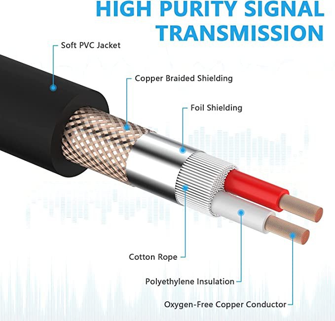
Ensure that the XLR cable body does not contain any magnetic material. You can check this using the compass/magnetometer in a smartphone or a magnet. Any steel in the wire will disrupt the signal. You are looking for a cable with a core as pictured below, in 24AWG or larger diameter wire. Stranded or solid core wire is acceptable.
![]()
Winding Instructions:
Maintaining constant tension on the winding wire and preventing the feeding spool from running freely are crucial for successfully winding a coil. The feeding spool requires some kind of tuneable friction, and the wire needs a spring or weight to maintain tension. Once this part is set up properly, rotating the spool in your hands to wind it becomes simple.
Construction stages:
Thread one end of the enameled wire through the inside of the hole at one end of the spool.
Clamp this end to the section of the tube on the outside of the spool using a cable tie, removable hot glue, etc.
Begin winding the coil in your preferred direction, clockwise or anti-clockwise.
Apply a few drops of cyanoacrylate glue on top of the wire after a couple of turns to prevent it from running freely. If you need to pause winding for any reason, you can use cyanoacrylate to secure the wire in place and prevent a loss of tension if the coil is moved.
Maintain moderate tension on the wire, manually pushing each new turn against the previous one as needed. The top layer should sit on top of the indents of the lower layer, so it's important that there are no gaps in the lower layer.
The coil should be continuous like a standard solenoid. Wind all the way to the other end of the spool, move up a layer, then come back in the opposite direction. This creates a two-layer coil design.
Once you've returned to the starting side, glue the final turns to maintain tension in the coil.
Feed the end wire through the hole.
Cut both ends of the enameled wire at the hole. Ideally, everything should be fixed in place by the cyanoacrylate.
Detach the initial clamp from the spool and discard the cut wire.
Strip the XLR wire and expose 14mm of the inner two coated wires (14mm is the distance to the spool hole).
Clamp the end of the XLR cable to the pipe using a cable tie. Ensure the tie is tight as this will provide strain relief for the coil. Consider gluing the XLR cable to the pipe for additional strain relief.
Feed the XLR wires through the hole.
Remove the enamel coating from the coil wire ends.
Finally, solder the XLR wires to the coil wires.
-
4Build the control box
Any of the components for the control box can be exchanged for another part. The Behringer sound interface has an input port for 1/4" connectors as well as XLR. A three state (on1,off,on2) switch is recommended as the off state is often useful for troubleshooting. The switching tuner is optional, but some tuning capacitors across the receiver lines are required in most circumstances.
For the design in the images below you will need:
100x68x50mm Junction/Project Box
Available widely in various materials. A transparent lid is more informative. A 3D printable version can be found at the bottom of this section.
0.5-1 meter XLR microphone cable M/F
3-way XLR. Any cable length, smaller is better. Connects the control box to the amplifier
XLR socket panel mount F
3 Holes
XLR socket panel mount M
3 Pins
Panel mount battery connector XT60
Or XT30, XT60 to XT30 conversion cables are available
3 Way Rocker Switch 10A/125V (on1,off,on2)
Any type, example uses a snap-in switch with a round button
3 x Spade connectors
For the 3-way switch pins. Solder wires to the spade connectors to avoid heat damaging the switch
8 way DIP switch
For the tuner. Each switch selects whether a capacitor is connected to the receiver line
53.3mm x 53.3mm strip board
No PCB required! Strip board is sufficient for the tuner
2 x 2.54mm Pitch 8 Way 1 Row Straight SIL Socket Strip
Two rows, one for each leg of a capacitor in the tuner
24AWG general wire
Solder this to the connectors
4 x (M3 x 10mm) self tapping screws
To attach the tuning board to the case
4 x (M3 x 10mm) screws with nut
For the XLR sockets
2 x (M2.5 x 10mm) screws
For the XT60 socket which should come with an inbuilt nut
A step drill bit is an economical way to drill the larger holes in the case
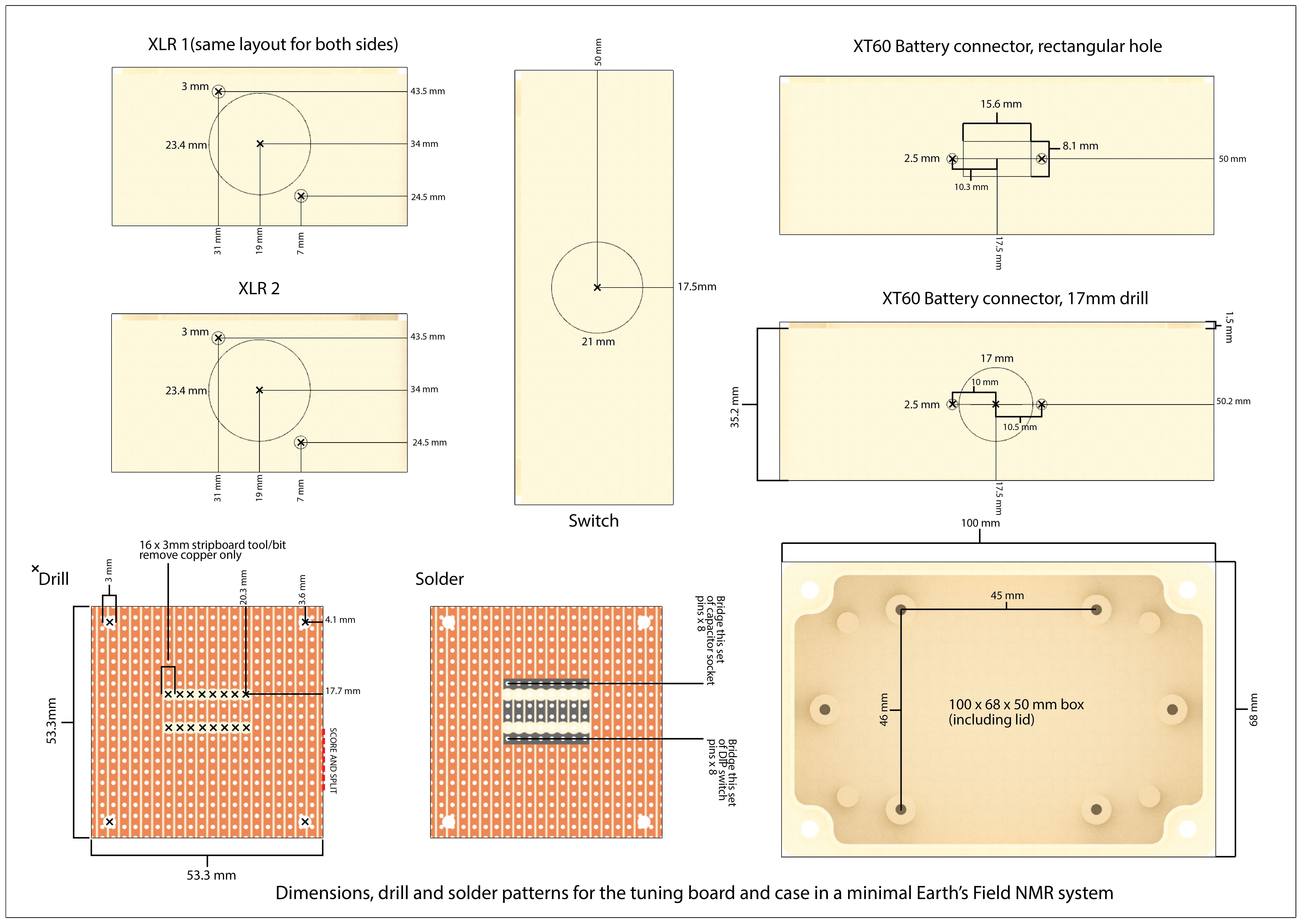
The XLR and XT60 sockets can be soldered with 24AWG wire directly, but you should find suitable spade connectors for the switch. Solder or crimp to the spade connectors, then slot them on the switch terminals.
![]()
A pdf of the above image is available here:
https://cdn.hackaday.io/files/1911928179958528/EFNMR-wiring-diagram-and-schematic.pdf
![]()
A pdf of the above image is available here:
https://cdn.hackaday.io/files/1911928179958528/EFNMR-plans-dimensions-drill-solder.pdf
A 3D printable STL file version of the control box is available here:
With holes - https://cdn.hackaday.io/files/1911928179958528/EFNMR-case-main-body-with-holes-3D-printable.stl
Without holes - https://cdn.hackaday.io/files/1911928179958528/EFNMR-case-main-body-without-holes-3D-printable.stl
The lid - https://cdn.hackaday.io/files/1911928179958528/EFNMR-case-top-lid-3D-printable.stl
-
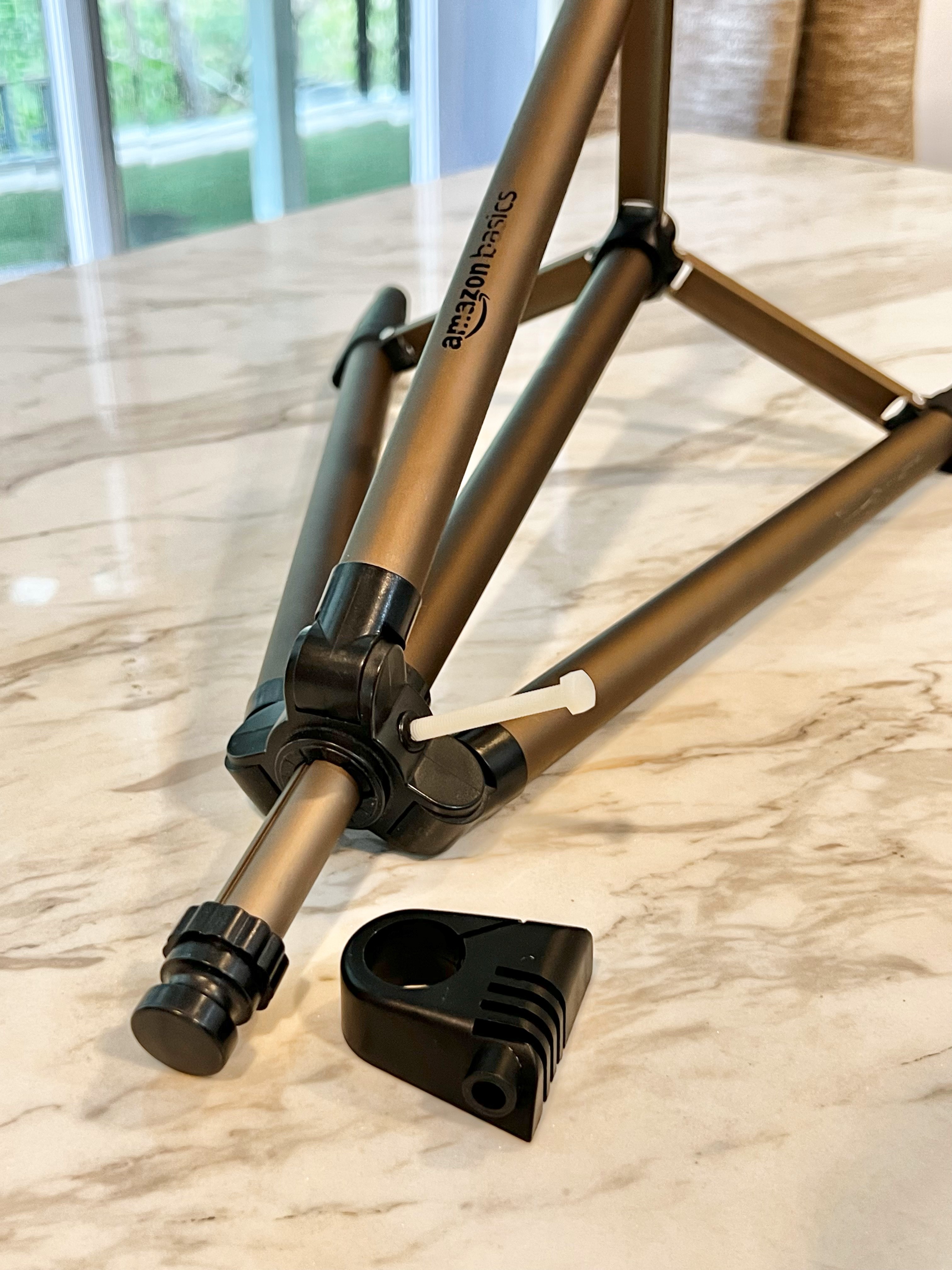
5Modify the tripod and attach the coil
You will need:
Amazon Basics 127cm (50") Lightweight Tripod
This tripod is less than $20 USD, it is also widely available from OEM brands on Aliexpress etc
3 × (M3 x 10mm) nylon screws
Three to replace tube screws in the tripod, anything non magnetic will do
1 × (M5 x 20mm) nylon bolt
To replace the vertical adjust bolt. Needs enough length to grip with fingers
2 × Cable ties
One for cable strain relief, one to attach the coil to the tripod
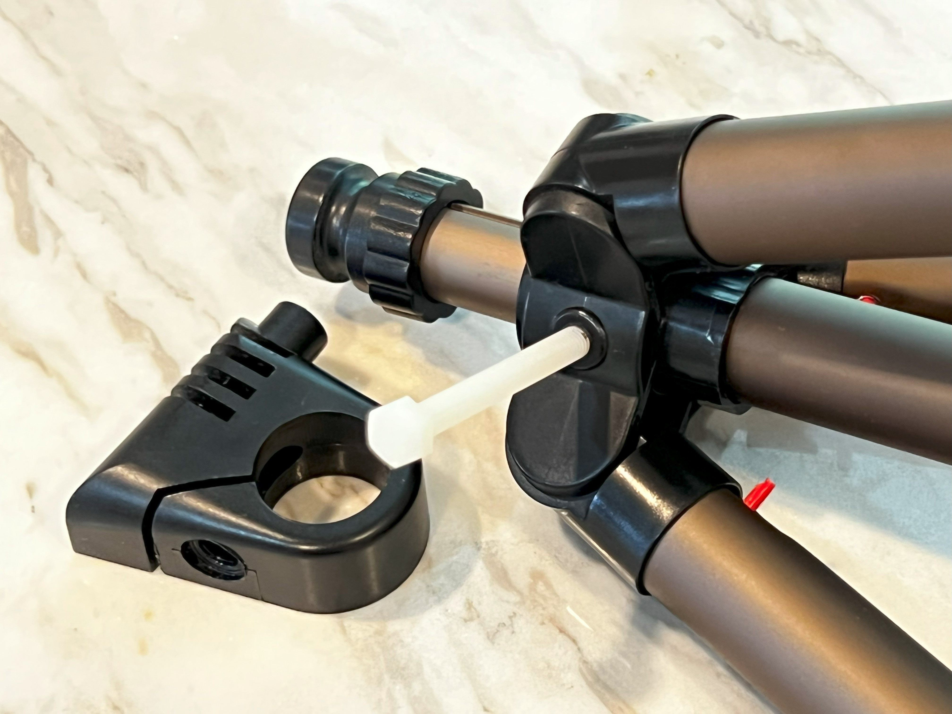
This tripod is primarily composed of aluminium and plastic, so only a few alterations are required.
The central plastic body contains three ferromagnetic screws that need replacement. The location of these screws is indicated by a red stick in the photograph. To access the screws, the central aluminium tube must be unscrewed from the central plastic body. This central body features an M8 plastic thread on its side, and it comes with a metal adjustment bolt. However, this bolt can be substituted with an M8 nylon hex bolt, which can be easily adjusted by hand.
Except for the plastic piece that clamps to the head of the top tube, discard everything from the tripod head. This piece needs a metal nut removed. The clamp should already be sufficiently tight to maintain the coil steady at a specific angle, but if needed, the nut and bolt could be replaced with nylon counterparts.
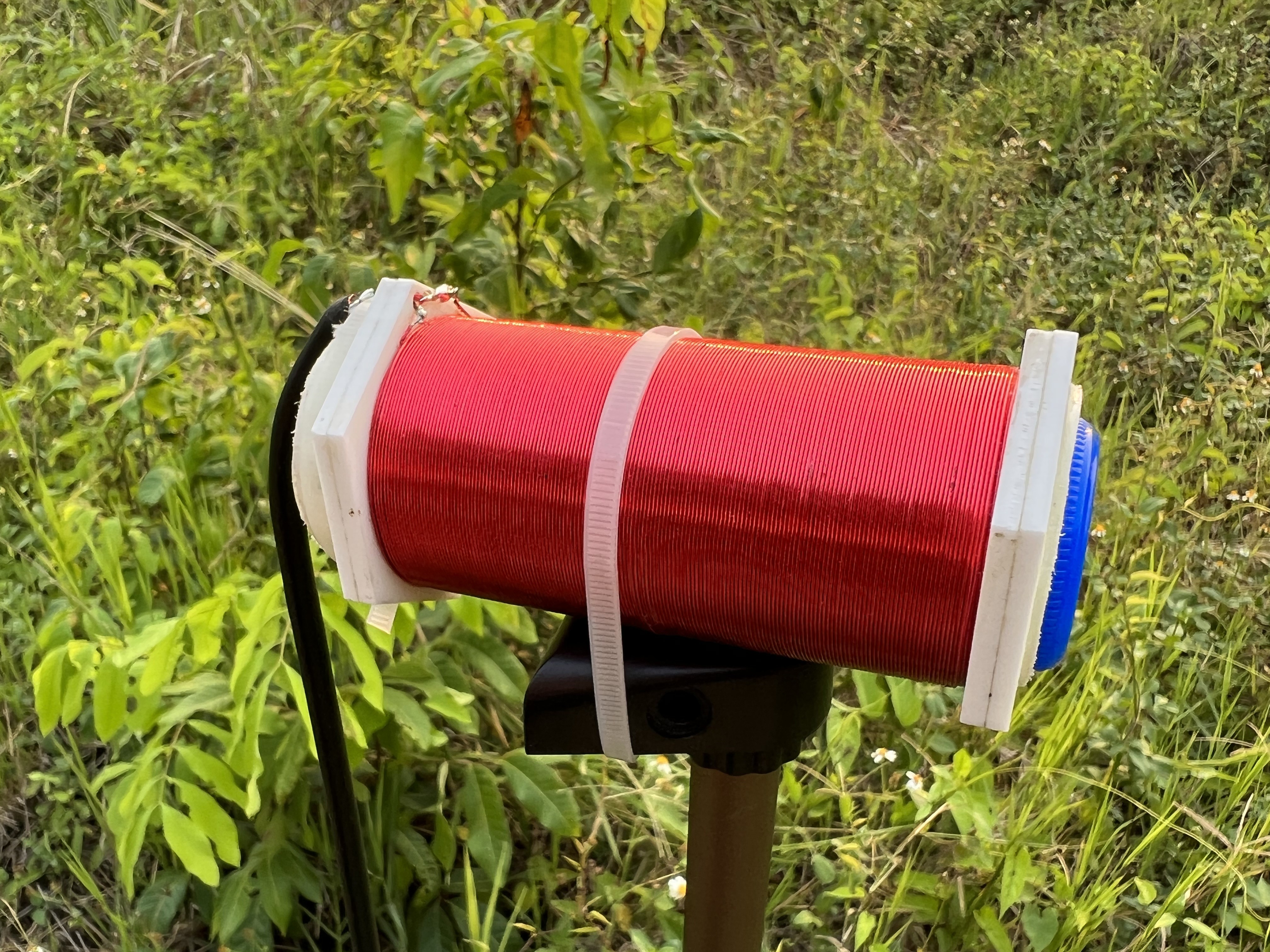
Once the tripod head piece is snapped onto the top tube, mount the coil to the head using a cable tie or something similar. The coil can now be rotated 360 degrees.
![]()
![]()
![]()
-
6Test the reception of the coil
First, plug the coil into the control box, then plug the control box into the USB amplifier input port. Switch the control box to 'receiver' mode. Insert a non-polarized capacitor, with a value between 0.5uF and 1uF, into the tuner socket, and toggle the corresponding dip switch to the 'on' position.
Now we need to estimate the precession frequency of hydrogen at our current location, so we use a known value for the local field strength.
Either use the magnetometer/compass in a smartphone to measure the total local field strength, or, look up a value for your location from the geomagnetic models at:
https://www.ngdc.noaa.gov/geomag/calculators/magcalc.shtml#igrfwmm - Select the 'Magnetic field' tab and use the 'total field strength' value.
Then, calculate the local Larmor frequency of hydrogen, which is given by:
f = γB / 2π
Where:
f is the Larmor frequency
γ is the gyromagnetic ratio for hydrogen (approximately 267.513 million radian/second/Tesla)
B is the magnetic field strength in Tesla
2π is a constant
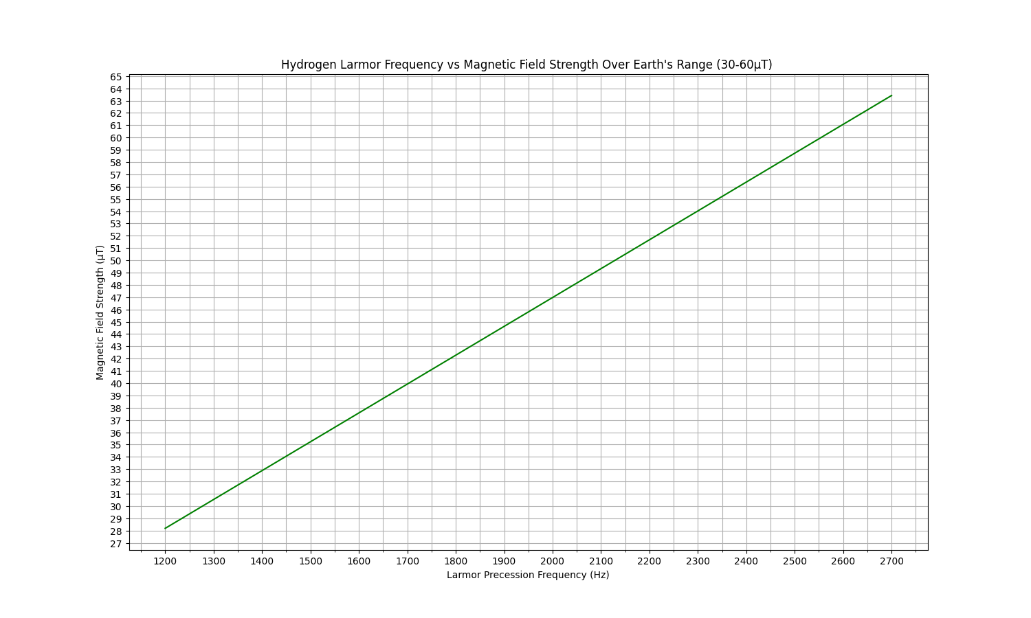
Or use the graph below to look up precession frequency for a given field strength:
![]()
Once we have our estimated local frequency, we need to create an artificial signal on the coil using a sine generator. This can be easily done with a smartphone. Download a function/tone/frequency generator app, ideally one that includes a sweep function.
Set the range of the sweep function around the estimated precession frequency, e.g., if the precession frequency is 1900Hz, set the range to approximately 1800Hz to 2000Hz.
Start the receiver/spectrogram software and ensure that the switching box is operating in receiver mode. Set the amplifier gain to a level between half and full. Configure the buttons for the channel as follows: INST should be pressed/in, and PAD should be not pressed/out. All other pots should be turned down. The Direct Monitor function should be disabled.
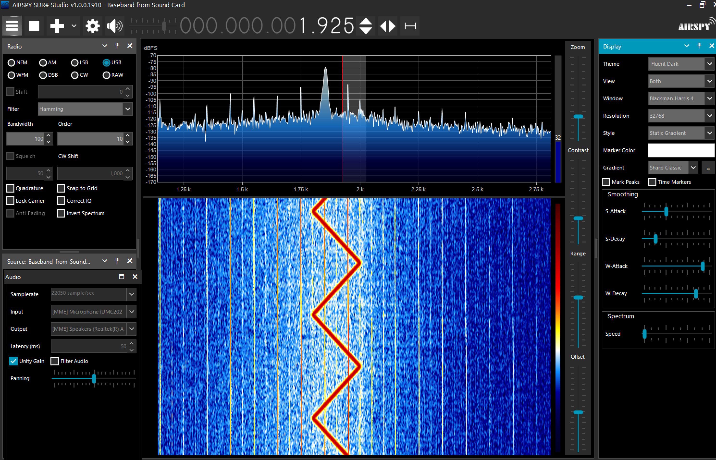
With the volume turned up, wave the signal generator (or phone) around the coil. The electromagnetic radiation from the speaker system in the phone will be easily picked up by the coil in certain positions. The spectrogram software should display a pattern over the range of the sweep function.
As pictured in SDR# with the sweep function in 'bounce' mode between 1800Hz and 2000Hz :
![]()
-
7Tune the coil
Now that the coil and software have been confirmed as functioning with a strong artificial signal, the coil should be tuned to resonance using capacitors in order to be sensitive enough to detect the hydrogen signal. Expect capacitance values to range between 0.5uF at the high field end and 2uF at the low field end.
Insert a variety of capacitors into the sockets in the control box, and toggle the dip switches on and off while monitoring the spectrogram software. As depicted below, a tuned coil should produce a distinct intensity spot in the graphs, over a total range of approximately 300Hz. Increasing the capacitance will shift the resonance to the left, while decreasing it will shift it to the right.
Aim to align the peak of the intensity spot with the predicted Larmor frequency.
The image below demonstrates a tuned coil using 1.34uF of capacitance, achieved by using three parallel capacitors, optimized for a local field around 45uT.
![]()
-
8An additional test
This stage is optional but can be useful for troubleshooting.
Once the coil is tuned, we can artificially test whether both the system and local noise will allow for the detection of a signal. This test can also be used to check an unverified amplifier or to test new system modifications without the need to set up a hydrogen experiment.
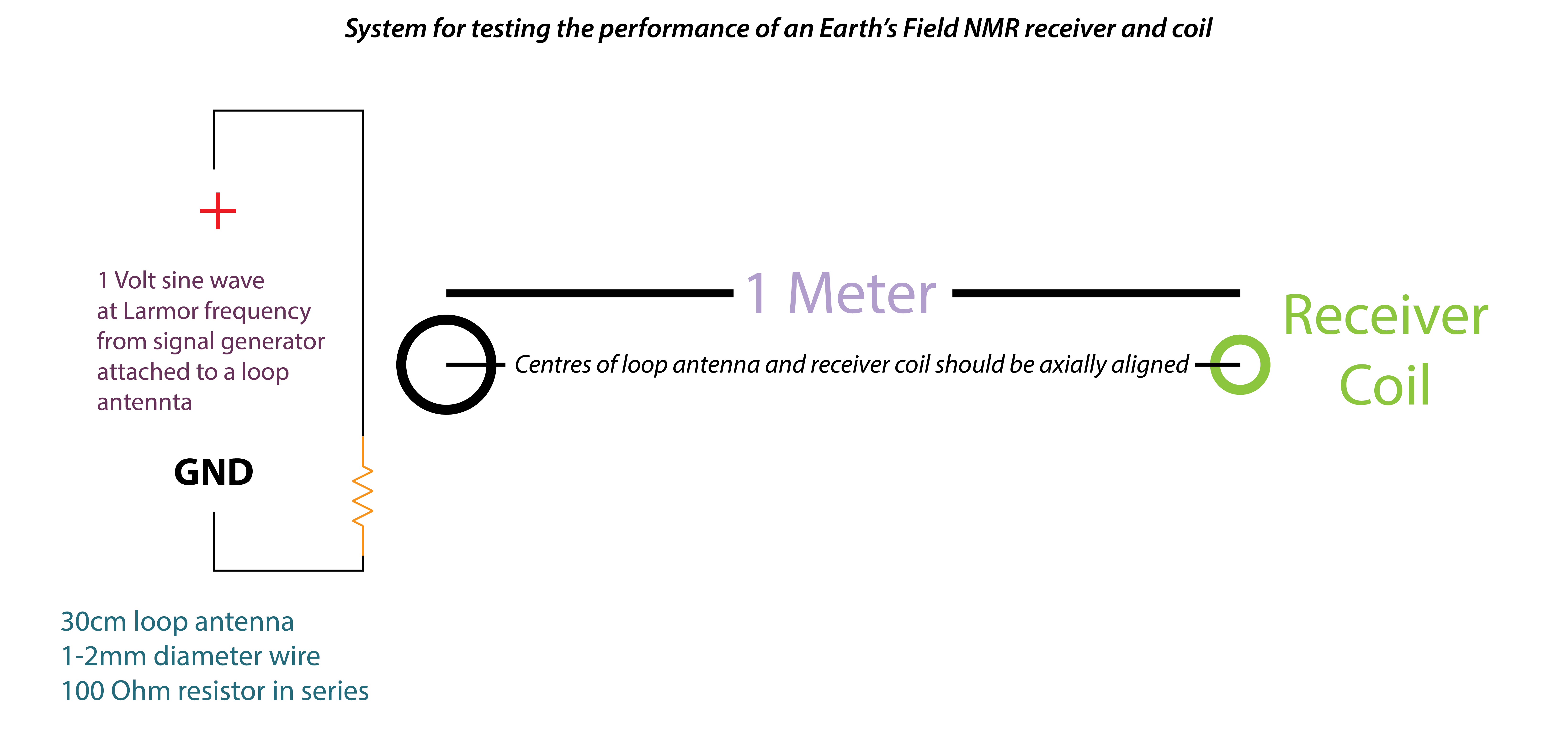
In the same way as before, we will test the coil's reception, but instead of using a smartphone's speaker, we'll utilize a loop antenna attached to a signal generator.
If you're using a real signal generator, set the output to a 1Vpp sine wave. To use a smartphone signal generator, an oscilloscope is required to measure the output of the audio jack and determine the correct volume level for an output of 1 Volt peak-to-peak.
Solder a 100 Ohm resistor in series with a 30cm wire. Attach one end of the wire to the signal generator output and the other to the generator ground. If you're using a smartphone with a headphone jack, a modified 30cm mono audio cable with a 3.5mm jack could be utilized.
![]()
The loop antenna should be axially aligned with the centre of the receiver coil and placed 20cm away. Play a sine wave at a suitable value, such as 2kHz. The artificial signal should be quite noticeable on the spectrogram at 20cm. Gradually move the loop antenna further away, verifying that the signal remains visible.
To receive a decent signal at 1m, you might need to adjust various settings in the spectrogram software. In SDR#, fine-tuning settings such as zoom, contrast, range, offset, sample rate, and Fourier transform resolution can significantly enhance the sensitivity of the instrument.
Once a distance of 1m has been reached and the signal can still be detected, we can confirm that the system should be sufficient to receive an EFNMR signal.
-
9Test the polarization coil
You will need:
1 x 3S 11.1V LiPo battery
One or more
A charger capable of 3S charging
To charge the battery
*Warning* Under normal experimental conditions, the polarization coil is unlikely to overheat. However, if the battery switch is accidentally left on, overheating could occur. Always monitor the temperature of the coil, and ensure that it does not exceed 40°C. The maximum polarization time should be around 15 seconds, with intervals between polarization cycles. Using a smaller capacity battery decreases the risk of overheating, while using a 12V mains power source increases it. *Warning*
To initiate the polarizing mode in the coil, insert a battery into the socket and select the battery with the switch.
With a fully charged 11.1V LiPo battery, the coil produces a field of around 10mT (milliTeslas). This can be precisely tested using a device such as a WT10A magnetometer with an axial probe. For a general function check, you can use the compass in a smartphone. Hold the phone about 20cm away from the coil and use a compass or magnetometer app to observe the field change.
-
10Set up the experiment
Set up the tripod in an appropriate location, any sources of magnetism should be a minimum of 1 meter away, further if possible.
Always try to be as far as possible from sources of mains 50/60 Hz power.
If indoors, try to use the centre of the room and move furniture containing nails, springs etc to the sides of the room.
In places with high electrical interference, the direction of the coil is very important. Noise will often be high over an angle of 340 degrees or so and much lower over 20 degrees or so.
The theoretical optimal direction for the coil is exactly perpendicular to the direction of the main field, but in practice the best signal might be obtained at close to magnetic north, due to local interference.
Use your spectrogram software to study the noise in your location, rotate the coil 360 degrees and watch the effects on the waterfall display in particular.
Consider using the loop antenna test to help establish whether the location is suitable.
Nuclear Magnetic Resonance for Everyone
Explore the magnetic properties of hydrogen with this build guide


Discussions
Become a Hackaday.io Member
Create an account to leave a comment. Already have an account? Log In.