-
1Display Module - PCB Removal from Bezel
The display module requires the following modifications to improve performance in this project:
- Remove the protective film left on the LED display on the PCB.
- Bypass the reverse power protection and on-board LDO.
- Cut the grounding link for the negative input terminal of the ADC - under the display.
The ADC has fully differential inputs, but the negative input is linked to ground by default.
To carry out the modifications, first remove the PCB from the bezel.
-
2Display Module - Protective Film Removal
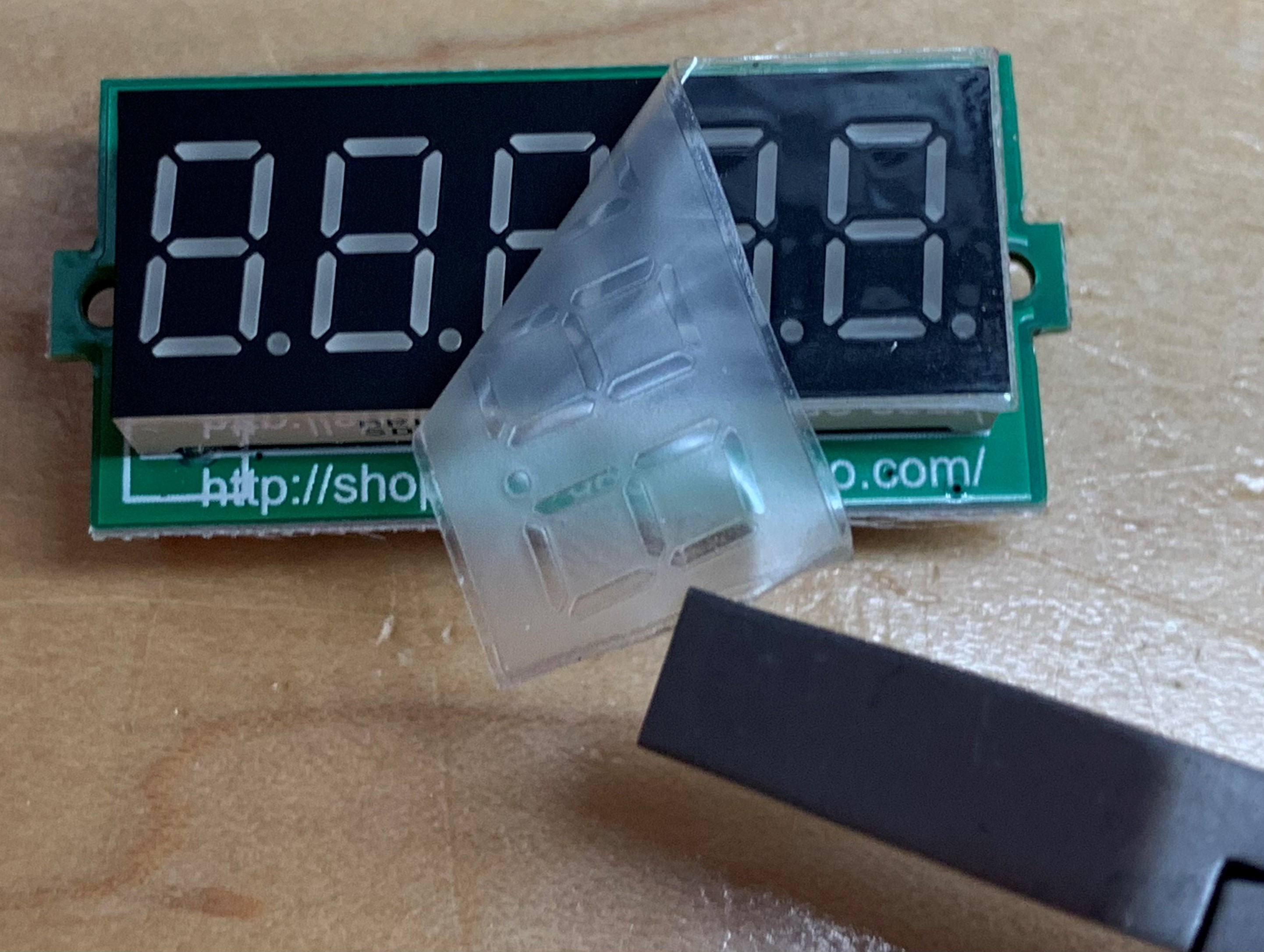
The display modules are assembled with the protective film left on the LED display. That film should be obviously removed, improving the display clarity.
![]()
-
3Display Module - Voltage Regulator Bypass
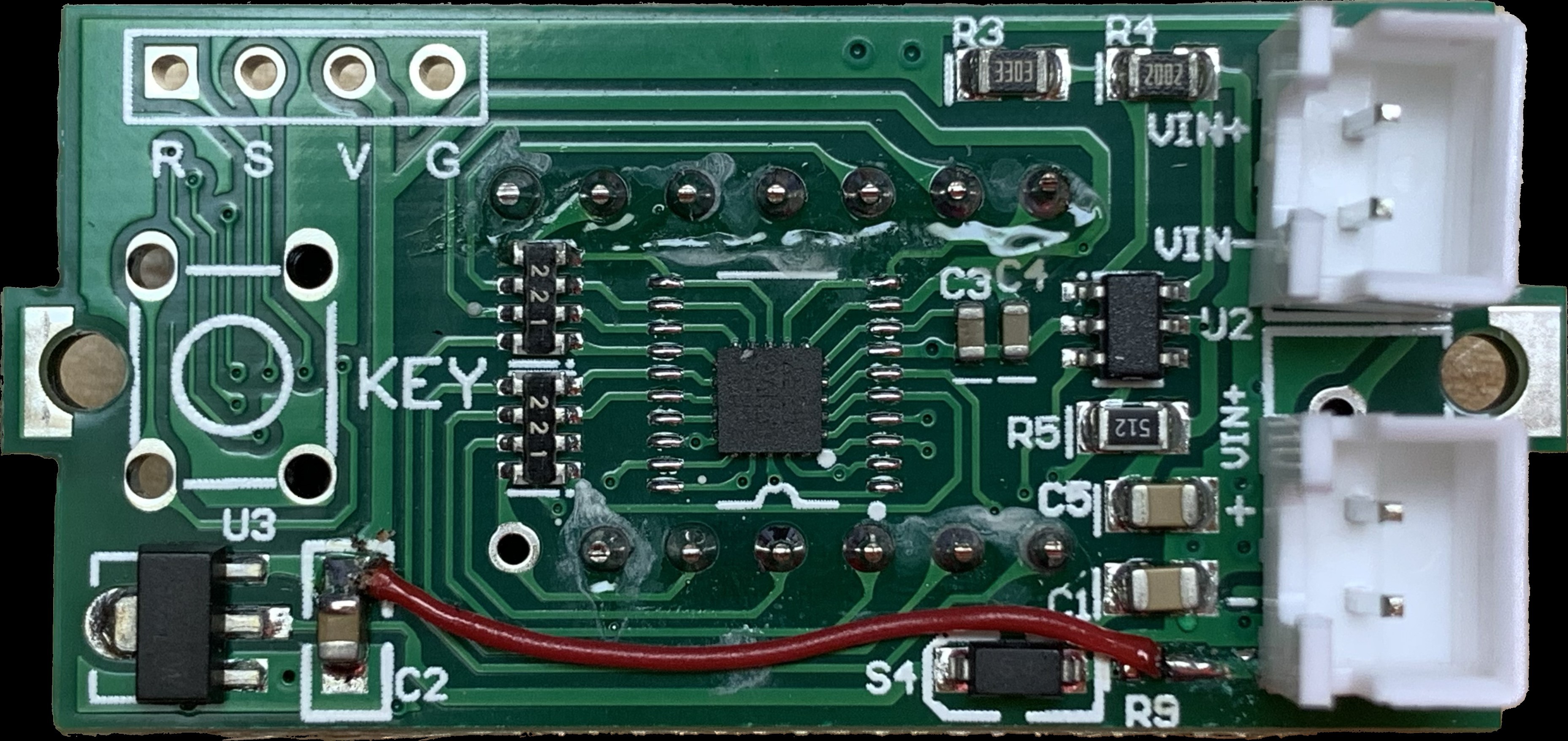
Solder a piece of wire between the right side of R9 and the upper side of C2. This bypasses the series resistor R9, the Schottky diode S4, and the 3.3V voltage regulator U3.
The STM8 MCU U4 and the ADC U2 can operate over the entire supply range of the milliohm meter (3V to 5V) without additional regulation. This modification ensures satisfactory performance of the display all the way to full battery discharge at 3.0V.
![]()
-
4Display Module - Desolder the LED Display
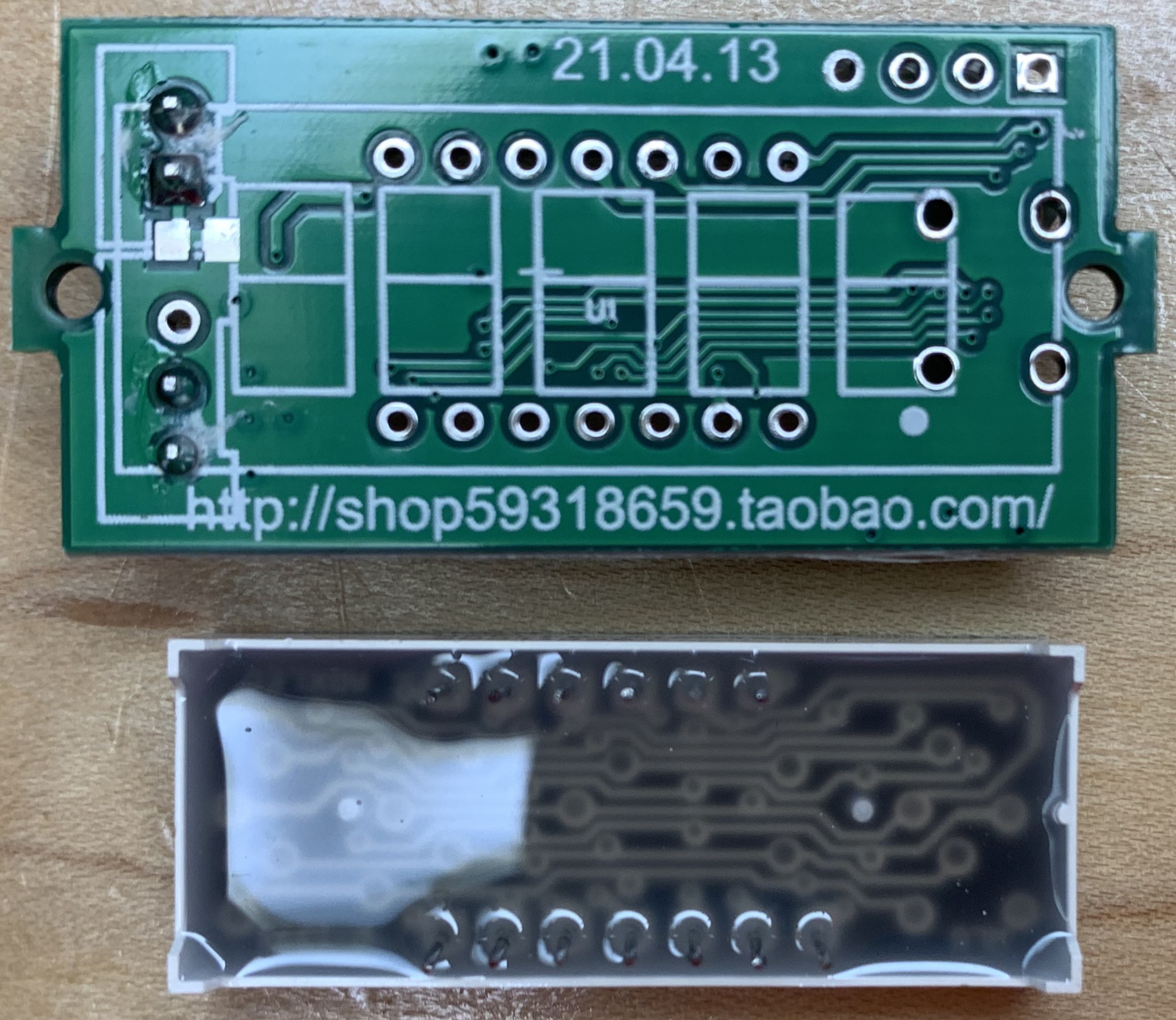
The steps that follow require access to the front side of the PCB. Thus, the LED display has to be desoldered.
![]()
-
5Display Module - Remove the VIN- grounding link
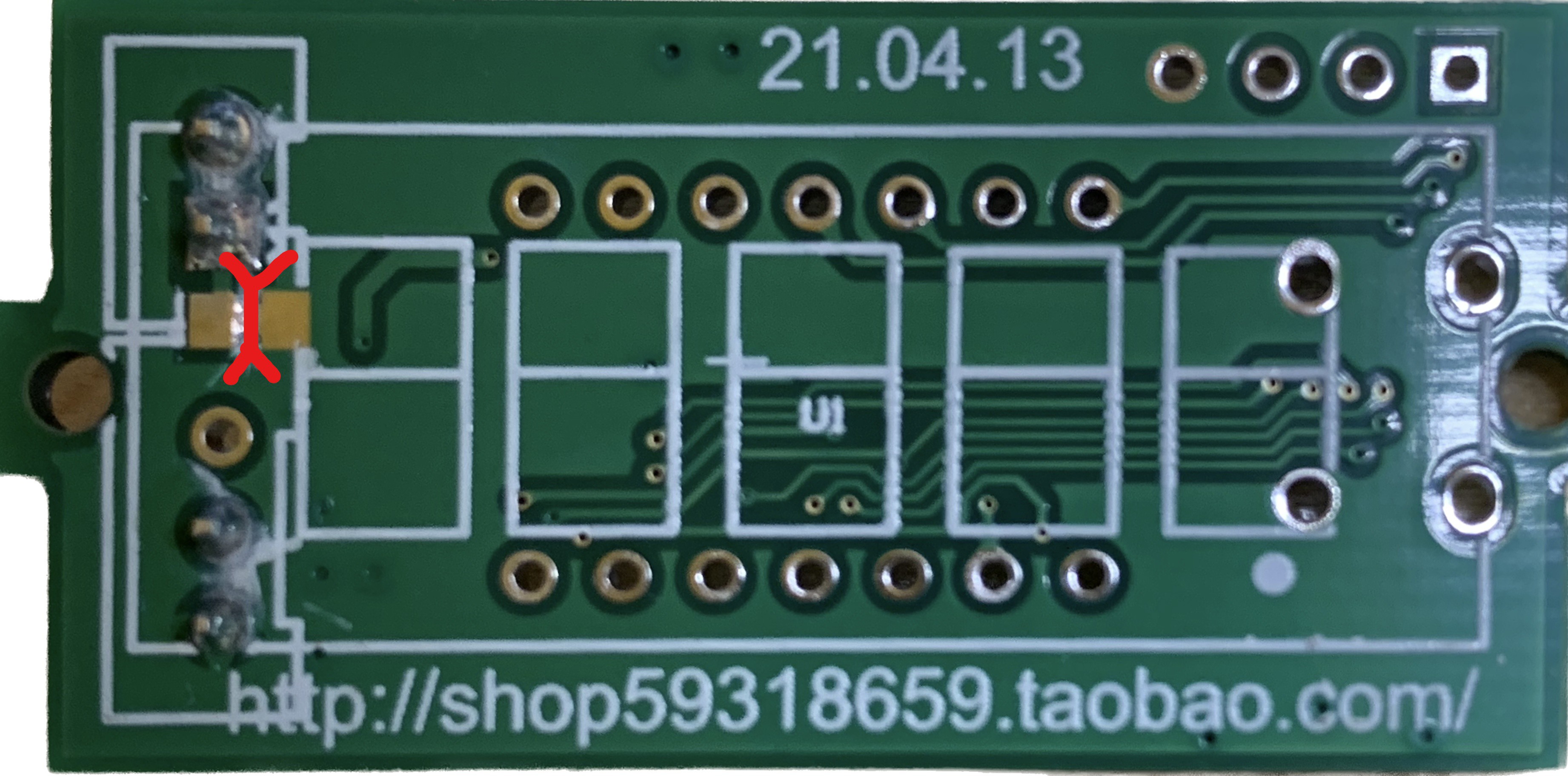
The grounding link shall be cut as shown below.
This link has to be cut to leverage the full accuracy of the ADC.
![]()
-
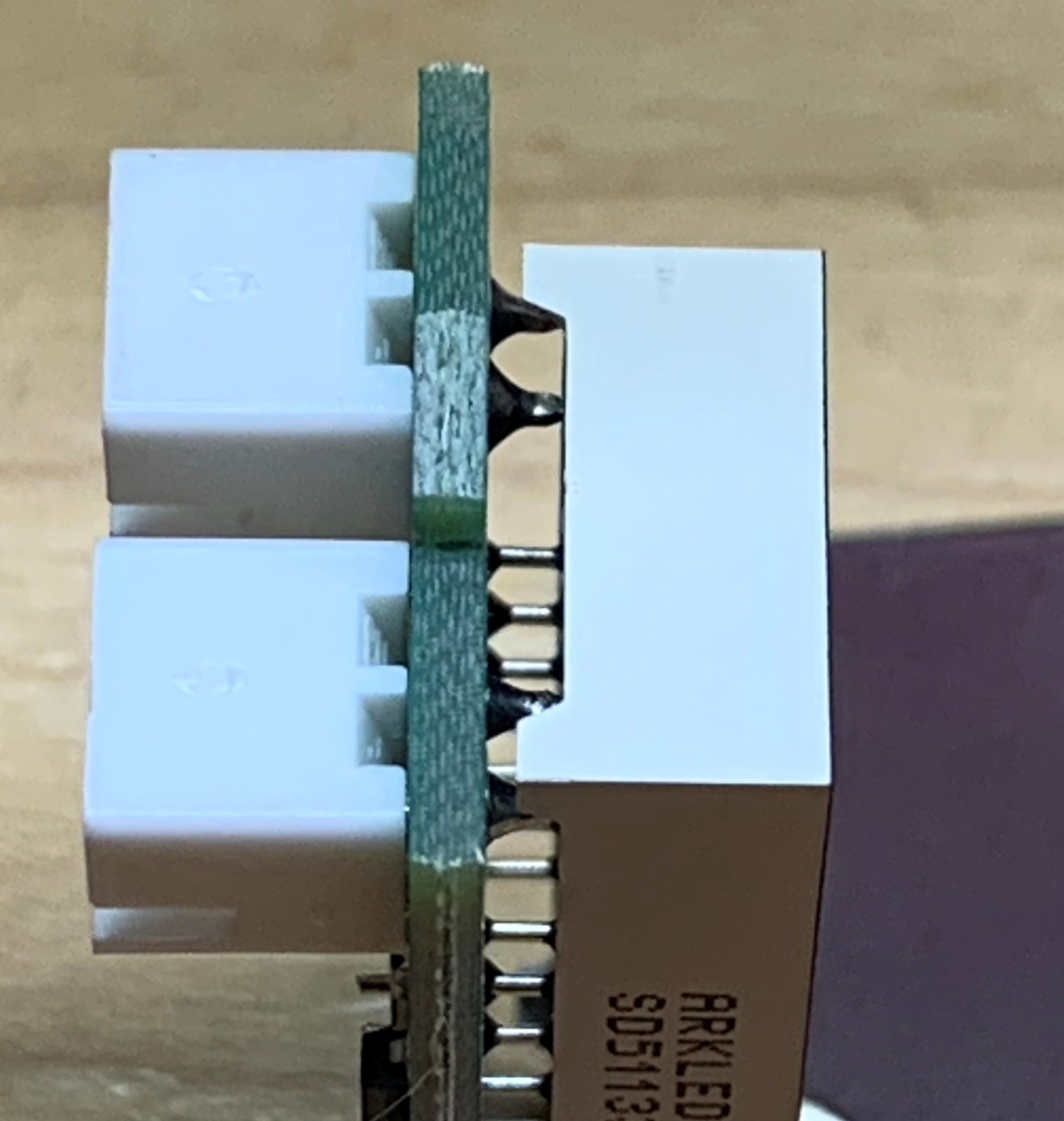
6Display Module - Reinstall the LED Display
Observe the display orientation - the decimal points have to be on the bottom of the front face of the PCB, when oriented to read the silkscreen right-side up.
Also, the soldering of the display is best accomplished with the PCB and the display put back into the bezel. That way the display can be spaced properly from the PCB so that the bezel will be held tightly in place. Other option is to glue the bezel in place.
![]()
 Kuba Sunderland-Ober
Discussions
Become a Hackaday.io Member
Create an account to leave a comment. Already have an account? Log In.
Awesome project. I did build it just fine, worked on first power on. As for the temperature drift I build a 12 Ohm resistor from aprox. 22cm of 0.1mm manganine wire (wrapped around piece of leftover PCB) which seems to be stable enough, the output drifts less than 1mV when measuring 1Ohm resistor.
Update: I found thick managine wire around 1Ohm that itself does not drift much and the output drifts less than 0.4mV on full scale measurements, which is +4 on the last digit after a few seconds between the open state and the measuring state.
Are you sure? yes | no
Wow, I didn't expect anyone other than me to actually build this thing. There's a v2 coming that implements the ADC and display as well, using cheap parts, nothing programmable nor exotic. I'll gladly send the PCBs for that your way if you wish, since I can't really use more than one or two, and there's no point in getting less than 5 from PCBWay.
Are you sure? yes | no
That would be awesome however depending on where you live sending them may end up more expensive than ordering from PCBWay... (I live in Czech Republic).
Are you sure? yes | no