MaBe42
-
It works!
05/27/2023 at 15:53 • 0 commentsIt works right from the beginning. Testing after more or less each step paid off.
https://cdn.hackaday.io/files/1912688183210112/from_above.mp4
https://cdn.hackaday.io/files/1912688183210112/chaotic_lighthouse.mp4
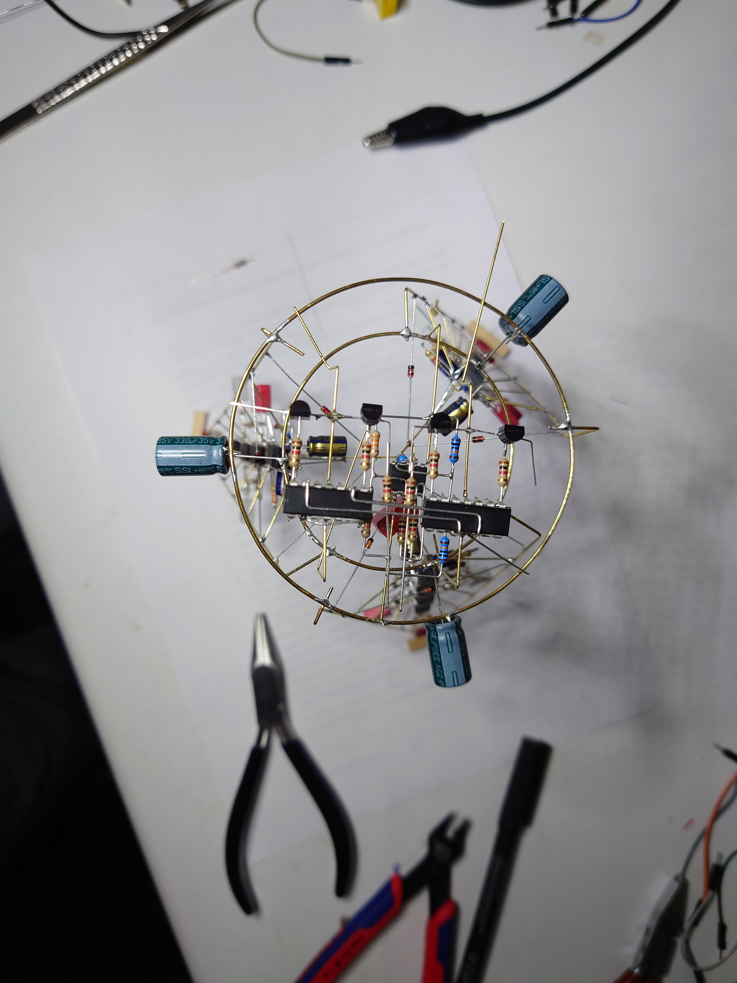
Many basic op amp circuits are used in this sculpture: integrators and differentiators in the chaotic circuits, buffers and amplifiers in the signal conditioning, a very dirty triangle signal generator, a peak detector, building the difference between signals and converting analog to PWM. Best practices were not always applied. But in this project it's not about signal quality in the first place. The idea was to use the op amps to make the lighthouse blink in a non-repetitive way. This would also be possible with a micro controller and a few lines of code - but much less fun!
-
Putting the parts together
05/27/2023 at 15:43 • 0 commentsThis was again a job where two hands are not enough, I chose to build a structure out of 10 diodes (1N4004 are more stable than 1N4148) to form the interface between the round base and the pentagonal tower.
I mounted the diodes with glue tack on a circle on paper, soldered the tower to them and then put it onto the base.
![]()
-
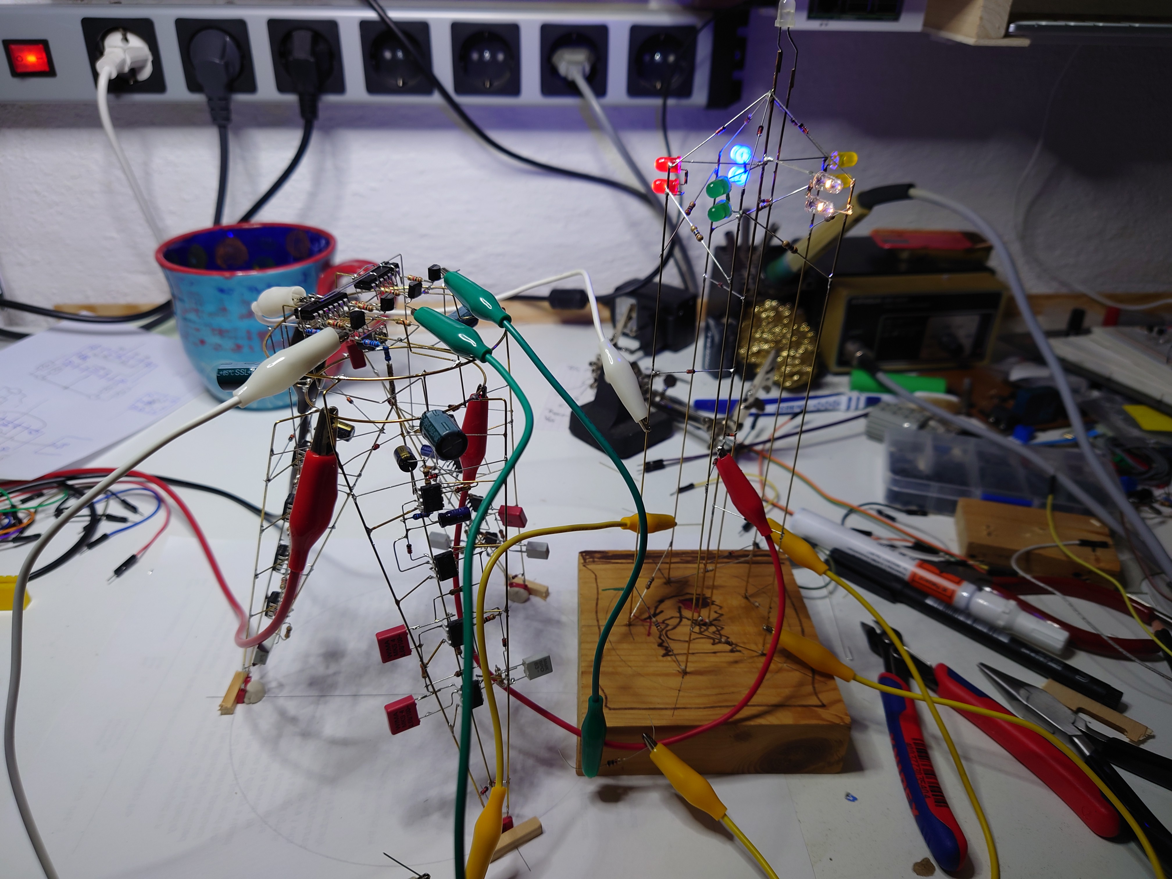
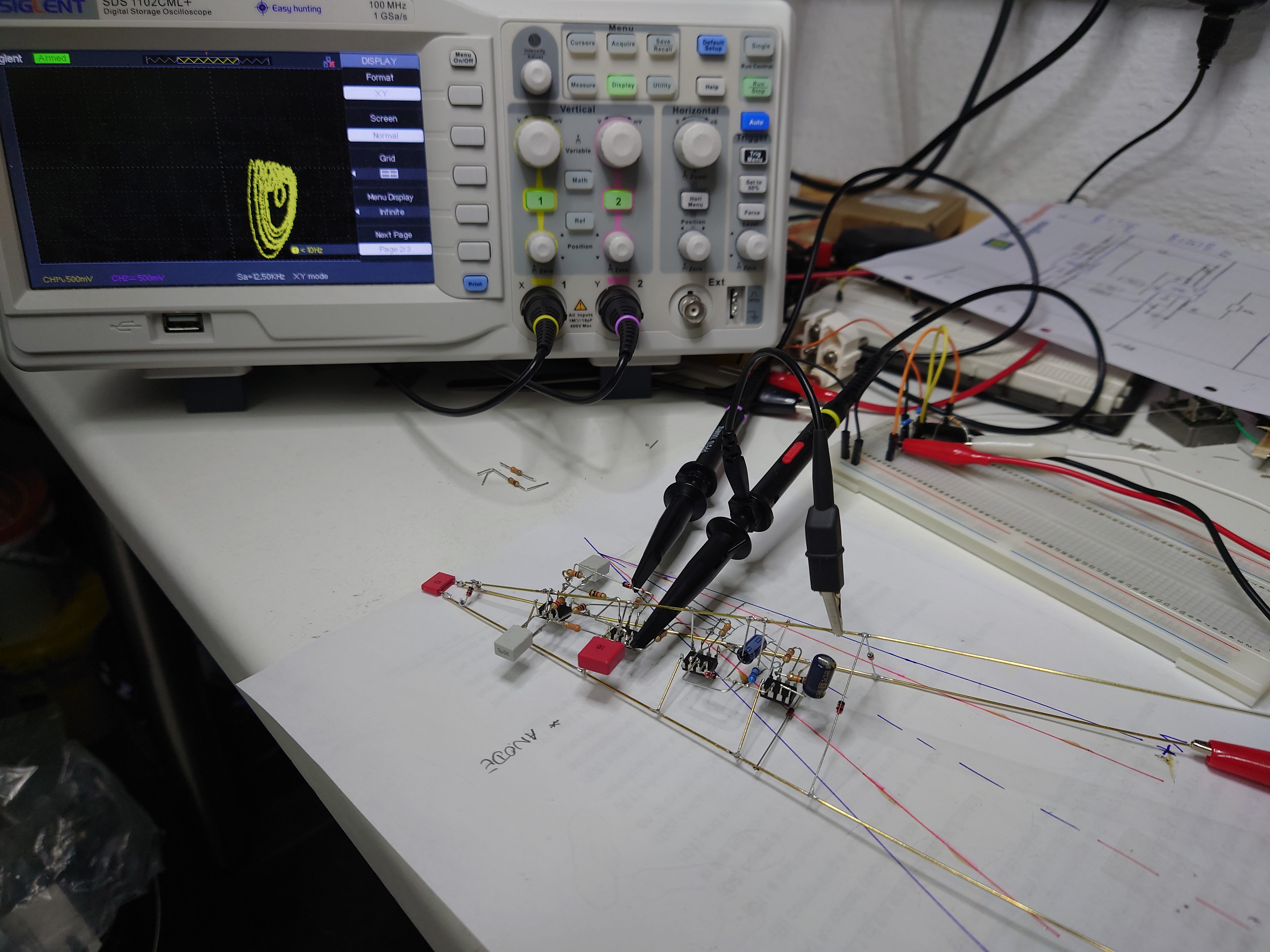
Testing
05/27/2023 at 15:38 • 0 commentsWith so many solder joints, I decided to test the functionality quite often during the build. It was sometimes quite messy.
![]()
-
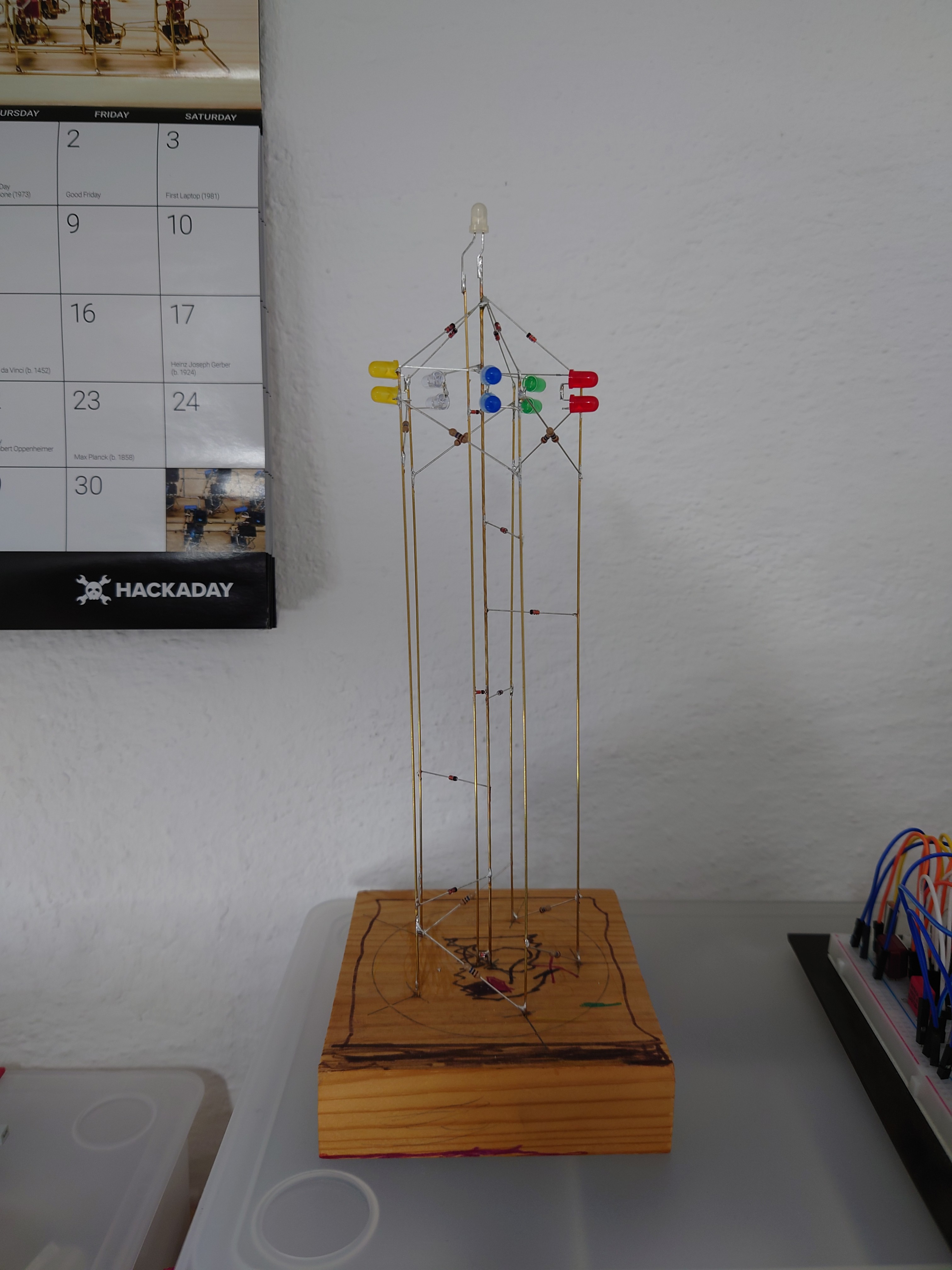
The upper tower
05/27/2023 at 15:35 • 0 commentsThe upper tower is a rather simple structure with a pentagonal cross-section. All made from brass wire, V+ in the center, diodes building a roof-like structure and some 10M resistors and diodes (some are SMD) to provide mechanical stability.
![]()
-
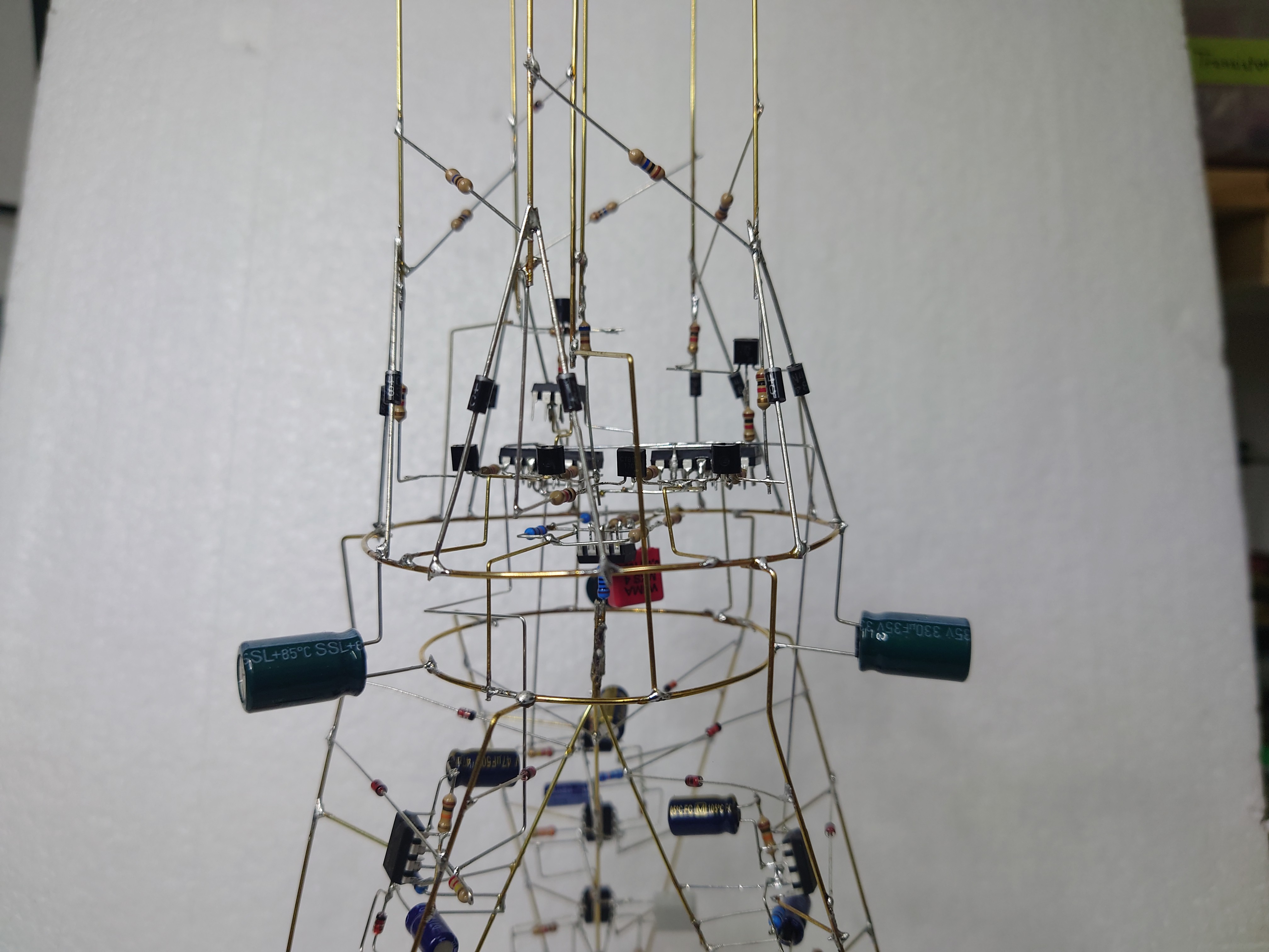
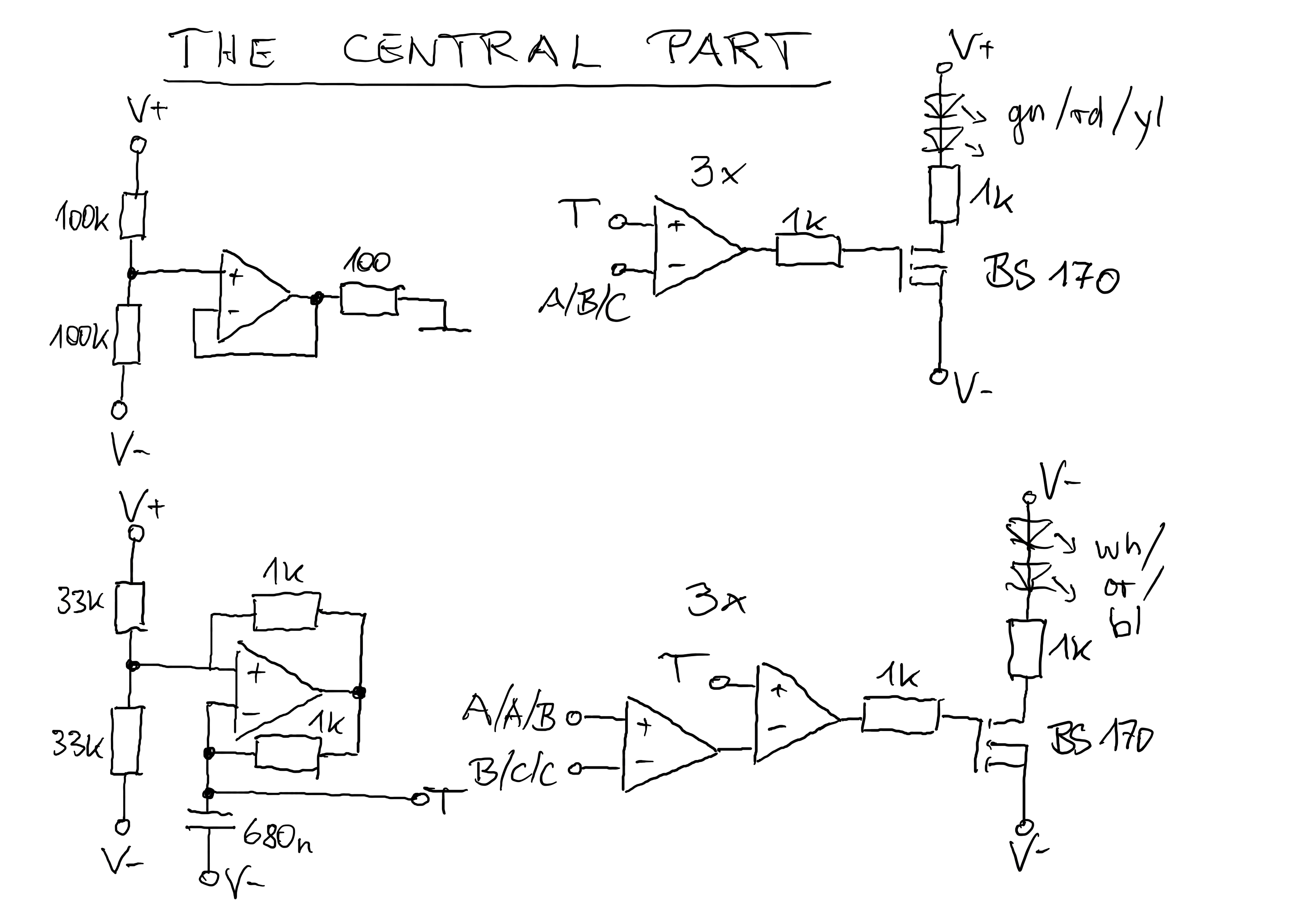
The central part
05/27/2023 at 14:36 • 0 commentsIn the central part, the virtual ground is generated and also a kind of a triangular signal (very quick and dirty) which is needed for the conversion of the analog signal to PWM for the LEDs. Finally, the signals A, B and C from the legs are either directly used to drive the LEDs or differences are generated to have six different rhythms.
![]()
For the orange LED I took a 680R resistor instead the 1k to have it a bit brighter.
The FETs are not really necessary since the LEDs consume only about 5mA. But when I designed everything I was not yet sure how many LEDs I would need to drive.
![]()
The large caps look cool and are needed to reduce some 50Hz ripple I had observed on some of the signals.
-
Building the legs
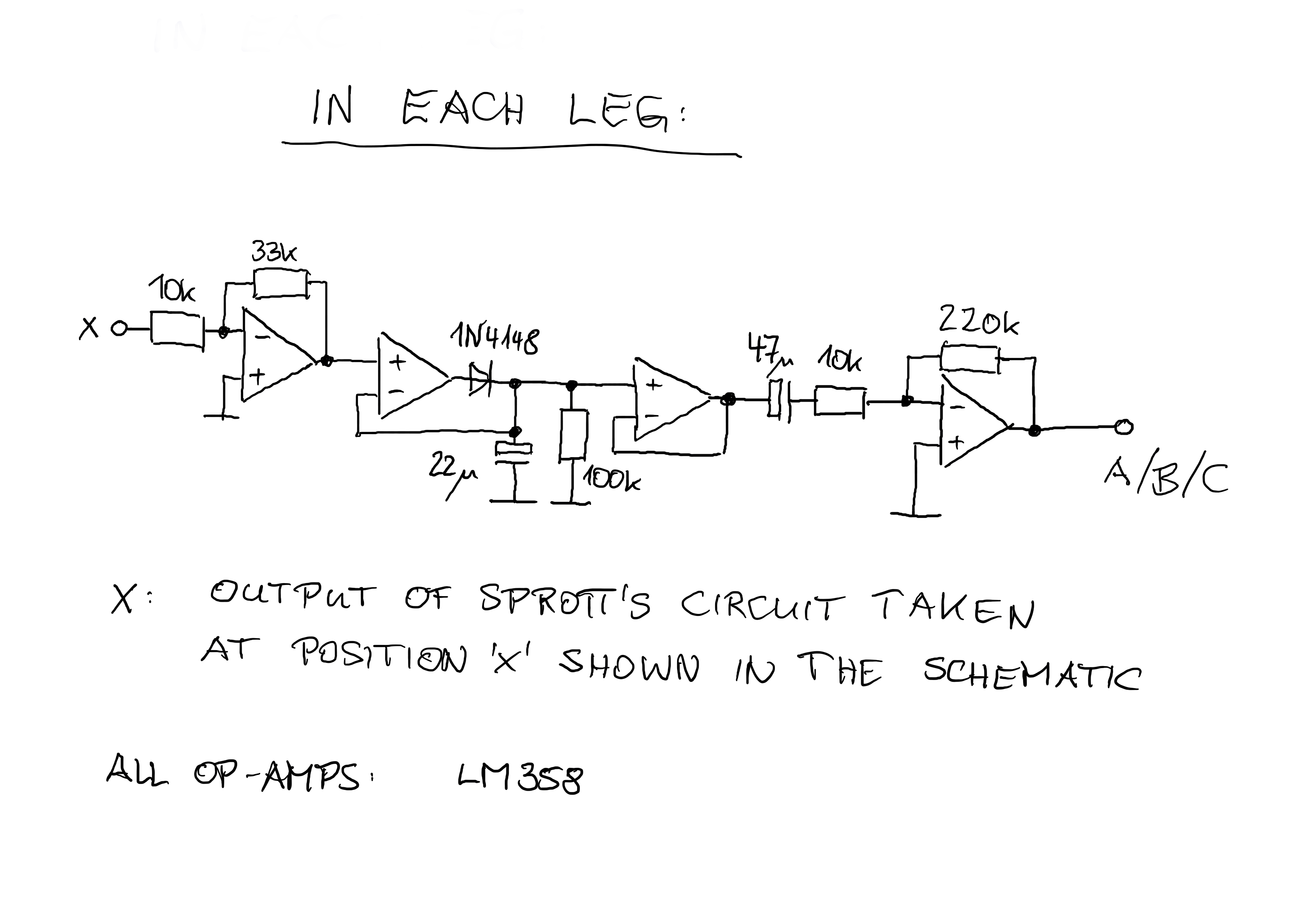
05/27/2023 at 08:07 • 0 commentsIn each leg there is one of Sprott's chaotic circuit, a peak detector and some signal conditioning:
![]()
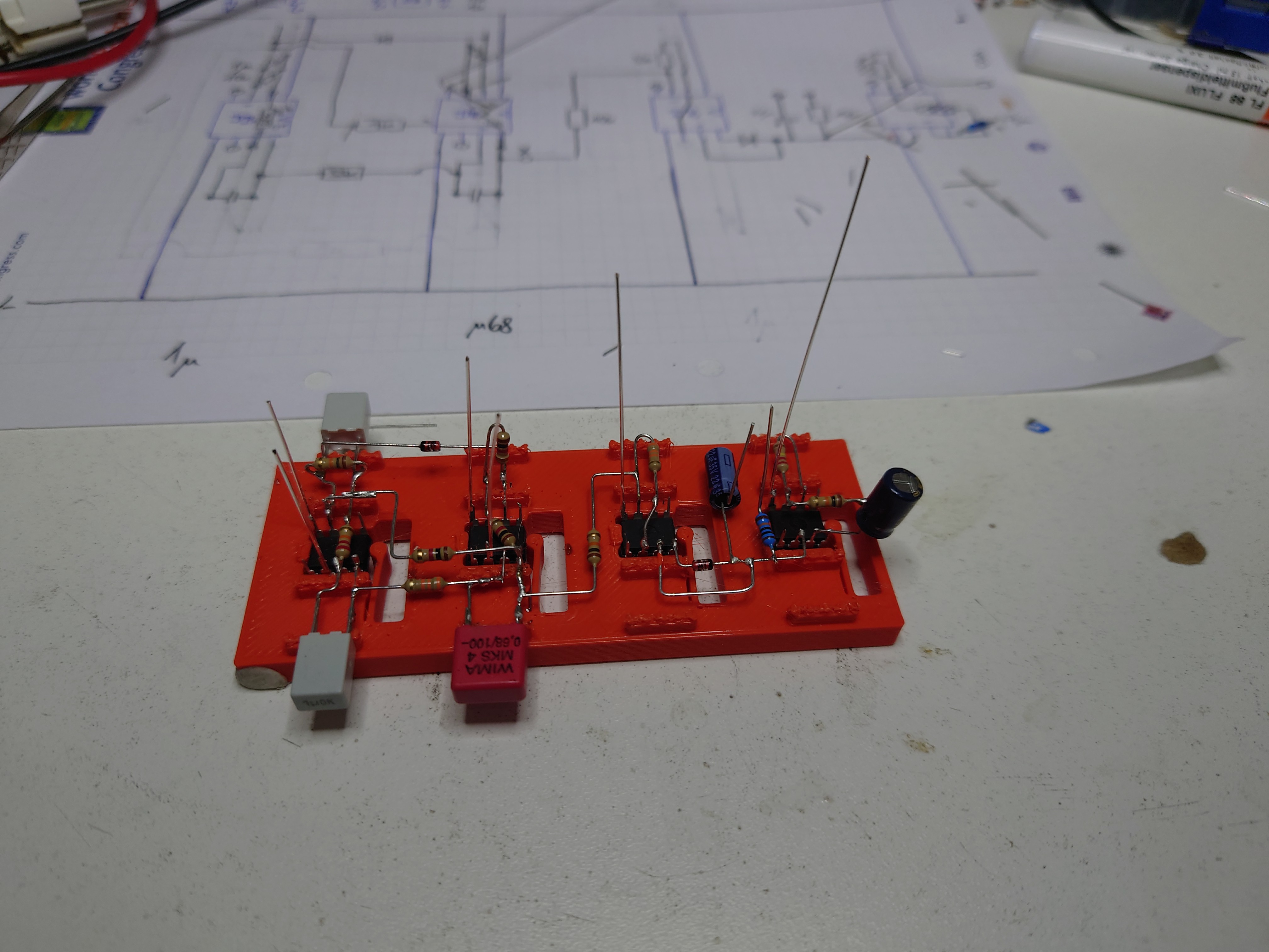
To facilitate soldering I had designed a little jig and 3d printed which helped a lot getting the job done:
![]()
In the background, a plan can be seen where I had "translated" the schematic into a design for soldering.
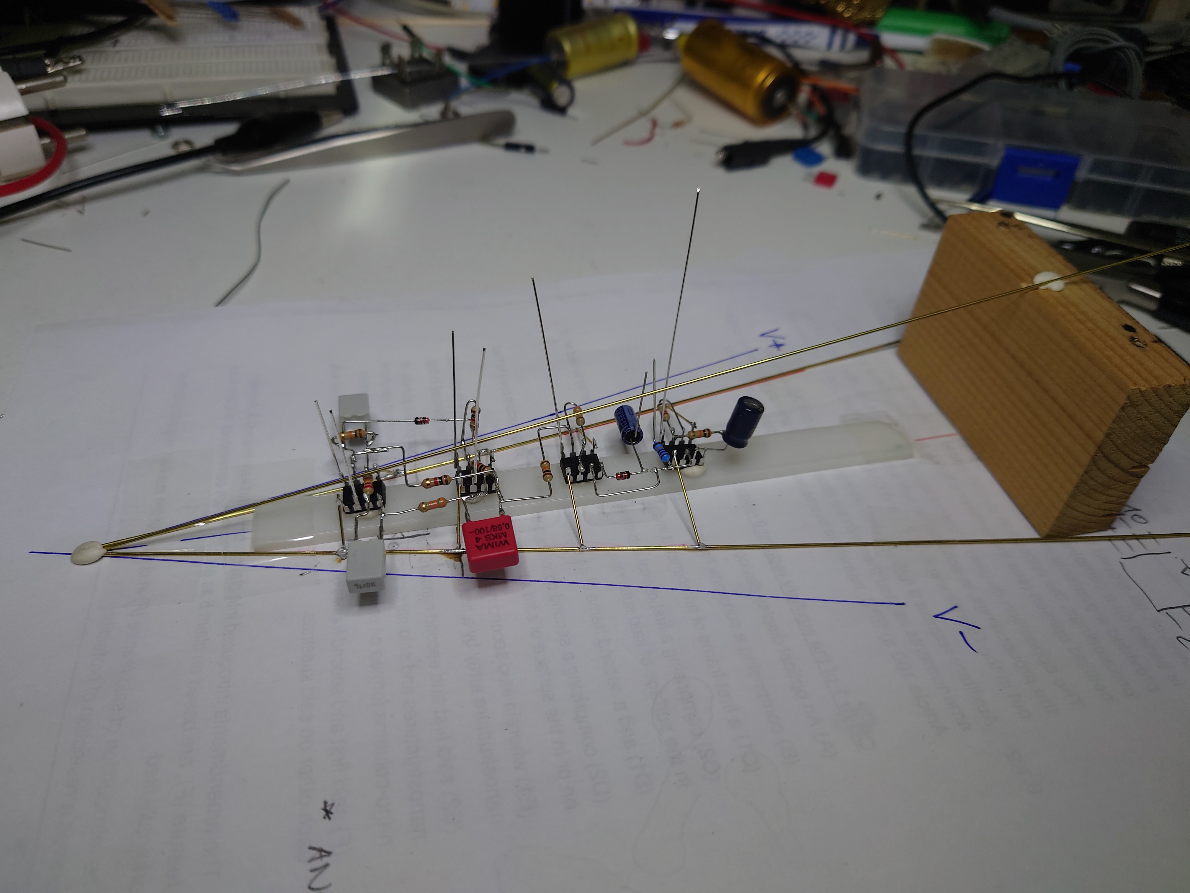
For assembling the triangular leg (each brass wire is a supply (V+, V- and virtual ground) I had another jig. This time more "ad hoc" using my favourite tool: glue tack.
![]()
After building of each leg: testing!
![]()
As you can see, I added some 1N4148s for rigidity and a small cap as protective/isolating foot.
Putting the three legs together made me wish I was an octopus. But again a little jig and some glue tack helped a lot.
-
The chaotic circuit
05/26/2023 at 20:49 • 0 commentsThe circuit is Sprott's chaotic jerk circuit.
![]()
The schematic is linked from the above website. I use the signal 'x' for my lighthouse.
Let's label the resistor from top to bottom and then to the right. So the topmost is R1 and the rightmost is R6.
Caps labelled from left to right.
In my circuit all op amps are 1/2 of LM358 driven from a single 12V supply (which requires generating a virtual ground).
D = 1N4148
R1 = R2 = R3 = 1k
C1 = 1u
R4 = 10k
are always the same.
My three legs have all different combinations of the other components:
C2 = 1u / 680n / 680n
C3 = 680n / 1u / 680n
R5 = 22k / 33k / 22k
R6 = 33k / 22k / 33k -
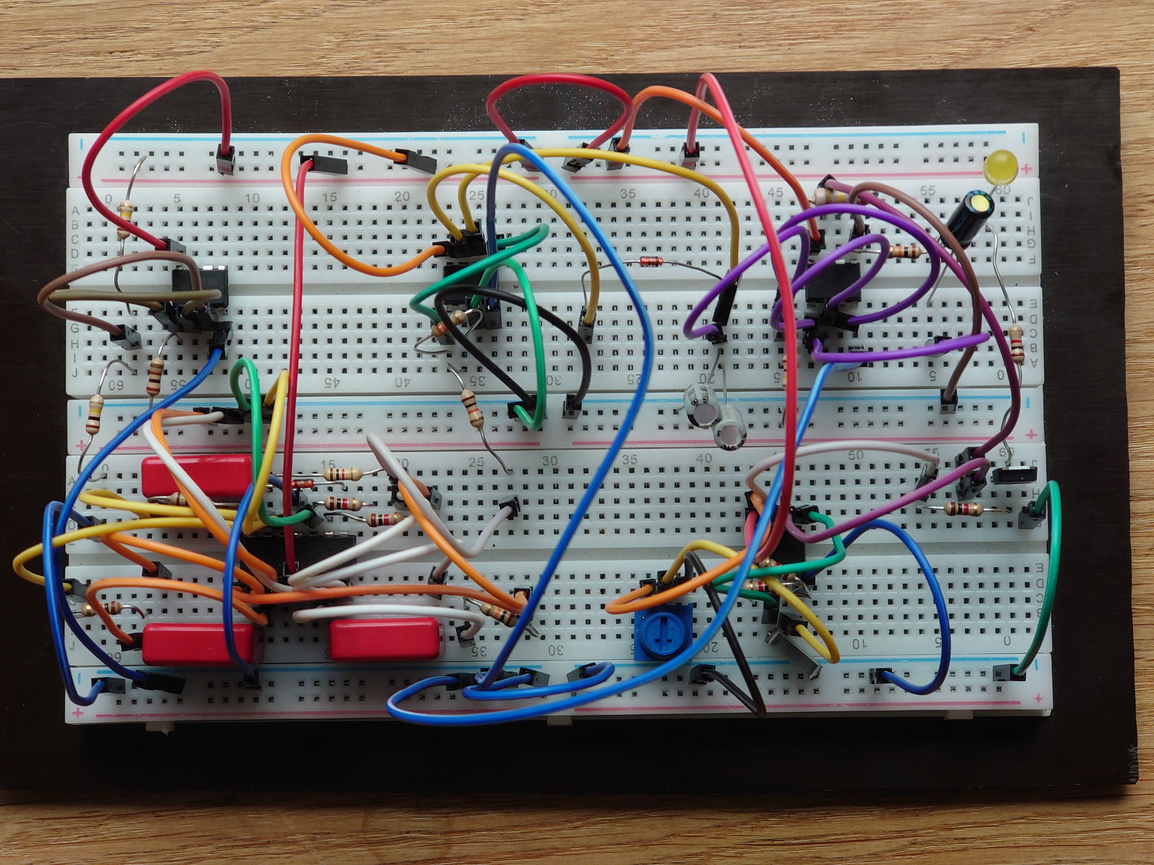
First build on a breadboard
05/26/2023 at 20:39 • 0 commentsI build the circuit on a breadboard to play around with the resistors and caps which influence the blinking of the LED. Looks quite chaotic. But there is a system in the colours of the wires.
![]()
There is also a video showing this circuit in operation.
Chaotic Lighthouse
A circuit sculpture to participate in the 2023 op amp challenge.