-
Boards have arrived!
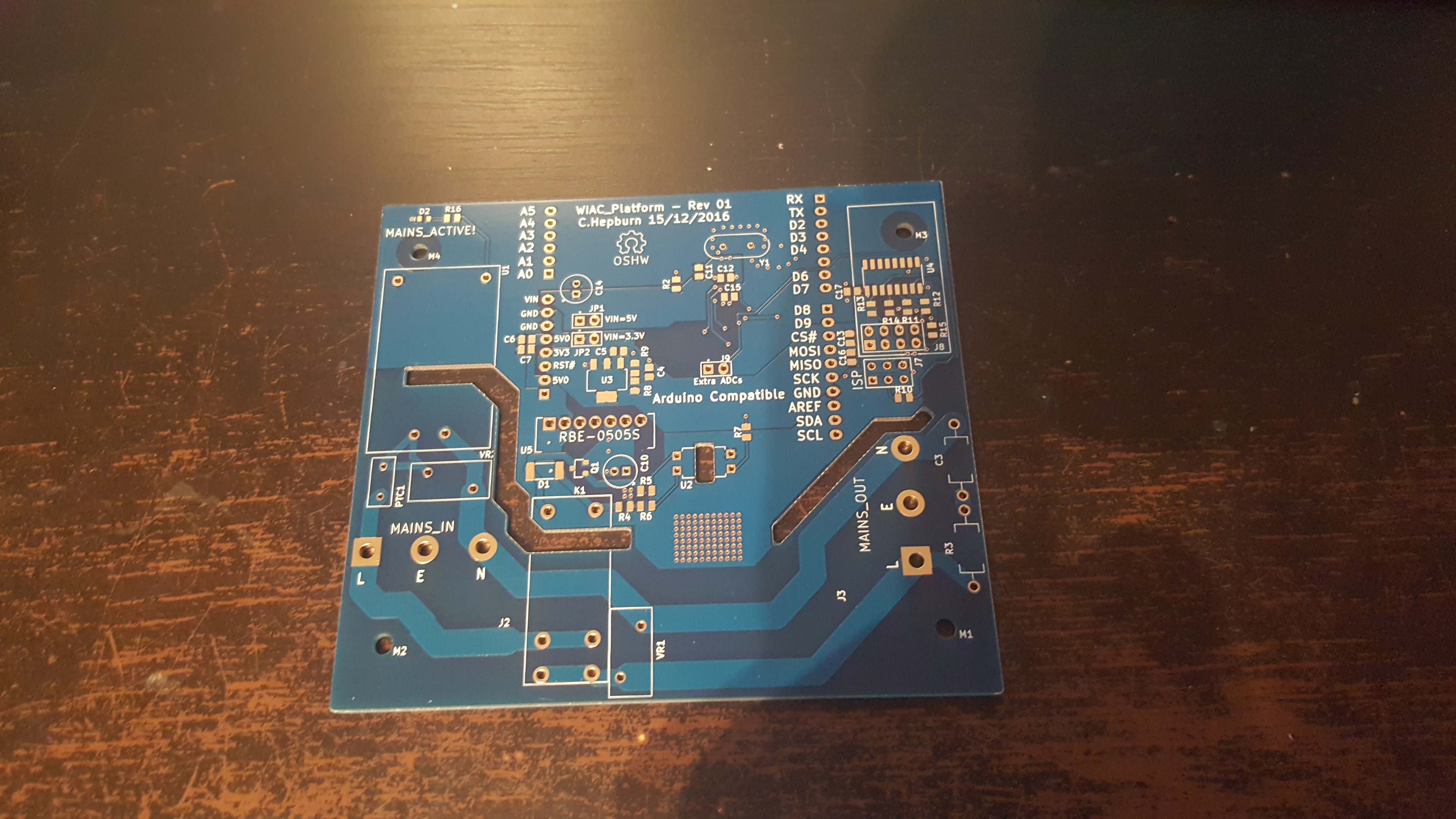
12/29/2016 at 12:23 • 0 commentsI sent the gerbers off to China as the UK board fabs were really expensive for a 10x10cm board (about £35-50 per unit!) and only could do 7 day turnaround at a sensible cost. I went with a fab called Smarter-Prototyping (NOA Labs) and they turned out quite nicely! I was able to get 10 boards with ENIG finish and blue solder mask on a 4 day turnaround for <£50 delivered with customs. The best part was, I sent the design out on the 15th December and had the boards in hand on the 23rd December before Christmas. Impressive turnaround overall. Some shots of one fo the boards are below.
![]()
![]()
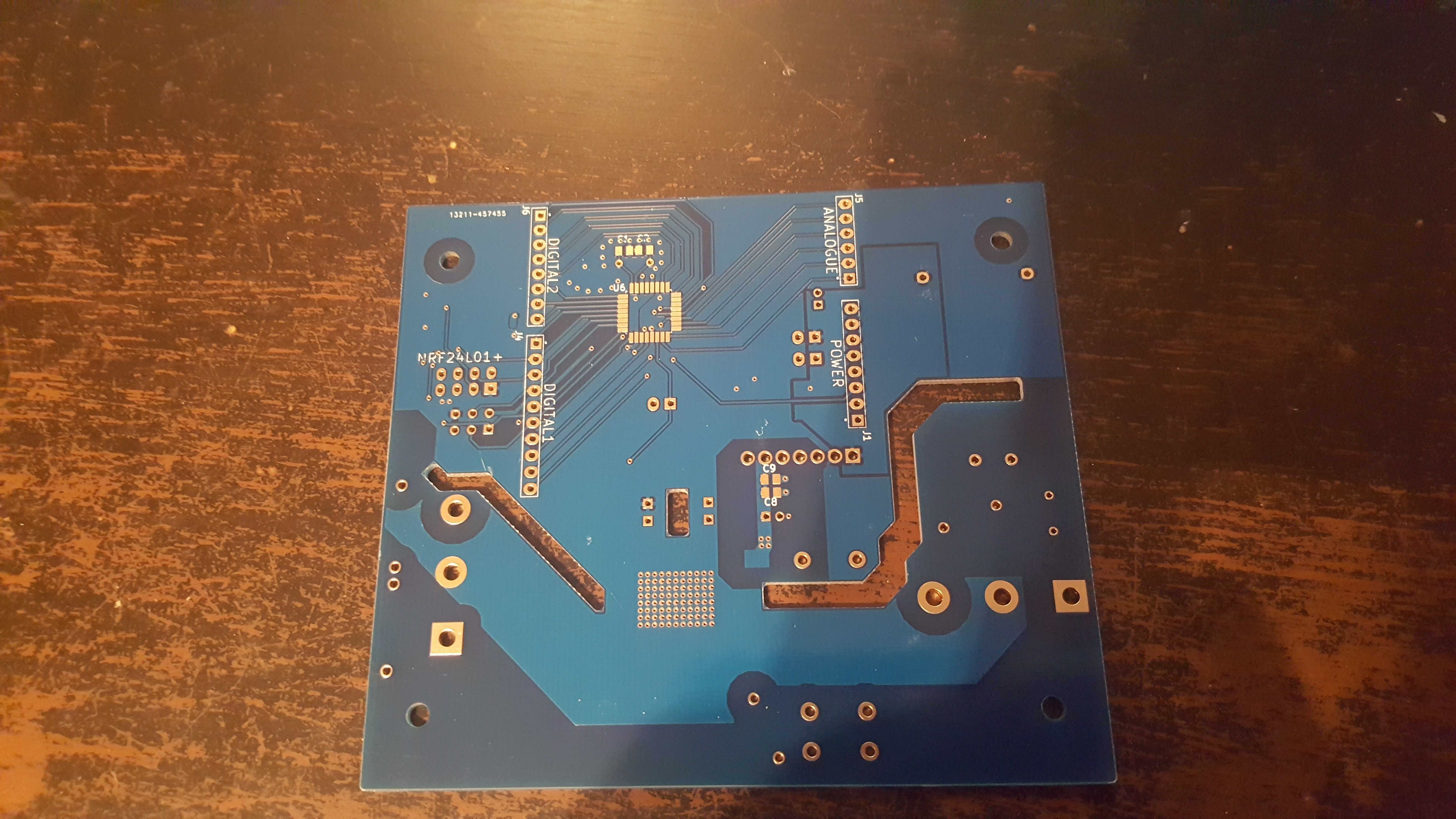
Whilst reviewing these boards I noticed a reasonably critical mistake in the isolation section. In my rush to get these boards out before Christmas it seems I got a bit excited and forgot to remove the planes around the relay pin area and the optoislolator , effectively only obeying clearance on the isolated DCDC output nets but none of the other nets. In the second revision I'll probably force every net on the isolated side to have a specific type of netclass and then ensure the clearance and trim the planes further back..
The worse part seems to be the 5V which runs right next to the relay coil pin, therefore if there was a failure there would be a coupling mechanism to 5V through this pathway here. Still a lot to learn with isolated designs it seems :(. Therefore there is a potential safety issue of the relay coil does fail catastrophically. -
Formalising the Design - Layout Done
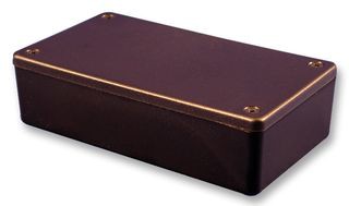
12/29/2016 at 12:02 • 0 commentsDoing the layout took a while as I had to make all the footprint libraries for this project and KiCAD had a bit of a learning curve with some of it's odd quirks! The layout was a bit tricky due to the clearances required and the low Z space I had inside my enclosure. I plan to fit everything inside of this enclosure:
http://uk.farnell.com/hammond/1591xxgsbk/enclosure-abs-black/dp/1877169
![]()
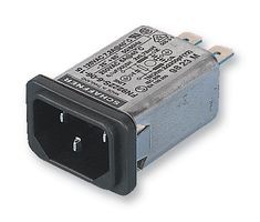
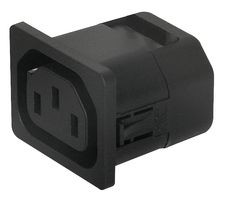
It is a tad expensive at £3.66 but should do the job nicely for a prototype. EMI filtering and connectivity was taken care by with:
http://uk.farnell.com/schaffner/fn9222sr-15-06/filter-15a-snap-in/dp/1190736
http://uk.farnell.com/schurter/6600-4120/outlet-iec-f-6600-10a/dp/2080452
![]()
![]()
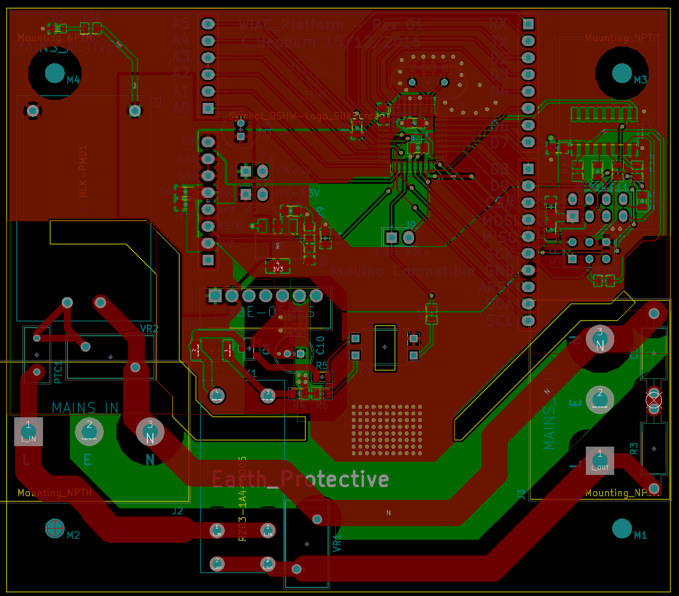
The rest of the connectors are standard 0.1" header type ones. Layout is shown below:
![]()
With this design it's very important that the live and neutral pins are mapped as shown in the layout to respect all the relevant clearances. Therefore this design is only suitable for keyed plug designs currently like we have in the UK. A reversable plug may not play nice with this revision.
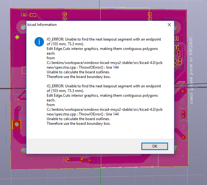
I also had this error come up as well, in case anyone else gets it, make sure to make sure there are no stray edge cut line objects hiding on top of another one. They won't be visible in the viewer but will give this error, so just find the culprit and delete it out.
![]()
-
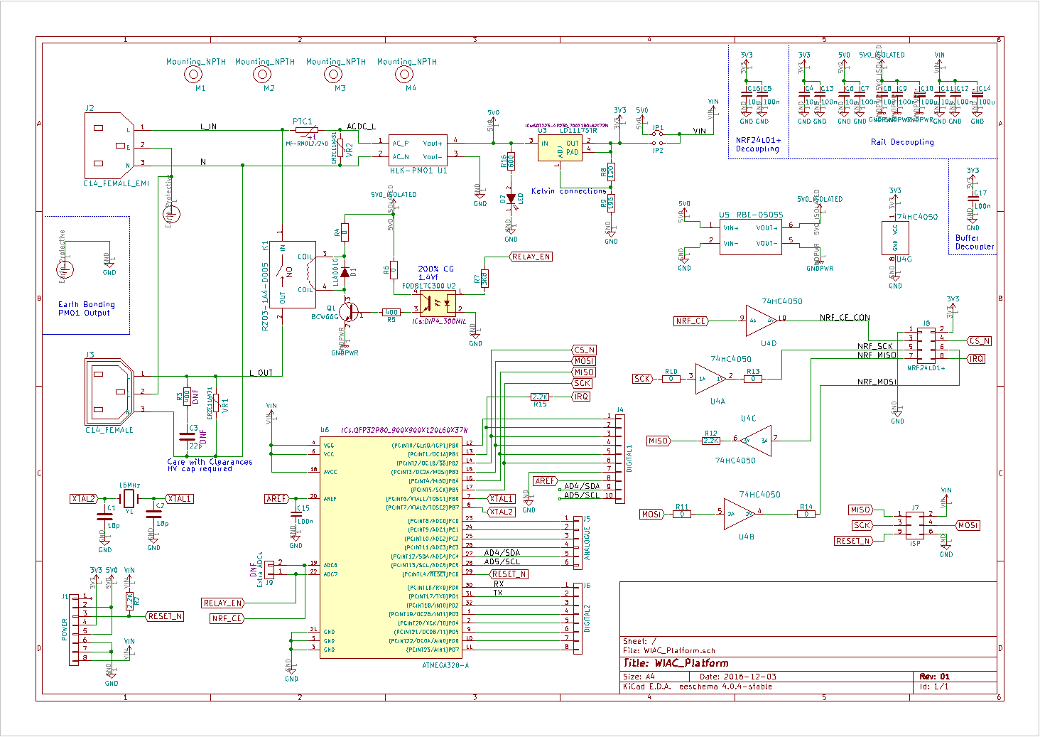
Formalising the Design - Schematic Done!
12/29/2016 at 11:29 • 0 commentsThe design has finally been captured in KiCAD. The design is effectively identical to the prototypes but I added in some extra features. There is a snubber for the relay output if the MOV has issues, I also added the ability to power the ATMega from 5V or 3.3V in order to avoid the need for level shifters in various projects.
I added a buffer to the NRF24L01+ in order to deal with the potential "shifting" which can now happen. This also increases longevity by not using the 5V tolerant inputs. A side effect of this is increased power rail range, so you can drive the module off of 3.3V too!
An isolated DCDC is used to drive the relay in case of relay failure coupling back to the MCU power rails which are accessable by the users.
![]()
-
Initial Prototype
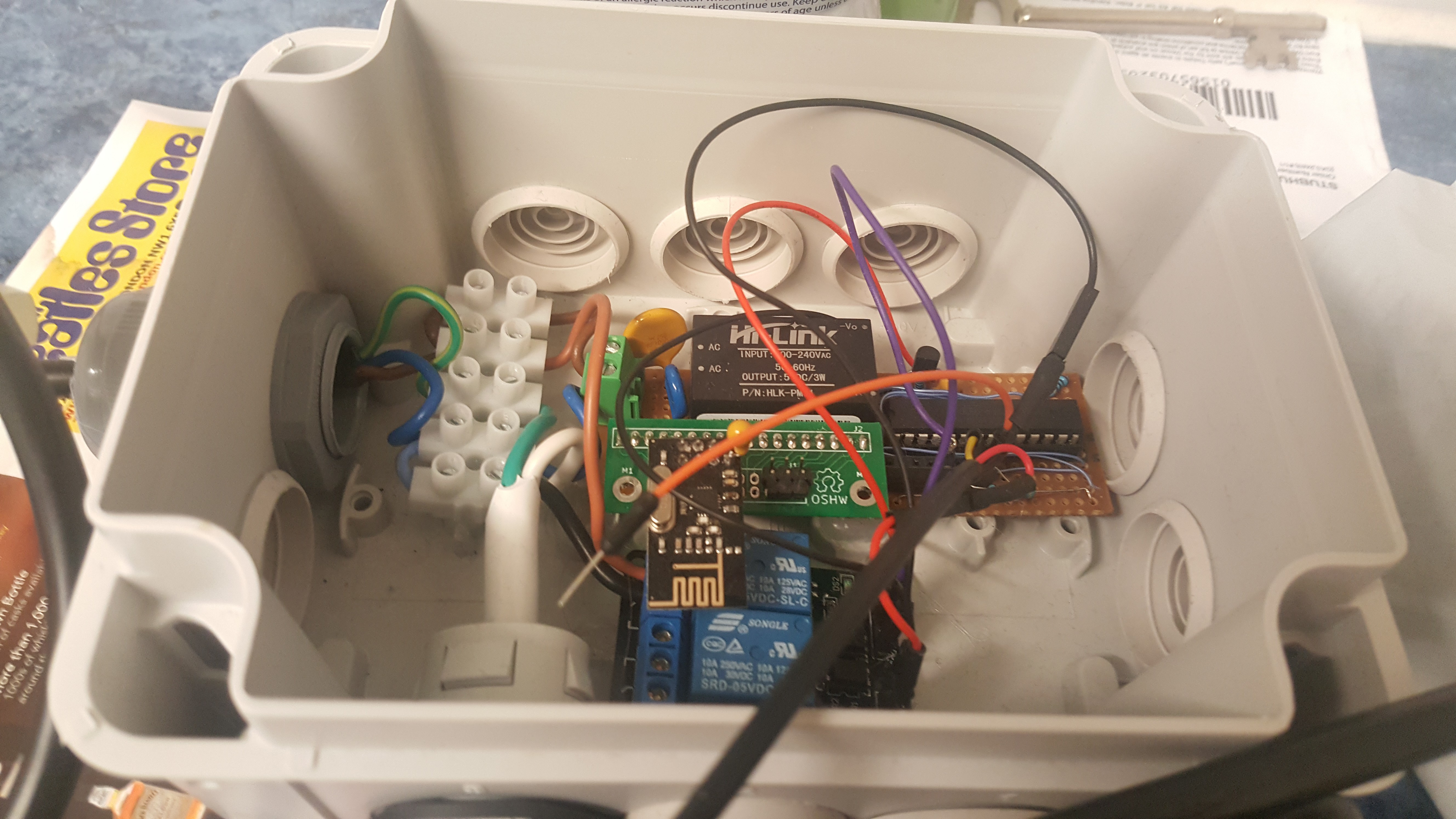
12/28/2016 at 18:24 • 0 commentsTo start off with I made a basic HW prototype. It was split into two parts, a transmitter and receiver although they are almost identical in terms of hardware. In order to improve the design of the iTead board I decided it would be good to use the mains to power the whole device. If you are doing a mains passthrough and have "unlimited" power, why not used that instead of having to have a micro USB or DC jack!
To do this I used the HLK-PM01 modules by hi-link. Although these modules are cheap chinese modules - they seem to have a small following for projects like these and are very cheap. A great review can be found [here](http://lygte-info.dk/review/Power Mains to 5V 0.6A Hi-Link HLK-PM01 UK.html) (not my review):During my basic test I was able to achieve basic functionality with the modules, however I had a lot of dropped packets.I believe this was due to the modules I bought off of ebay being "fakes". There are alternate ASICs which are "NRF24L01+" compatible but with inferior performance coming from China. They require a very stable power supply, I had to solder 10uF tantalums directly to the module to alleviate the packet dropping issue.
This is the main module to control the mains, I used the aforementioned HLK-PM01 and a cheap relay board from China to test out the initial functionality.
![]()
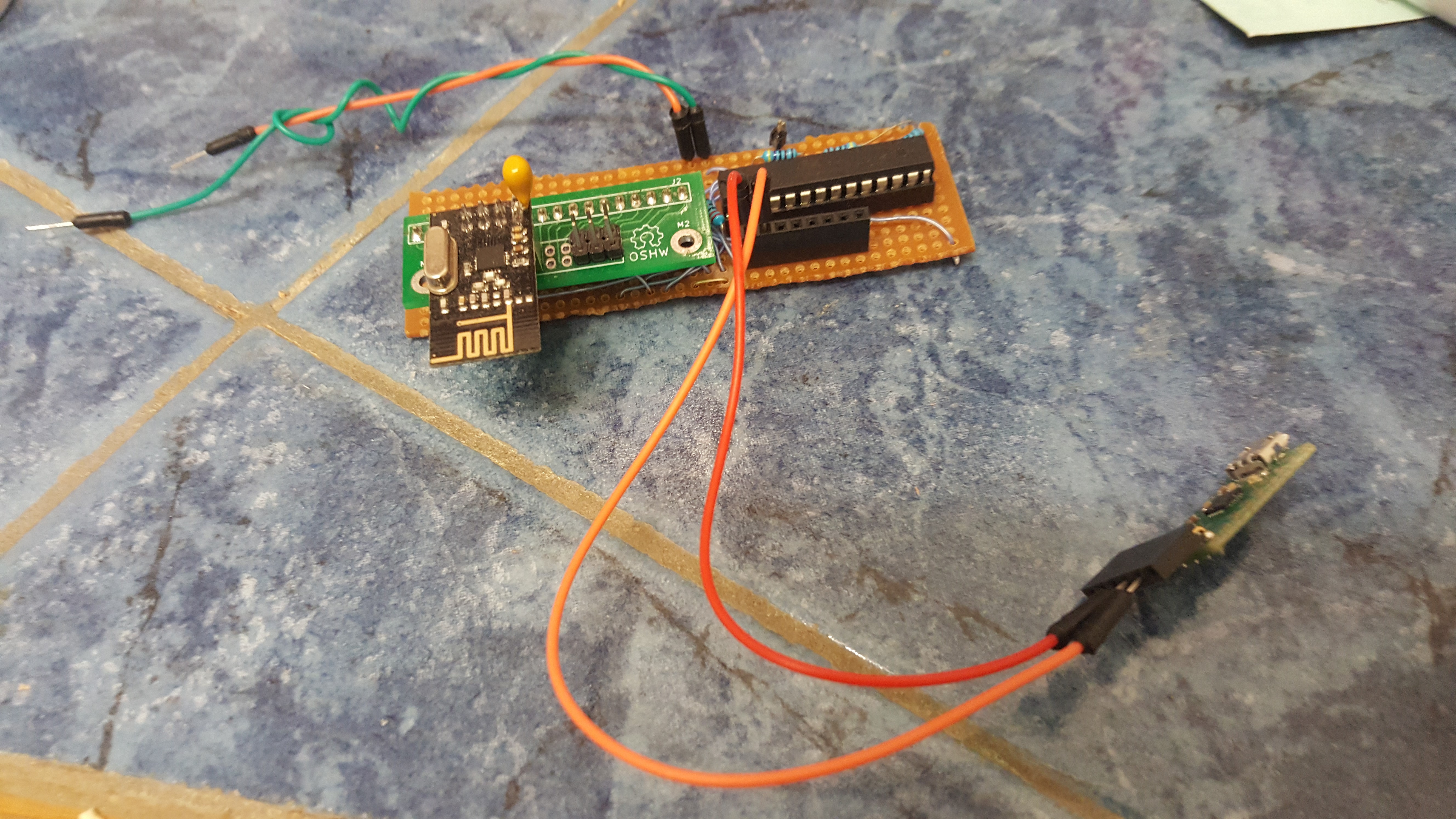
I made a similar board without the relay and ACDC module on it to act as a controller which can be used with my PC.![]()
-
Original Design Intent
12/28/2016 at 17:58 • 0 commentsIn order to make a flexible platform for users we need to think about the criteria needed for this project.
- Popular programmable microcontroller to be of use to a large community.
- Safety of user from high voltage nets running in the device.
- Small footprint so it can be integrated into more projects easily
- Easy to operate and program for beginners, no easy way to pose a danger to one’s self.
- Integrated wireless functionality of some sort for home automation use.
Looking at these criteria it seems that Arduino would be the best microcontroller of choice. There are plenty of libraries and shields out there for expanding functionality of the device and a high number of users who could benefit from such a project.
With respect to wireless there are many standards on the market currently. At one end there are the 433MHz modules and at the other Wi-Fi. The cost of adding a Wi-FI or Bluetooth module might be too great for some users and only Wi-Fi lends itself to the automation side due to everything usually being connected to a router.
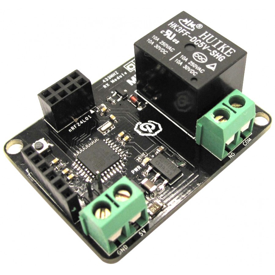
Therefore a small footprint Arduino compatible box of some kind along with an integrated NRF24L01+ module which can support star and mesh topology networks which is ideal for larger numbers of home automation devices. Perhaps a universal interface could be used to have many versions of wireless standards integrated in? Ideally a user could just use a shield if they were not happy with the NRF24L01+.
Quite like this but better overall hopefully.
![]()
Wi-AC Control
An arduino compatible, wireless AC control platform for DIY home automation.