-
Toggle pattern for frequency response
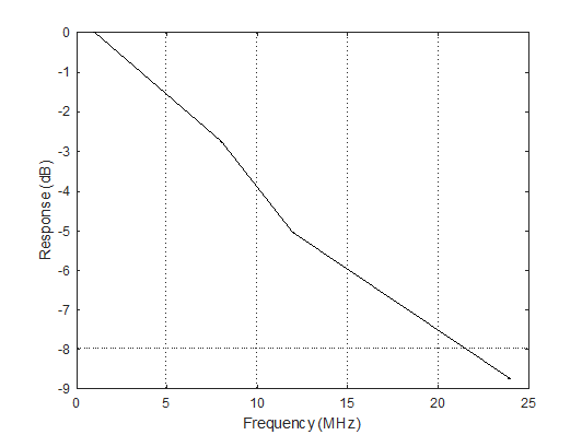
06/17/2023 at 03:29 • 0 commentsNext, I changed the PIO from bit pattern, to toggle. So, a 2 MHz toggle gives a 1 MHz signal. Here is the response that I measured. So, a 3 dB frequency response of roughly 10 MHz.

So, for ~$50 CDN in parts, you can have a 96 MSps, 10 MHz scope with 100 k input impedance.
-
Code - main ideas
06/17/2023 at 03:17 • 0 commentsPlease see the github site for the code.
The main idea is to use the PIO to clock the ADC10080, and grab data from it. So, you use the "sideset" to set the clock line to 1, then set it to 0 as you grab the values on the 10 pins. Do this three times, and push the data out on the FIFO.
@asm_pio(in_shiftdir=PIO.SHIFT_LEFT, autopush=True, push_thresh=30, sideset_init=(PIO.OUT_LOW))
def sideset_test():
    nop()          .side(1)
    in_(pins, 10)  .side(0)

    nop()          .side(1)
    in_(pins, 10)  .side(0)

    nop()          .side(1)
    in_(pins, 10)  .side(0)
The data from the FIFO goes to the DMA. The DMA saves the data into an array, and just loops around and around. Then, you carefully stop the DMA, and then read out the array and process it in your favorite program.
-
Eye diagram for 24 Mbps bit pattern
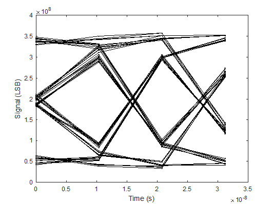
06/17/2023 at 03:09 • 0 commentsSince the ADC10080 was run at 96 MSps, the view of the 24 Mbps pattern lends itself to an eye diagram. Here it is!
-
First Measurements
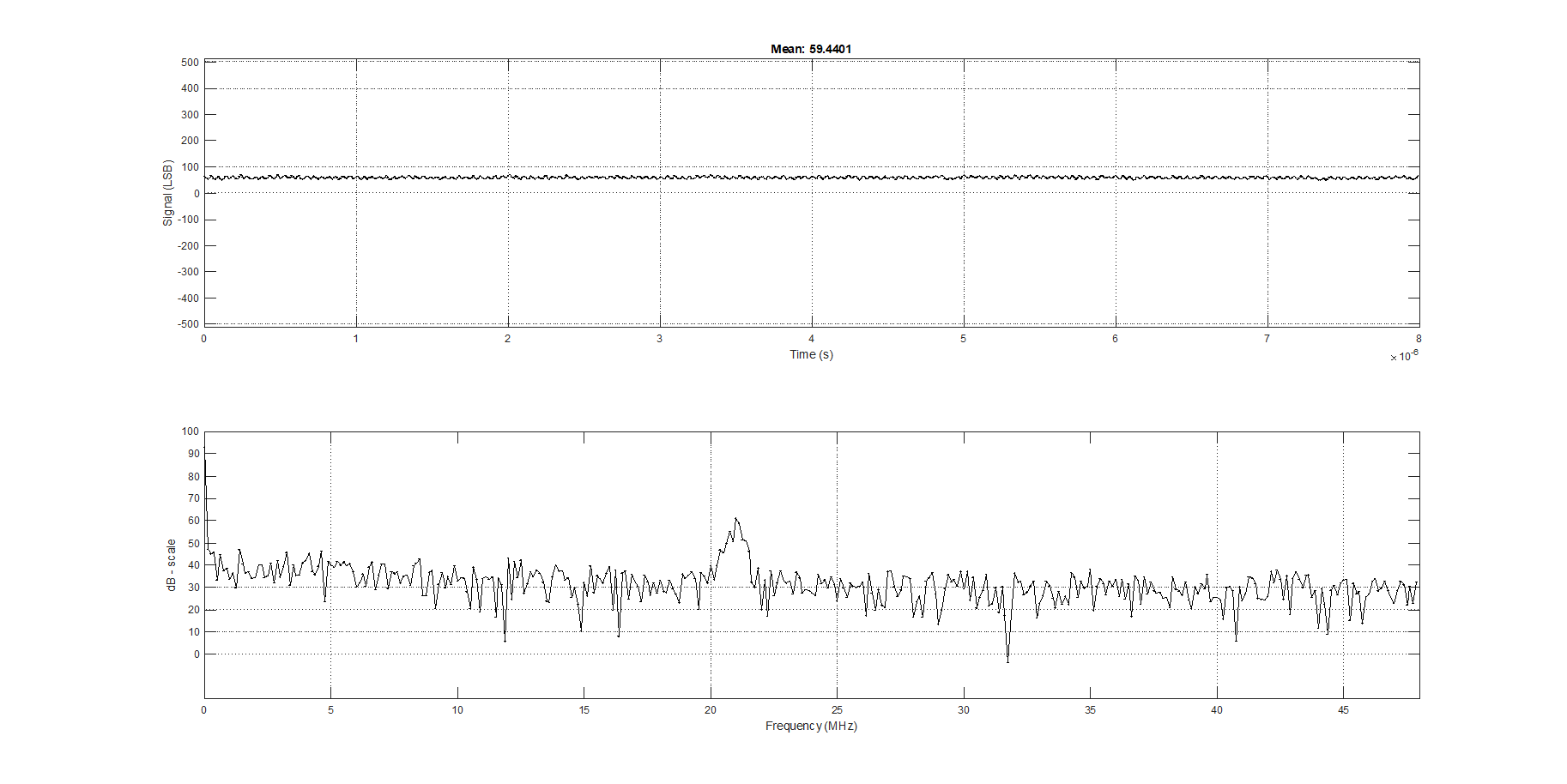
06/17/2023 at 02:59 • 0 commentsThe first measurement I took was connecting the op-amp input to GND.
Using the 16 k resistor instead of an ideal 16.666 k resistor gives an offset of ~59 LSB (I built another version with lower input impedance, i.e., RS 3k, RM 750, RT 1k, RF 430 and RG 270, and the offset is not there). There is also some ~21 MHz noise.
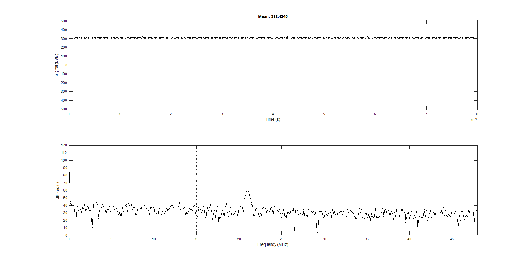
Next measurement was the 3.3V supply.
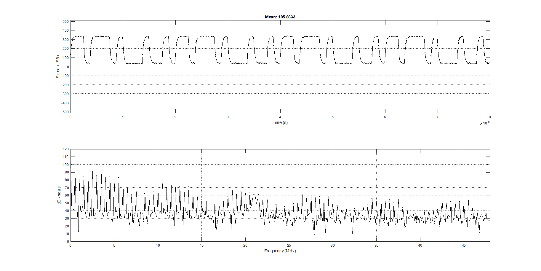
Next, I made a PIO state machine that would output a simple 16 bit pattern: 1011 0111 0100 0100. Then, I set the PIO to run at different frequencies. Here is the view of an 8 Mbps signal:
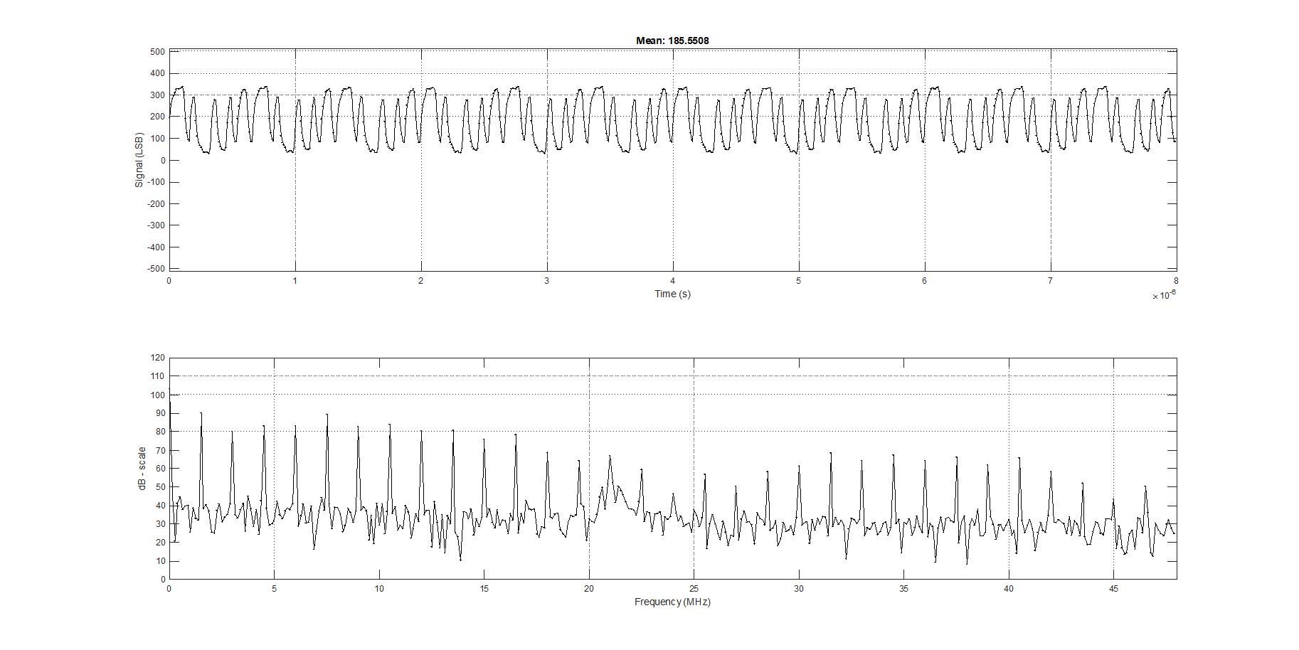
Here is a view of a 24 Mbps signal:
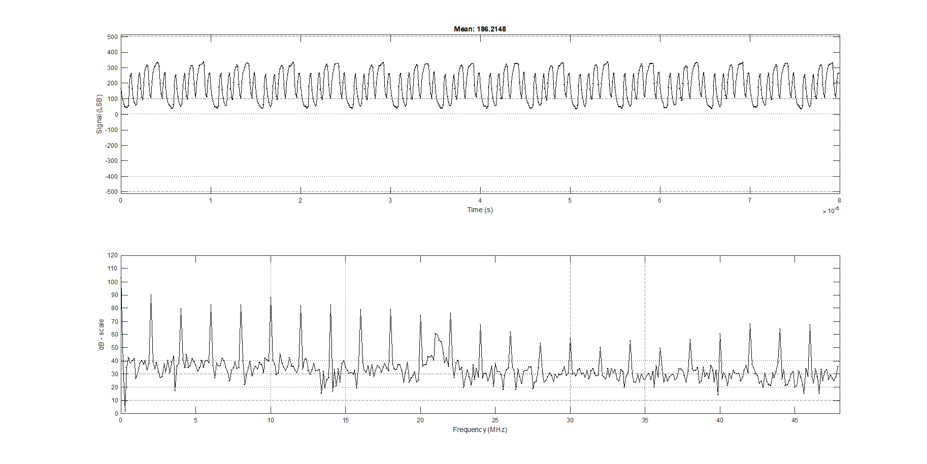
Here is a view of a 32 Mbps signal (getting a little dicey!):
Raspberry Pi Pico Super Simple Oscilloscope
Raspberry PI and ADC10080, works decently for a 24 Mbps signal and has 100 k input impedance