-
1Download visor design
Download the Fusion 360 files from the File section to view the current design of the visor.
-
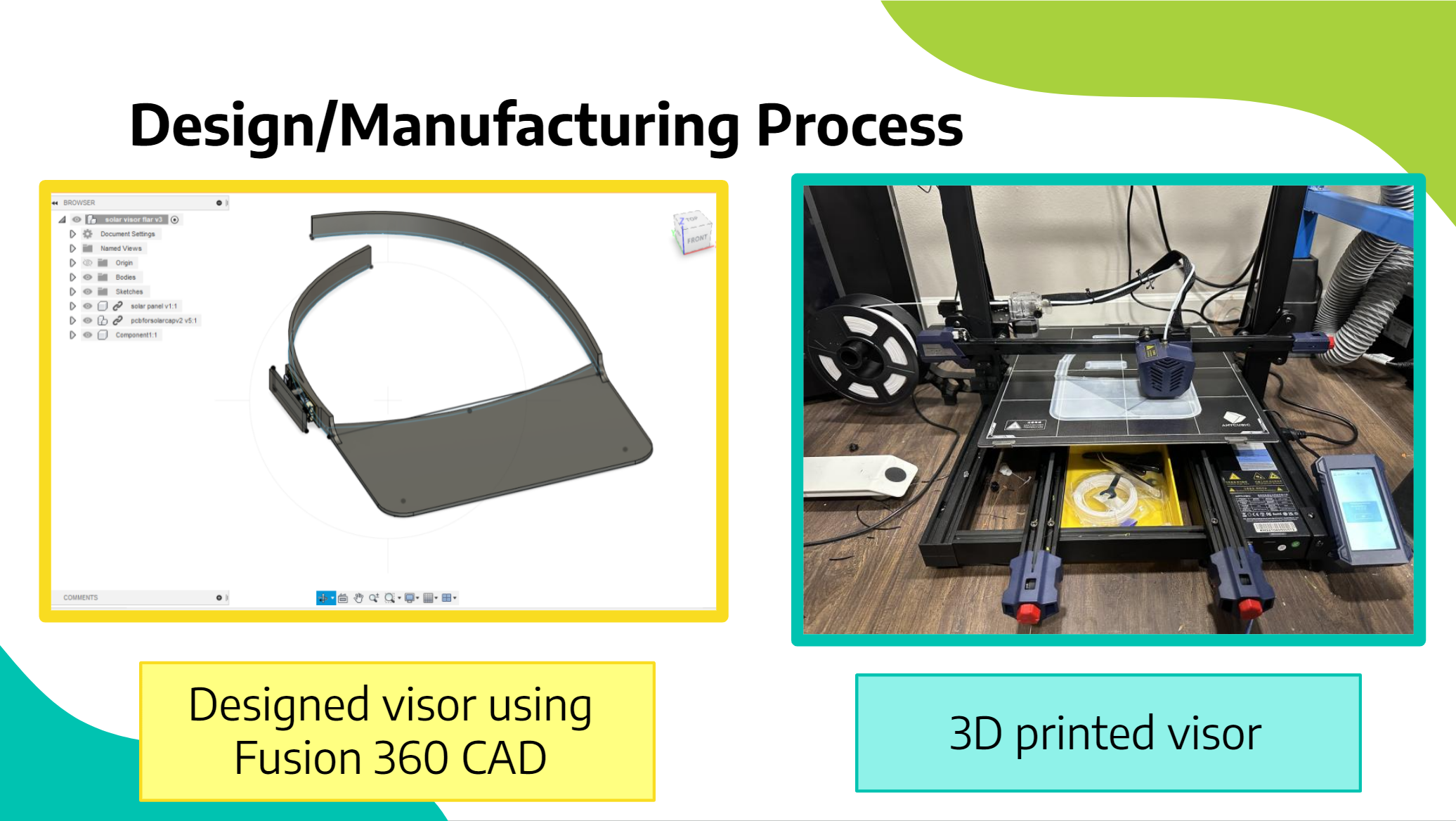
2Open Design
Open the design in fusion 360
![]()
-
3Print
Export the design to STL and then use a 3D printing slicer SW like CURA to slice the model. Then send the design to the 3D printer. (When 3D printing visors make sure to use PETG plastic. When we tried using PLA plastic the visor wasn’t as durable)
![]()
-
4Download PCB design
Download the Fusion 360 files from the File section to view the schematic and PCB design.
-
5Open Schematic of PCB
Open the design in Fusion 360
![]()
-
6Order the PCB and Electronic components
Use the Manufacturing menu in Fusion 360 to export gerber files. Use the Gerber files to order the PCB and SMT Stencil (We ordered from jlcpcb.com). Use the Bill of Materials in files section to order components (we used digikey.com and mouser.com)
-
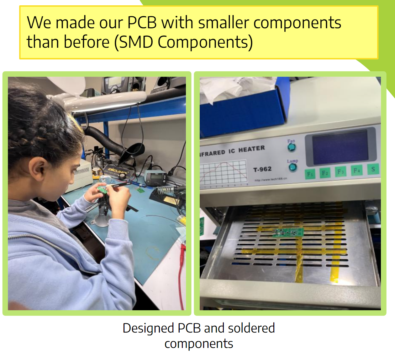
7Solder
Once the PCB arrives, use the SMT Stencil to apply solder paste to the PCB. Then please the SMD components. Use an infrared oven (we used the T962 PCB reflow oven) to solder the components on the PCB. Once the SMD components are soldered, hand solder all the through-hole components like molex connectors, switches and headers.
![]()
-
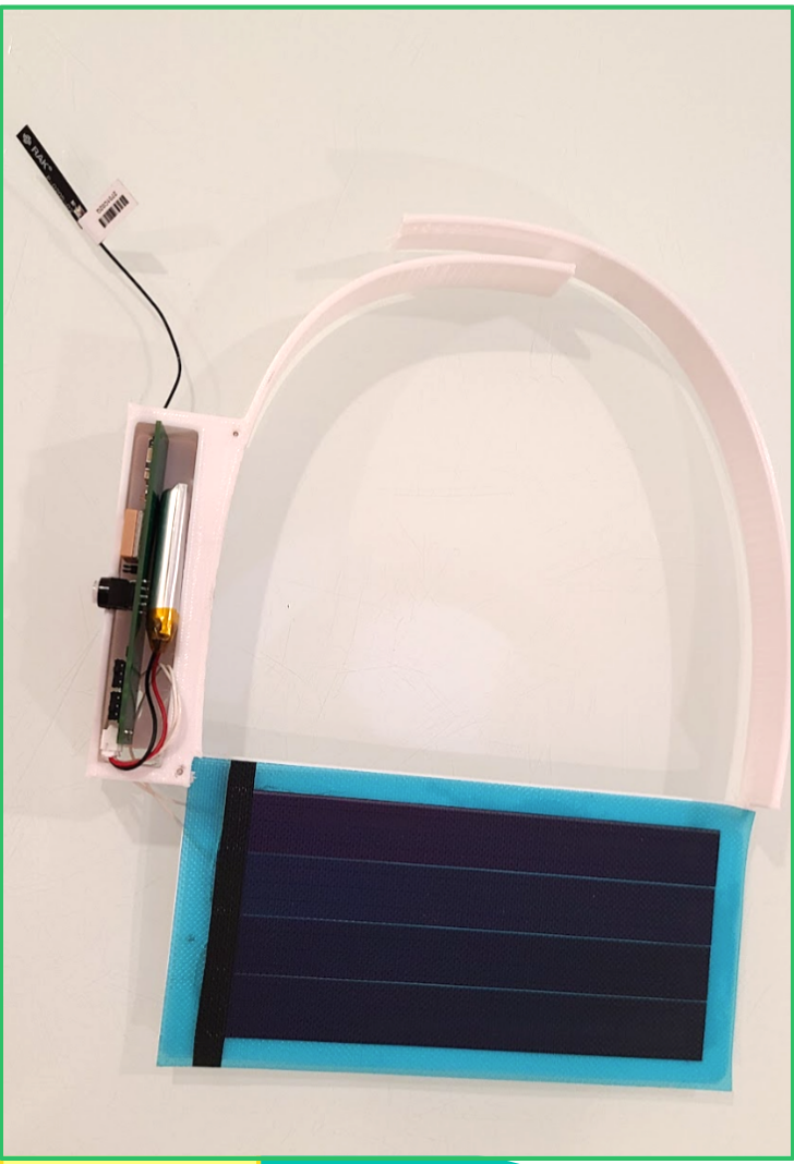
8Assemble the design
Then place the PCB in the enclosure on one side. Make sure the LoRAWAN antenna is plugged into the IPEX connector on the RAK3172.
![]()
-
9Attach solar panel and Lithium battery
Use super glue to attach the solar panel to the rectangular part of the visor. Also attach the battery to the PCB.
![]()
-
10Connect USB->UART adapter to jumper J4
Connect RX, TX and GND lines. Connect USB port to PC.
Solar Powered LoRaWAN GPS tracker + phone charger
An environmental friendly visor using solar energy to charge handheld devices and supports GPS tracking/SOS through Helium LoraWAN network.


Discussions
Become a Hackaday.io Member
Create an account to leave a comment. Already have an account? Log In.