WJCarpenter
-
First light
06/25/2023 at 23:04 • 0 commentsIntegrating an ESPHome device with Home Assistant is simplicity itself. Here's a chart of the power readings from the washing machine (left, s31green) and the dryer (right, s31pink) for a laundry cycle.
![]()
The washing machine goes through a lot of different phases, so it's understandable to see all those ups and downs. The dryer, on the other hand, being heated with natural gas, should be fairly steady. It's just the tumbler motor and a tiny amount of control electronics. I'm not too sure what those spikes are about. They last 1-2 minutes.
The really good news is that both of the monitors report zero power consumption (to 5 decimal places) when the machines are off. That's pretty unambiguous. It's an improvement on my homebrew design, which always seemed to pick up a little noise that needed to be dealt with.
-
ESPHome customization, round 1
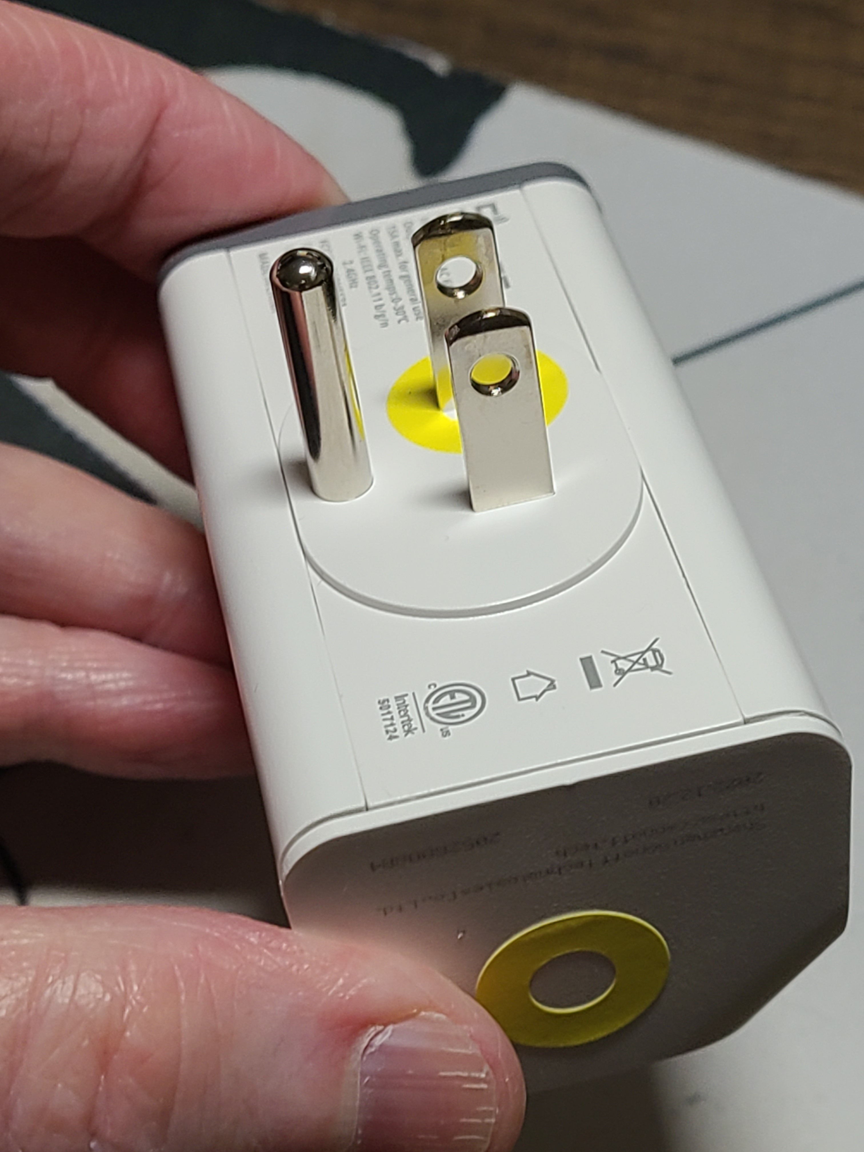
06/25/2023 at 21:58 • 0 commentsI marked all of my S31 devices with different colors so I could keep track of what was what. I have green, pink, yellow, and orange markings. Here's the yellow one:
![]()
I then set about making some initial changes to the ESPHome sample configuration. This will probably evolve a little bit over time. There are already some changes I'm planning to make.
I used a common configuration file that gets included into a configuration file specific to each separate device. For example, here is the one for the yellow S31:
substitutions:
  name: s31yellow
  alias: Yellow
  alias_icon: mdi:cloud-question
  power_on_boot: 'true'
<<: !include { file: s31.yaml.inc}
The idea of the substitution variables is to control configuration of things in the common file, which is here:
# This is a mild adaptation of the ESPHome configuration for Sonoff S31
# smart plug described here: https://www.esphome-devices.com/devices/Sonoff-S31/

# Pin     Function
# GPIO0   Push Button (HIGH = off, LOW = on)
# GPIO12  Relay and its status LED
# GPIO13  Green LED (HIGH = off, LOW = on)
# GPIO1   RX pin (for external sensors)
# GPIO3   TX pin (for external sensors)

# This file is intended to be included from another file that defines
# some configuration choices via substitution variables:
#   name:          the name of this device, appears various places
#   alias:         a functional alias, reported as a text sensor
#   alias_icon:    front-end icon for the alias sensor
#   power_on_boot: boolean, whether to turn on the relay at boot time

esphome:
  name: ${name}
  platform: ESP8266
  board: esp01_1m
  on_boot:
    then:
      - text_sensor.template.publish:
          id: i_alias
          state: ${alias}
      - if:
          condition:
            lambda: 'return ${power_on_boot};'
          then:
            - switch.turn_on: relay
      # give time for all the status goop to stop fiddling with the LED
      - delay: 60s
      - light.turn_off: i_status_led

wifi:
  ssid: !secret wifi_ssid
  password: !secret wifi_password

logger:
  baud_rate: 0 # (UART logging interferes with cse7766)
api:
ota:

# The value never changes except on a firmware update,
# so the update interval is never, and the value is
# published at boot time.
text_sensor:
  - platform: template
    name: "${name} alias"
    id: i_alias
    icon: ${alias_icon}
    update_interval: never

uart:
  rx_pin: RX
  baud_rate: 4800

binary_sensor:
  - platform: gpio
    pin:
      number: GPIO0
      mode: INPUT_PULLUP
      inverted: True
    name: "${name} Button"
    on_press:
      - switch.toggle: relay
  - platform: status
    name: "${name} Status"

sensor:
  - platform: wifi_signal
    name: "${name} WiFi Signal"
    update_interval: 120s
  - platform: cse7766
    update_interval: 30s
    current:
      name: "${name} Current"
      accuracy_decimals: 1
    voltage:
      name: "${name} Voltage"
      accuracy_decimals: 1
    power:
      name: "${name} Power"
      accuracy_decimals: 1
    energy:
      name: "${name} Energy"
      accuracy_decimals: 1

switch:
  - platform: gpio
    name: "${name} Relay"
    pin: GPIO12
    id: relay

# I changed this from a status_led component to a ligth component
# so that I could control it independently of the boring status.
# "inverted" so that it's normall off.
light:
  - platform: status_led
    id: i_status_led
    name: "${name} Status LED"
    pin:
      number: GPIO13
      inverted: true
Most of this is just taken from the sample. The two most important changes are:
- I wanted to be able to control whether the outlet was switched on at boot time. For the laundry machines, the answer is yes. For some other scenarios, the answer could be no.
- I wanted to be able to use the status LED for my own nefarious purposes (which I have not yet decided). I made sure it was turned off at boot time.
Another minor change was to expose the "energy" sensor, which was not present in the sample for whatever reason.
-
Sonoff S31 flashing
06/25/2023 at 21:45 • 0 commentsThere are a million internet descriptions of how to flash the Sonoff S31. I won't cover all that ground here since all I know about it is what I learned from people who went before me.
- This video shows the simple process of taking one apart to expose contacts for flashing. The S31 is extremely accommodating for us nosy snoops.
- The ESPHome devices project provides a sample configuration file here. I have enough experience with this sort of thing that I was able to easily understand all of the ESPHome configuration.
One small hitch is that there is no USB interface in a device like this, so it has to be flashed with a USB-to-serial converter. I have one around here somewhere (in fact, I'm pretty sure I have at least 2 or 3), but I couldn't lay my hands on them when it came time for actually flashing the devices. I came across this description of how to use an ESP8266 board as an impromptu USB-to-serial converter. It won't work with every ESP8266 board, but it will work with (probably) a lot of them. The technique worked with the second ESP8266 board that I pulled out of my extensive collection (aka, junk box). (As the author warns, when using this technique, you want to wire TX to TX and RX to RX instead of the usual cross-over wiring with a real USB-to-serial converter.)
The next inconvenience is that, as you would expect, the S31 doesn't have any connector or pins for its serial port. It does, however, have reasonably sized pads that are clearly marked. You can tack-solder some leads onto those pads and use whatever collection of clips and wires you want to connect those leads to the ESP8266 board. Since I was only going to flash 4 devices, I was OK with using a rat's nest of Dupont wires. I also knew that I could do OTA updates once I got the initial ESPHome firmware flashed. I used M/F jumper wires, tack-soldering the male ends to the S31 pads and using the female ends to the ESP8266. To flash the S31, you have to push its button while applying power to get it into flash mode. So, you do that with one hand. With your other two hands, you plug the USB cable into the ESP8266 board. Yeah, it's tricky, but it can be done if you only happen to have two hands.
Flushed with how easily that went, I desoldered the wiring from the first S31 and tried to wire up the second one. That's how I found out just how easy it is to lift those pads off the board. Grrr.
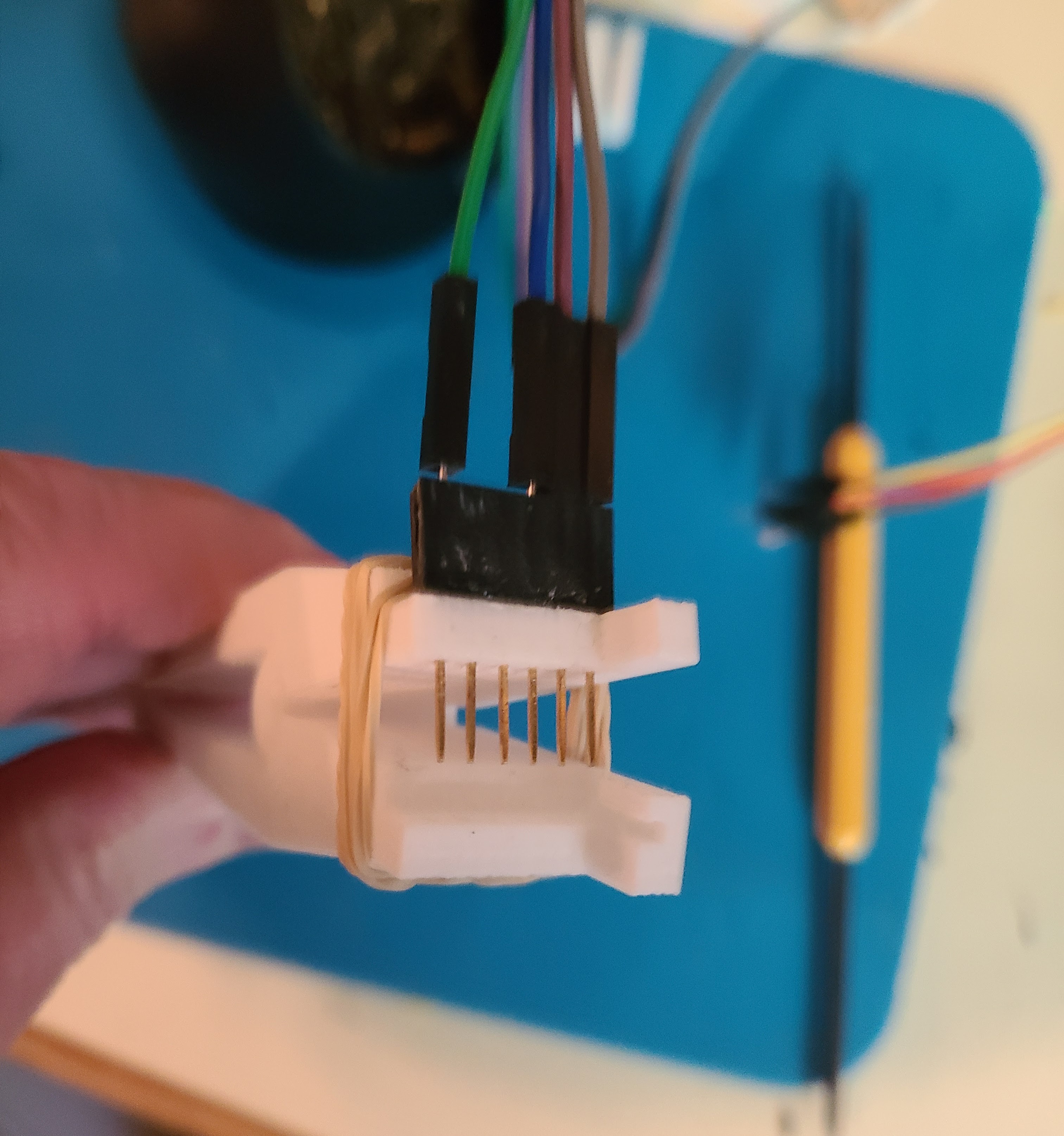
OK, I put that one aside and went looking for some kind of jig or clip or whatever so that I could avoid soldering. I have a couple different kinds of pogo pins on-hand from an unrelated project, so I went looking for something 3D-printable specifically for the S31. I found several without venturing outside Thingiverse. I decided to go with this one since it looked like an easy print and mechanically pretty simple. Instead of using pogo pins, I just used a stacking header glued to the clip. Rubber bands provided some extra squeeze. It was a little tedious to get good contacts on all 4 pads, but I only had two devices to flash, so I stuck with it.
![]()
What about that S31 with the lifted pad? I was hoping maybe there was some OTA way to do that first flash. While looking for that, I came across this mention of a PCB via location that could be used as a solder point. I did that and tack-soldered the other three pads in the usual way. The solder bond to the via was extremely flimsy, but it was strong enough and lasted long enough to get ESPHome flashed.
-
Power monitoring
06/25/2023 at 20:55 • 0 commentsFirst up was seeing what's going on with power monitoring gadgets these days. I knew there were a lot of smart outlets available. I already have several. A couple are hard-wired into the walls, but most are plug-in type adapters that I can move around. Although I have a lot of these, I only use a couple (aside from holiday time, when I use them to turn the decorative lights on and off).
I was amazed at the variety of smart outlets that also include energy monitoring. I was further amazed at how reasonably priced they were. I went on a web windows shopping expedition with the optimization inputs of price, company reputation, and ease of integration. After clicking around for an hour or so, the easy choice for me was ....
The Sonoff S31 is an aesthetically pleasing smart outlet with power monitoring. A pair of them can be plugged into a standard US duplex power outlet. (Its sibling, the S31 Lite is cheaper but does not include power monitoring.) Sonoff is popular in the DIY community. The S31 is widely available for under US$10 (I bought a 4-pack for under US$40). It communicates over wifi. This article, though a few years old, has a lot of good technical detail about the S31.
Perhaps the most important thing for me was that the controller inside is an ESP8266, which meant it was pretty likely that I could put ESPHome onto it. Even without being completely sure, I ordered some and waited.
Laundry monitoring
A collection of notes and pointers for the usual laundry monitoring project.