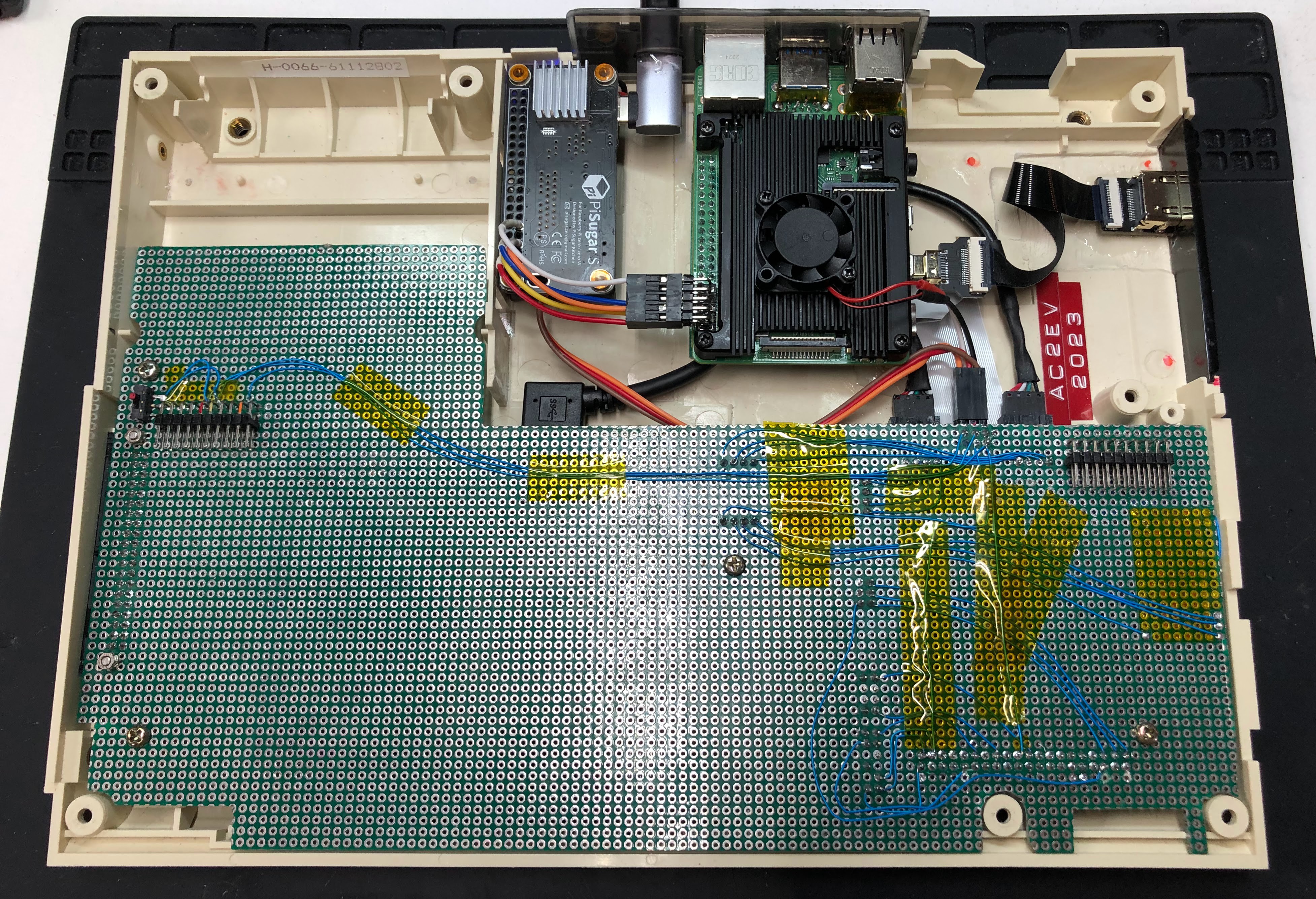
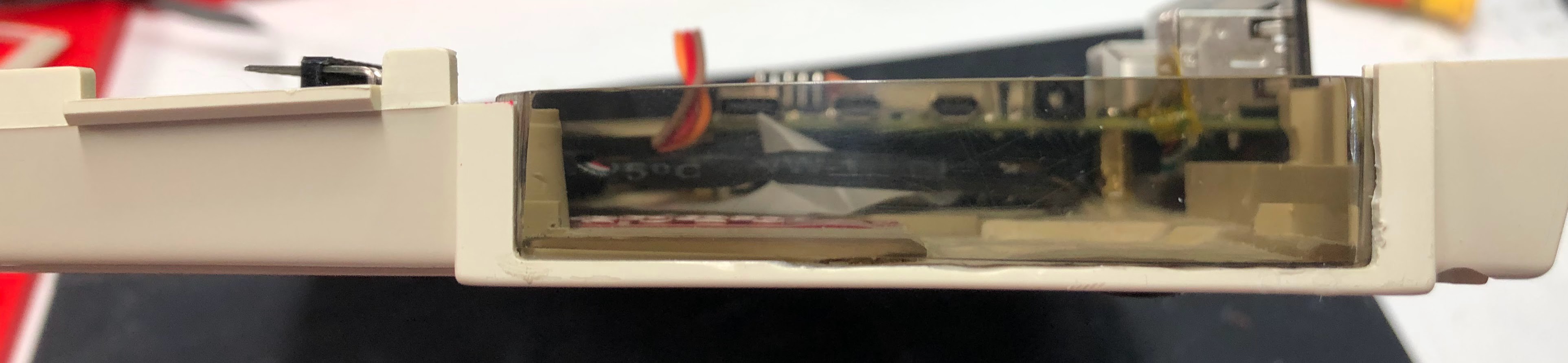
One last pic before I button it up. Temps topped out at about 63C/145F according to the built in CPU temp sensor. A little toasty. Might need to increase ventilation as it's almost against the LCD.
Got a different right angle USB C connector. The new one is 22mm rather than 19.5mm. That gave me the length I needed to fit into the acrylic. It shifted a bit during cure but looks good.
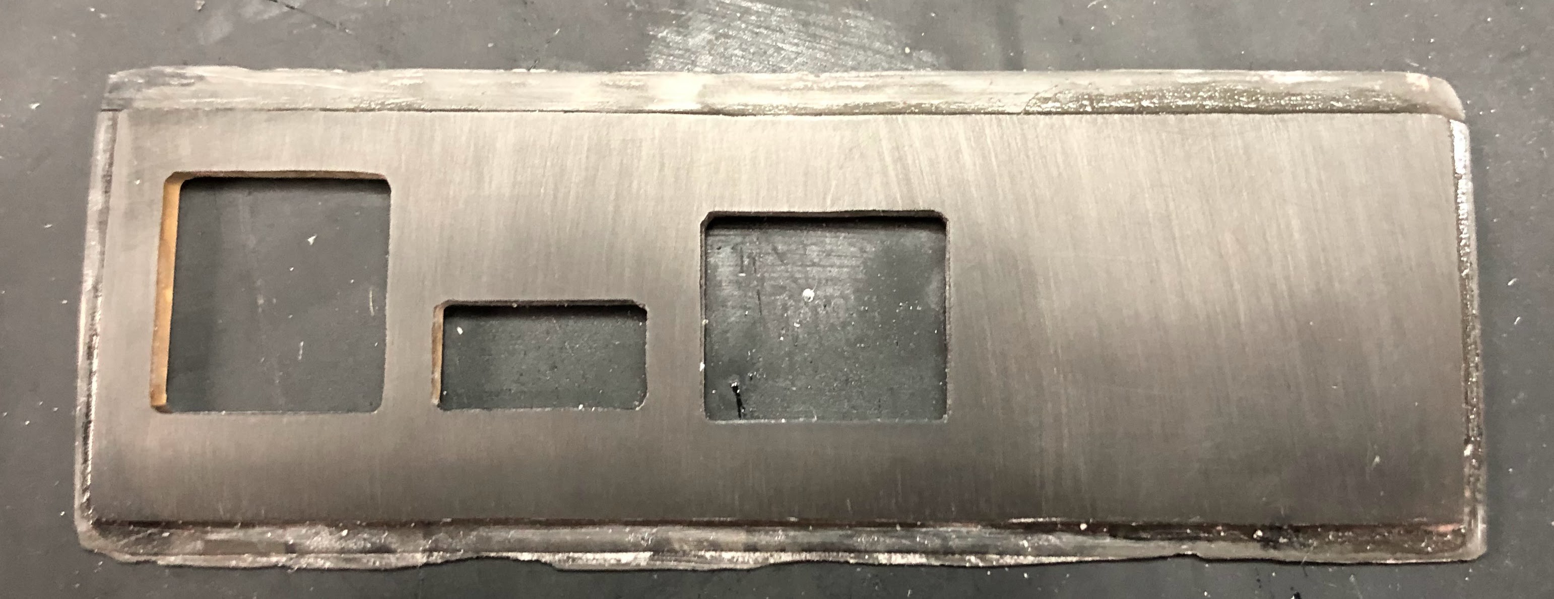
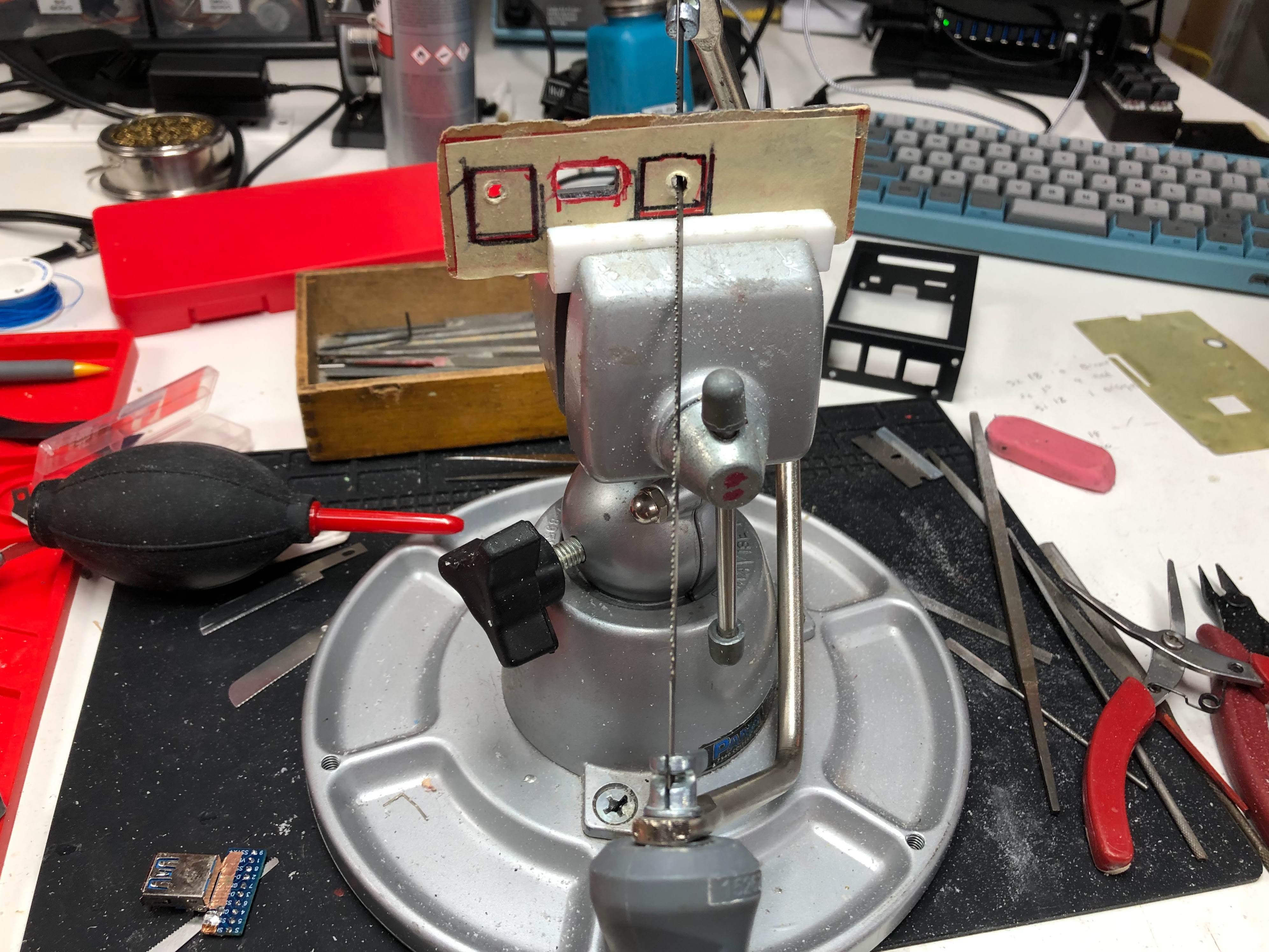
When we last visiting the intrepid engineer he was busy sanding. He's still sanding.
After the polishing there was much rejoicing!
I'm tempted to add some little people and some lights....
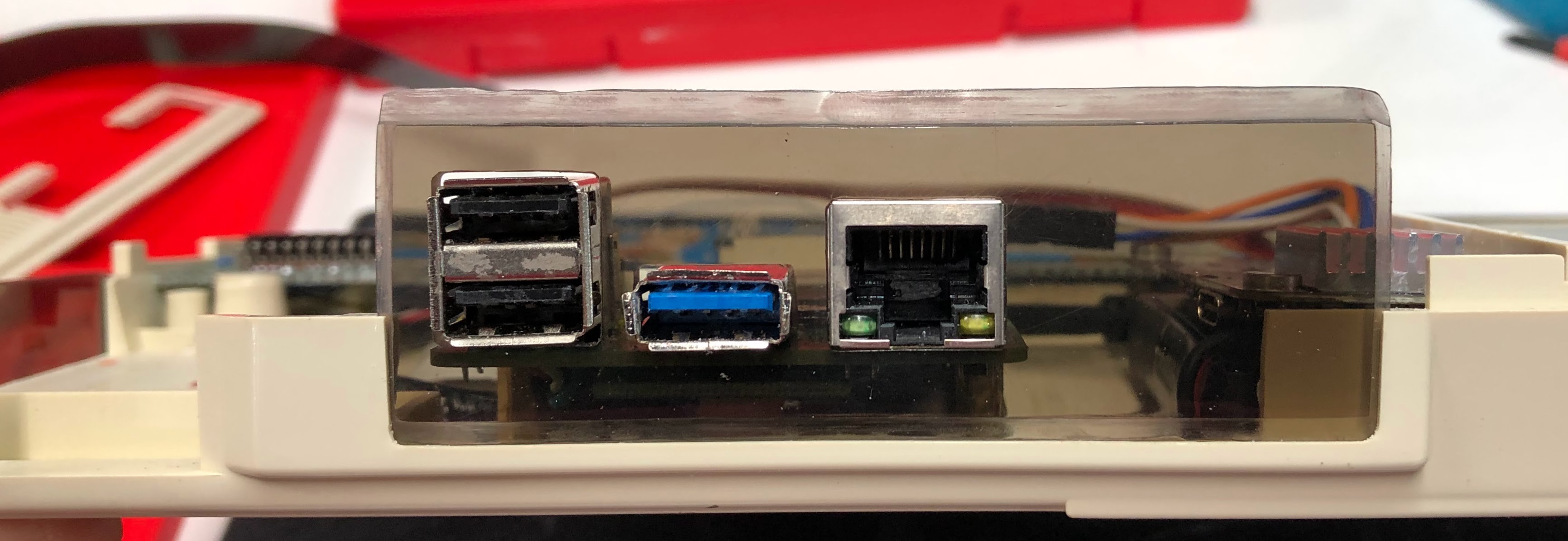
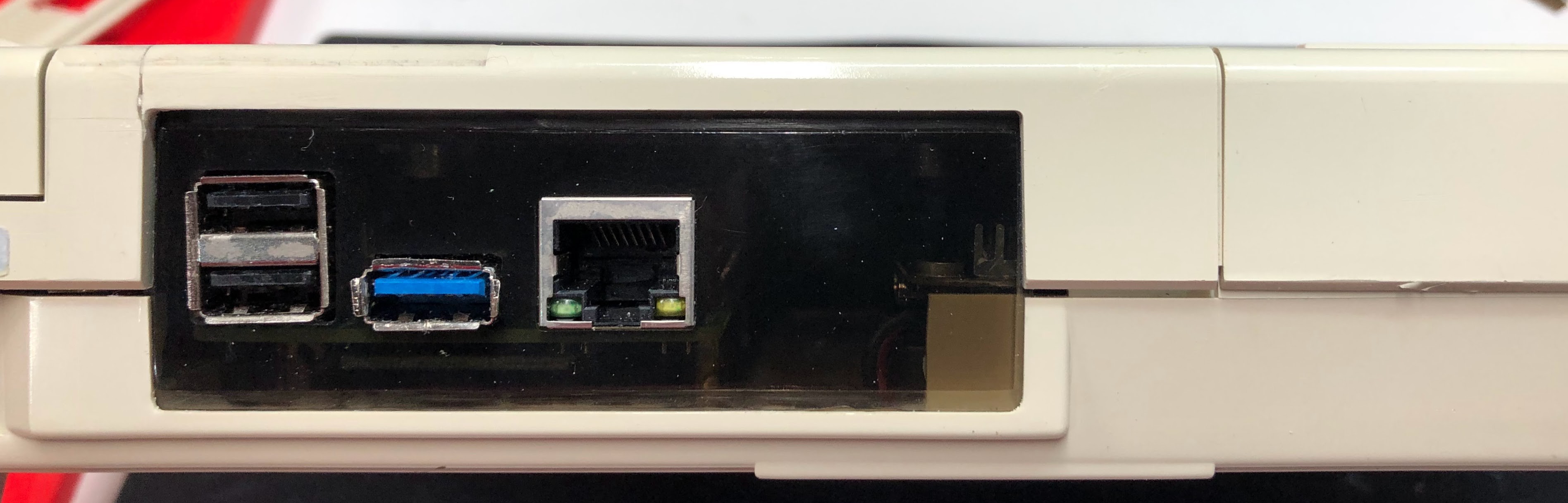
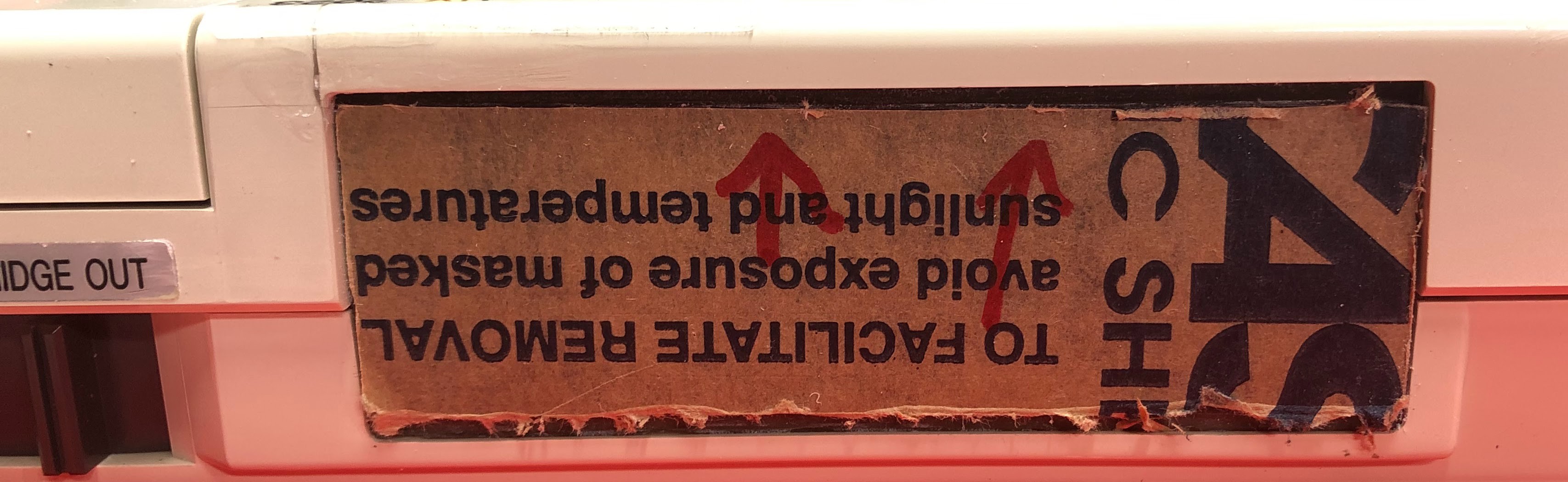
Full disclosure: my cutting and sanding wasn't perfect. I found it easier to re-glue the Pi then try and make a new faceplate. It's lines up 'perfect', just like I measured, yeah. I don't like that the USB 3.0 port sticks out so much. I'll go back and fix that, eventually.
Still need to add the USB C power for the UPS and the HDMI port but it's 99% done.
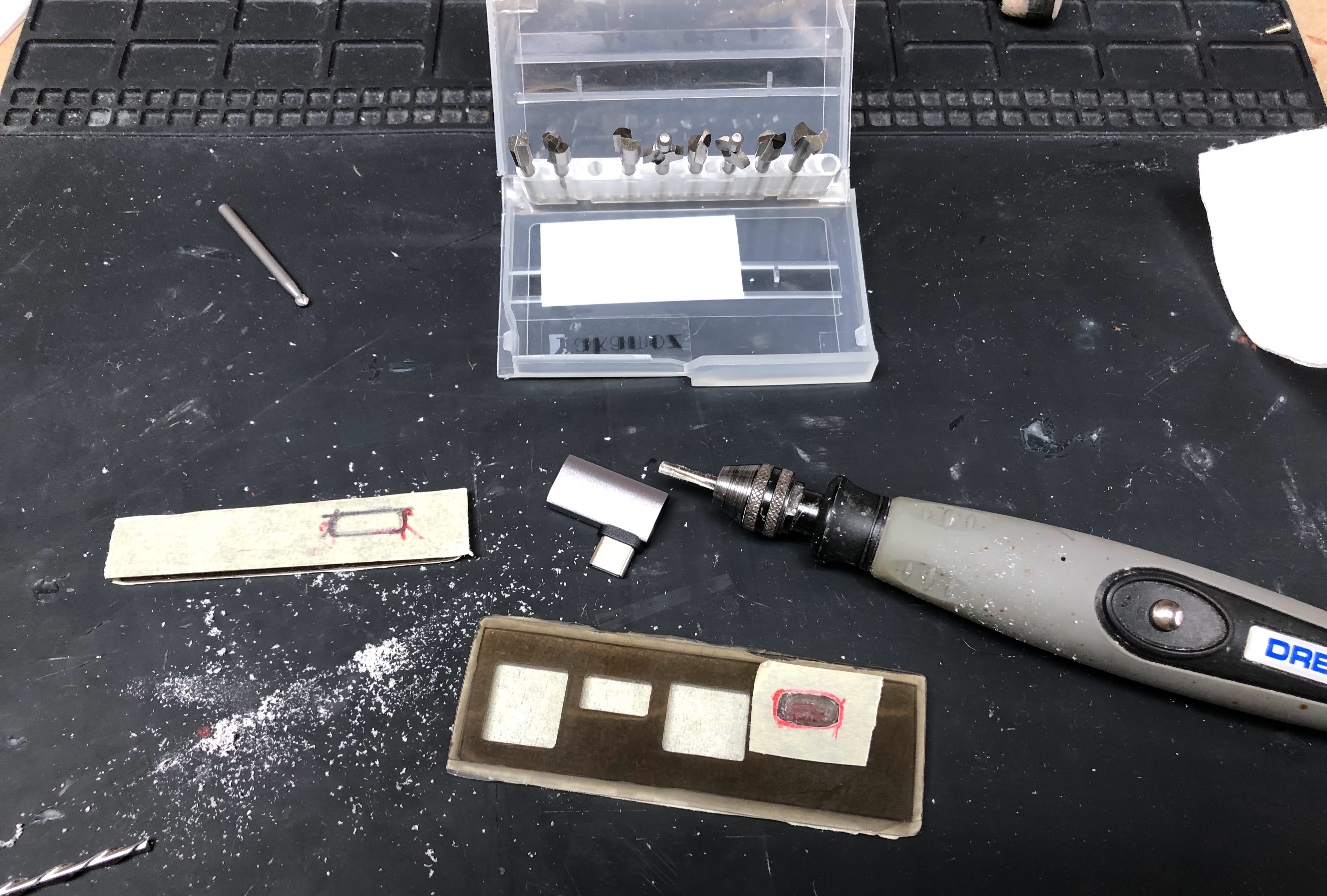
Today we spend some time cutting, shaping, and sanding the acrylic to fit. Did I mention it requires sanding? It does, a lot of sanding and fitting. Then we start polishing. 3000 grit to 10,000 grit paper. When you're done with that then it's time to buff it with Novus #2.
I used a rabbet bit to somewhat carefully cut the rabbets. I'm not patient so it was a little rough.
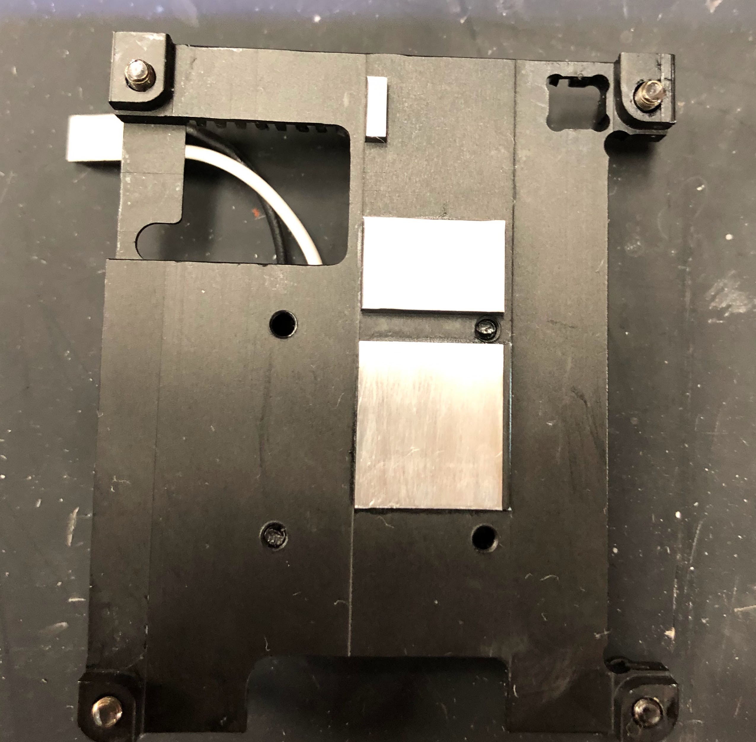
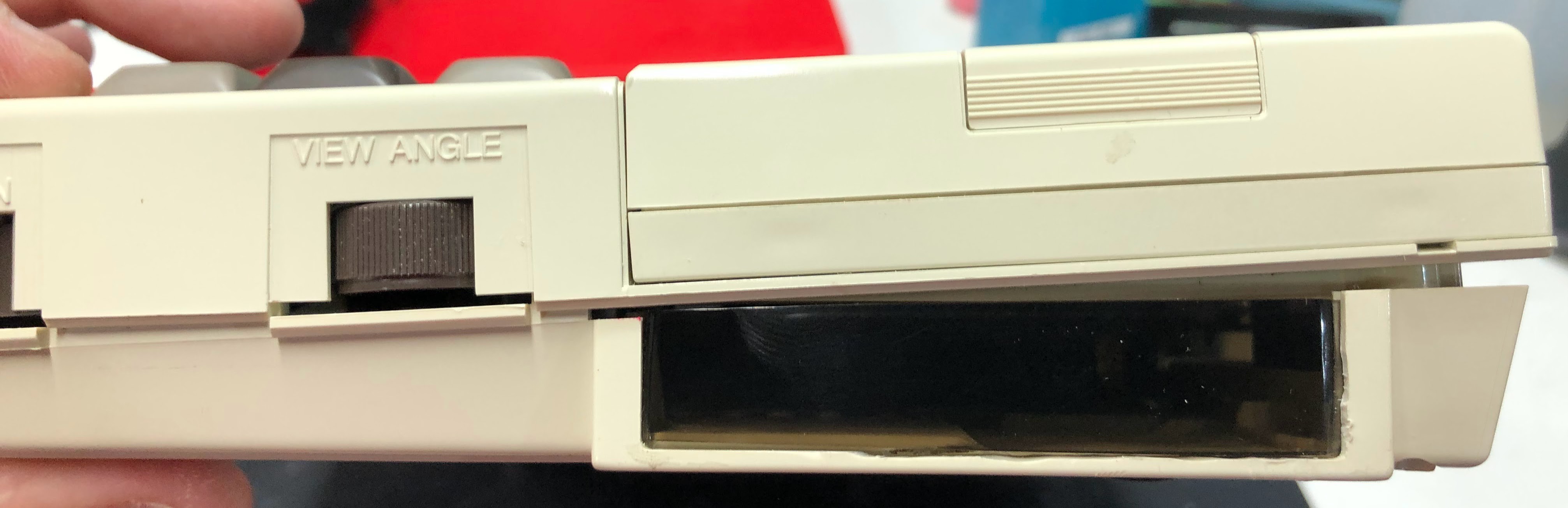
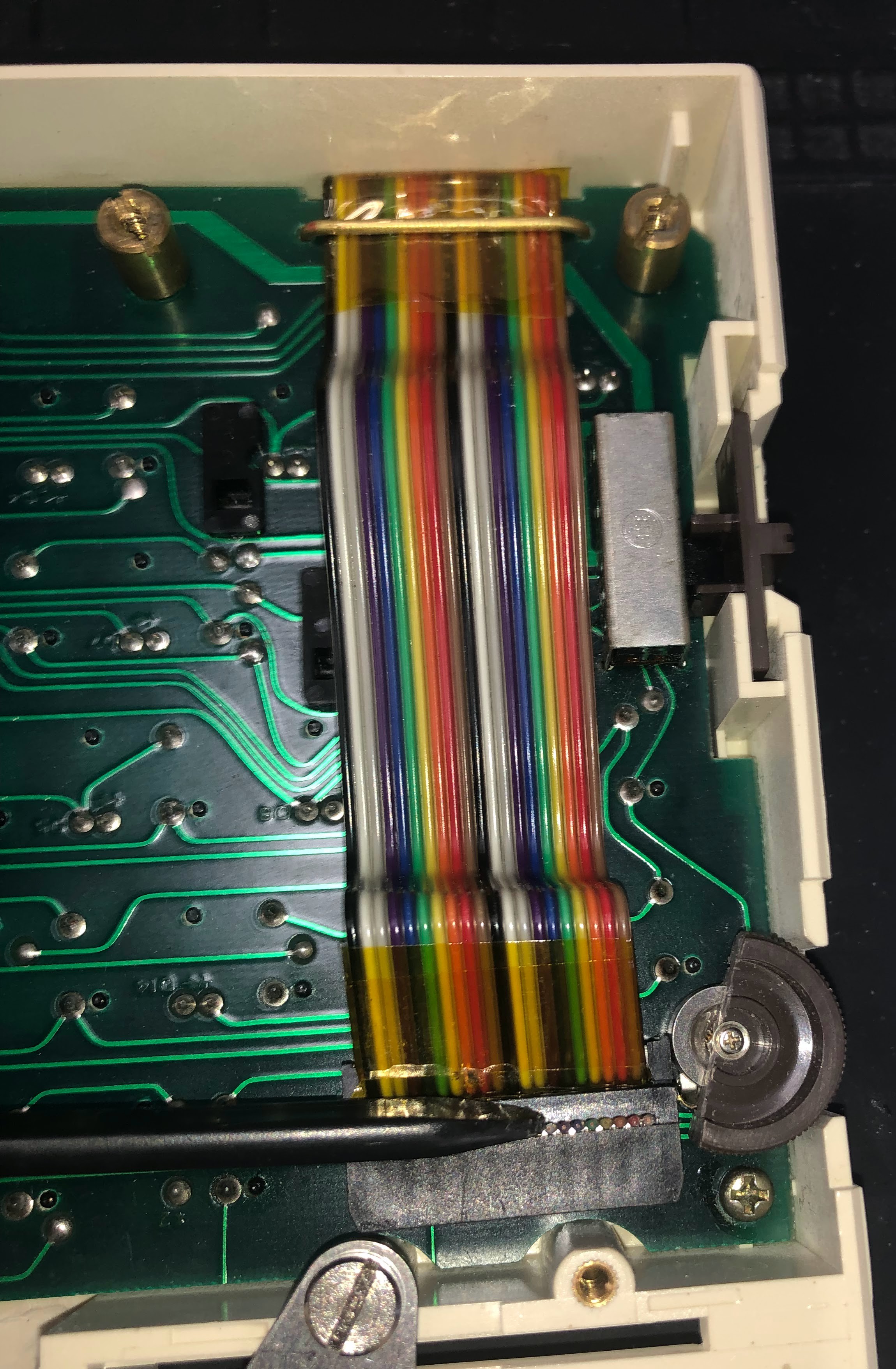
At first I wasn't sure how I was program the 'view angle' adjustment. To be honest I'm still not sure what I am going to do with it. However with the new keyboard cables soldered in place I found that I didn't have space for full rotation of the potentiometer. I ended up removing half of the thumb wheel to get it to fit. This presented me with a thumbwheel that only slightly moves up and down. The connector acts as a stop when everything is connected. I think this is serendipitous and will probably turn into something cool.
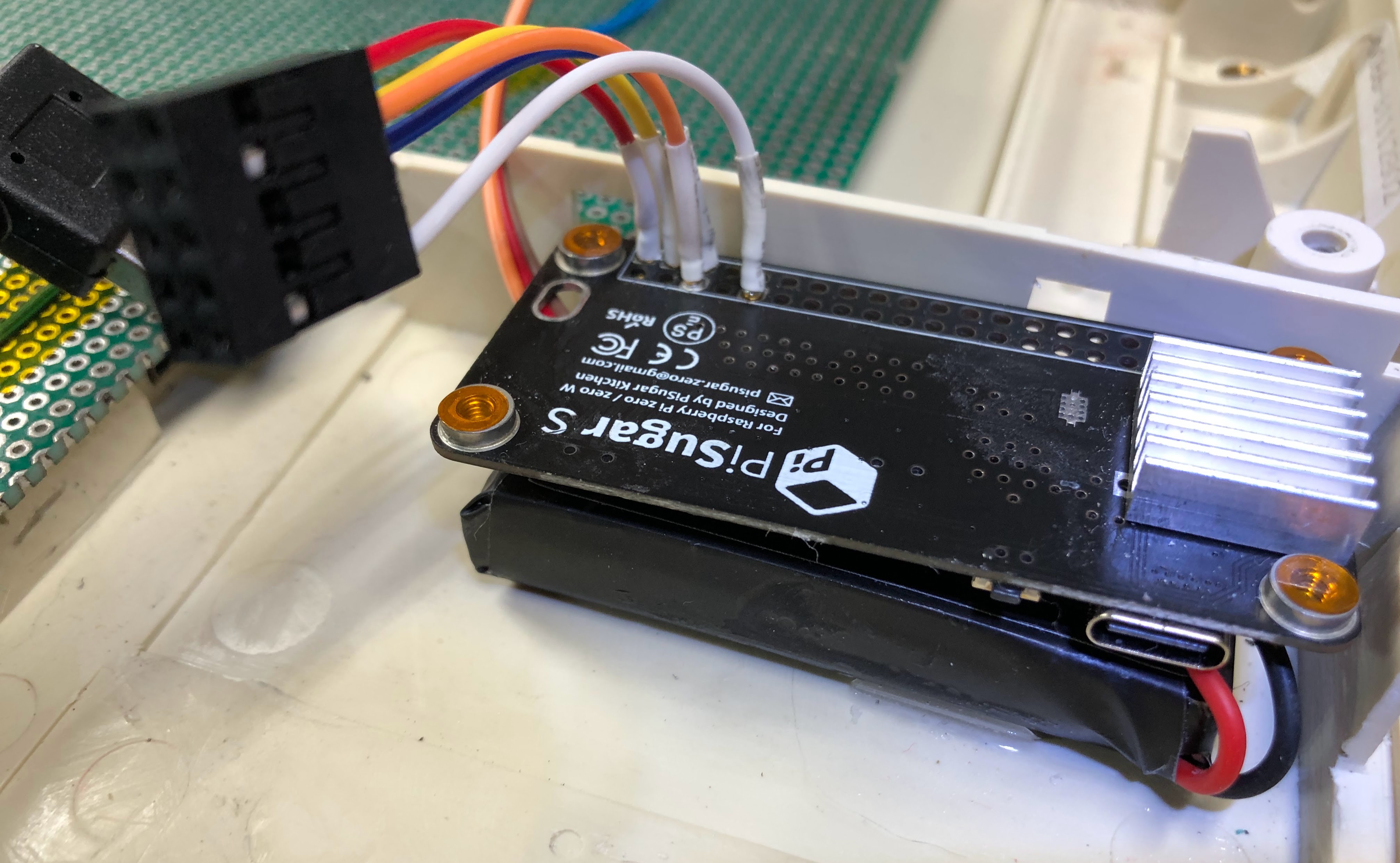
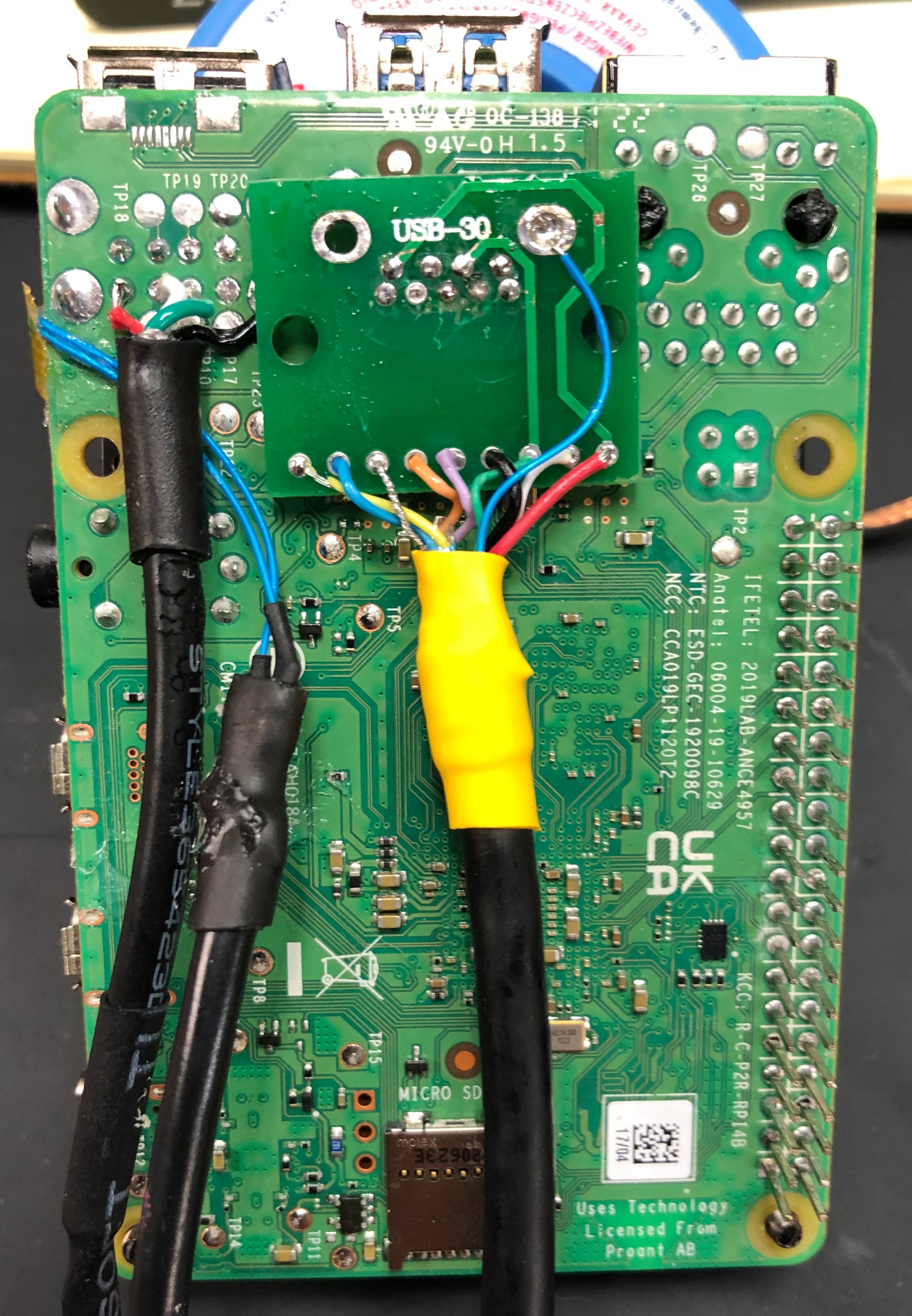
For the USB 3.0 to the SSD drive I removed the stacked usb port and added small jumpers to a USB 3.0 breakout. The breakout then goes to a right angle USB 3.0 cable. The wiring is right to left with the red wire on the right being pin 1 (VBUS).
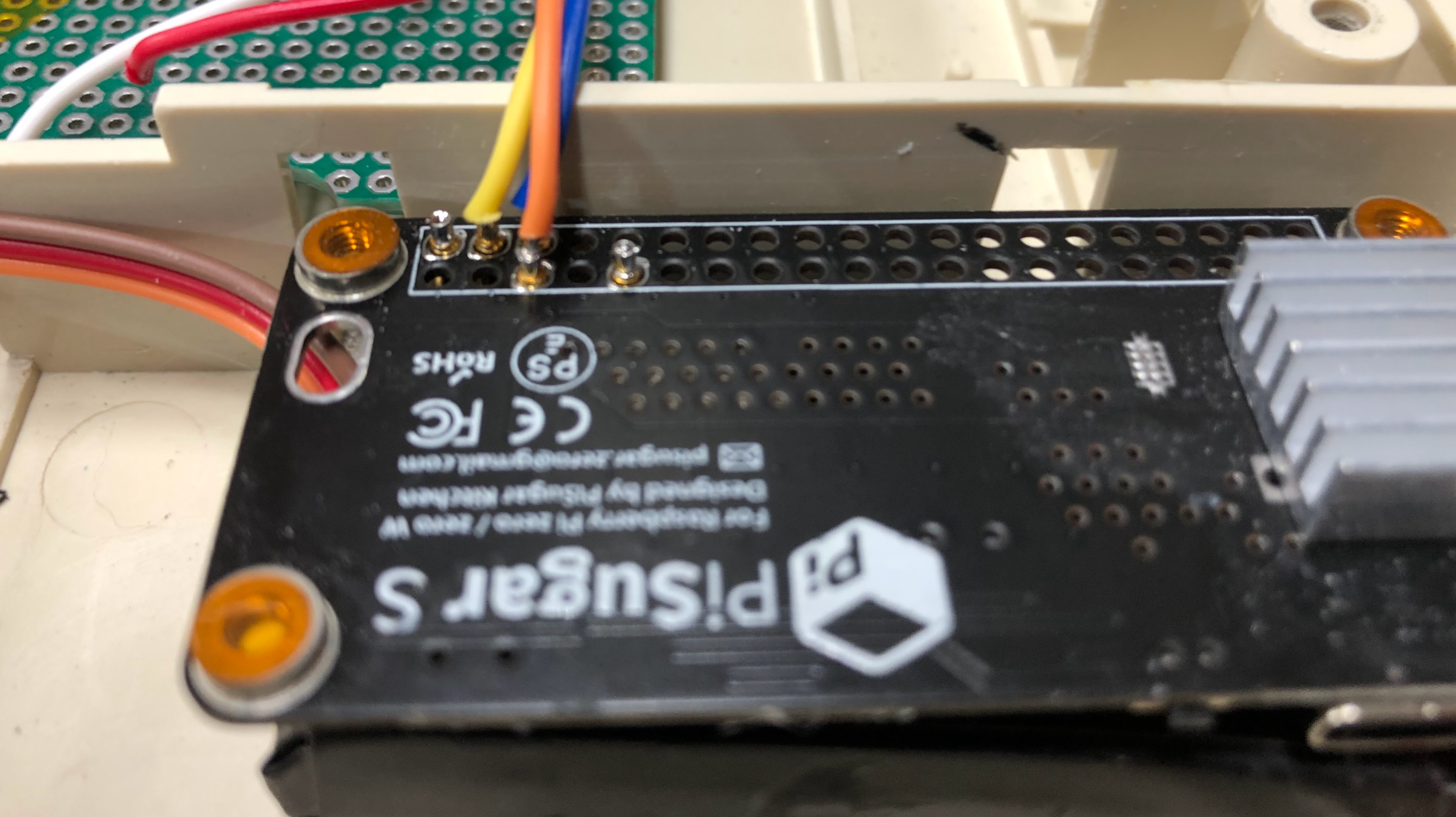
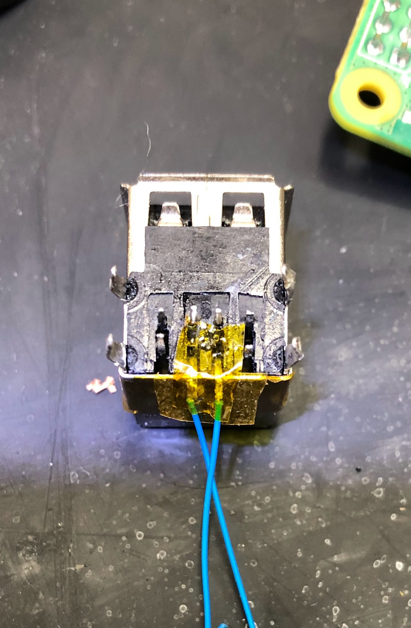
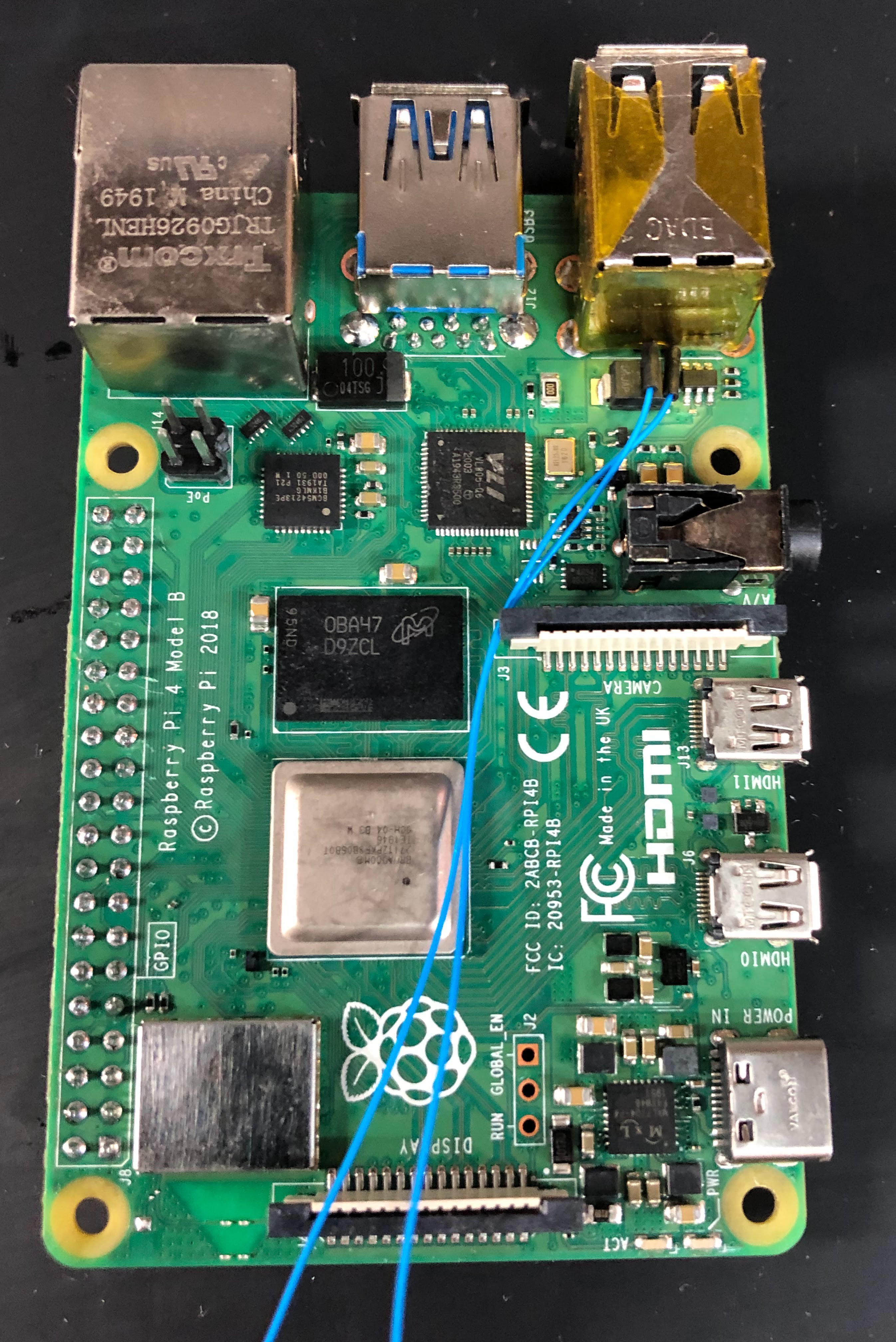
You can also see how I highjacked the USB 2.0 port. The usb 2.0 stack was removed and the data +/- pins we're carefully lifted and soldered to some prototyping wire (30AWG). It was then very carefully re-soldered into place.
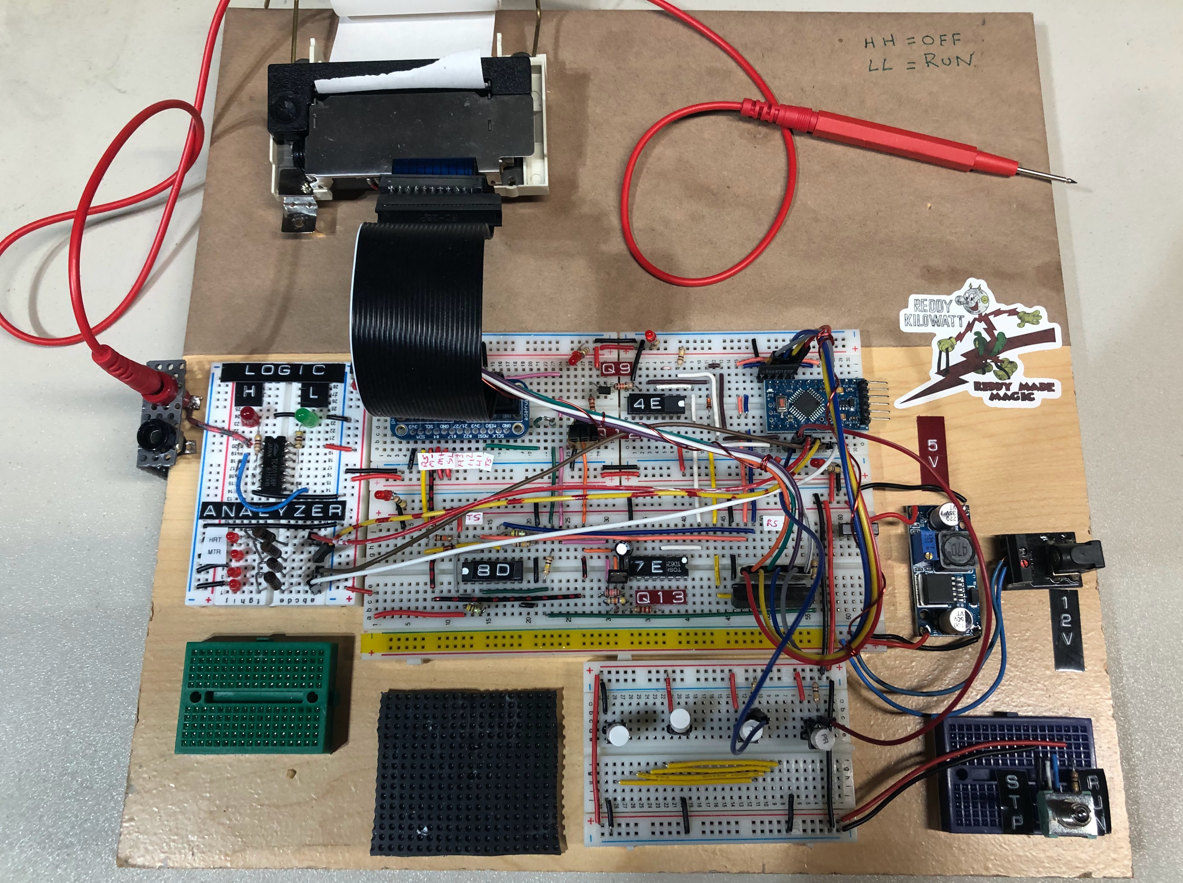
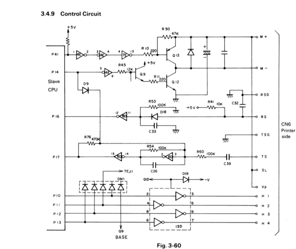
The printer is currently on bread board. I've got a small Arduino to handle printing. Right now I've got it working up to the point to put dots on the paper. It runs the motor, counts the pushes, goes to stability and sends the signals to print but the solenoids to fire. I can manually activate the solenoids with a pushbutton and I get ink on the paper. I think the Arduino may not be able to source the current to actuate the solenoids. Still looking into this. The schematic is also there. Once I get the printer working I'll think I'll set it up on the Pi as a serial printer.
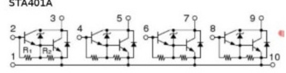
The STA401A should be doing all the heavy lifting. So I'm not sure what's going on. I'll have to hookup the analyzer to it and take some voltage and current measurements of the the actual circuit and mine.
 Don
Don