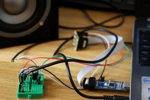
The audio inpus (L+R) are fed through a 10uF decoupling capacitor to a voltage divider that provides a bias of approximately .55v. The 10uF cap and 560 ohm resistor act as a high pass filter, with the cutoff frequency at ~28Hz. If I had to do it again, I'd put a smaller value capacitor on there to raise the cutoff frequency since the amp is prone to distortion on the lower frequencies.
The signals are then fed into the attiny85 via pins ADC1 &ADC3. The ADC is setup using a 1.1v voltage reference since line inputs are typically ~1v. Also, the ADC prescaler is set at 16, giving the ADC clock a frequency of 500m
kHz. Anything over 200khz is recommended to use only 8-bit accuracy, as 10-bit accuracy requires more time. The ADC is started, using the ISR to change the channel that is read, switching from 1 to 3. One value is stored as OCR1A, the other as OCR1B.
Timer1 is setup using PWM1A and PWM1B, set to turn on the corresponding pins when a compare match with OCR1A and OCR1B is made, and then clearing them when the timer reaches 0. Once setup, this is done in hardware, which aids in the reliability of the amp. This causes the pwm frequency to be proportional to the input(s) amplitude.
I did not use a filter on the speakers, but it is highly recommended to filter out the 50% duty cycle 32.5kHz carrier signal.
 George Gardner


 pierrep
 zst123
 CNLohr
 Łukasz Podkalicki
Here's an earlier project: https://hackaday.com/2012/09/05/70-watt-amp-uses-an-attiny/ and here's one that seems to inspired by this: https://hackaday.io/project/163958-attiny13-8bit-mono-class-d-amplifier.
Thanks for sharing!