shlonkin
-
A much simpler way of doing it
08/24/2015 at 13:47 • 0 commentsI tried something different. As much as I like the idea of the speed control, I decided to just make something that works. If I like the hobby enough, I'll probably just buy a commercial lathe. But fear not! I'm still building my own.
This new version is very different and lacks the defining feature of this project(electronic speed control), so I wrote it up as a separate project here: https://hackaday.io/project/7408-a-simpler-cheaper-lathe
Enjoy.
-
Attempt 2 problems
04/19/2015 at 10:36 • 0 commentsI told you I had never worked with AC motors. Cut me some slack.
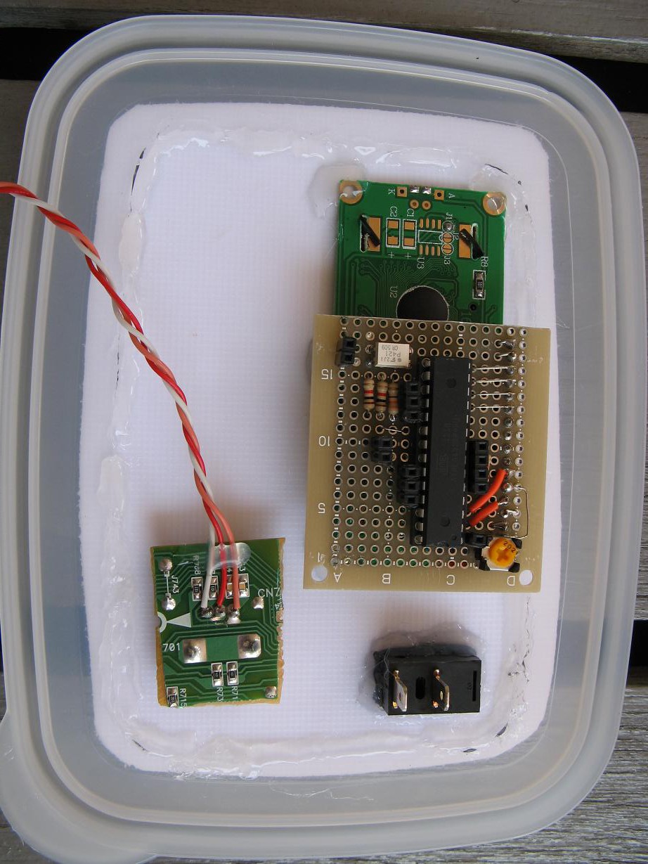
I built the circuitry and tested it out.
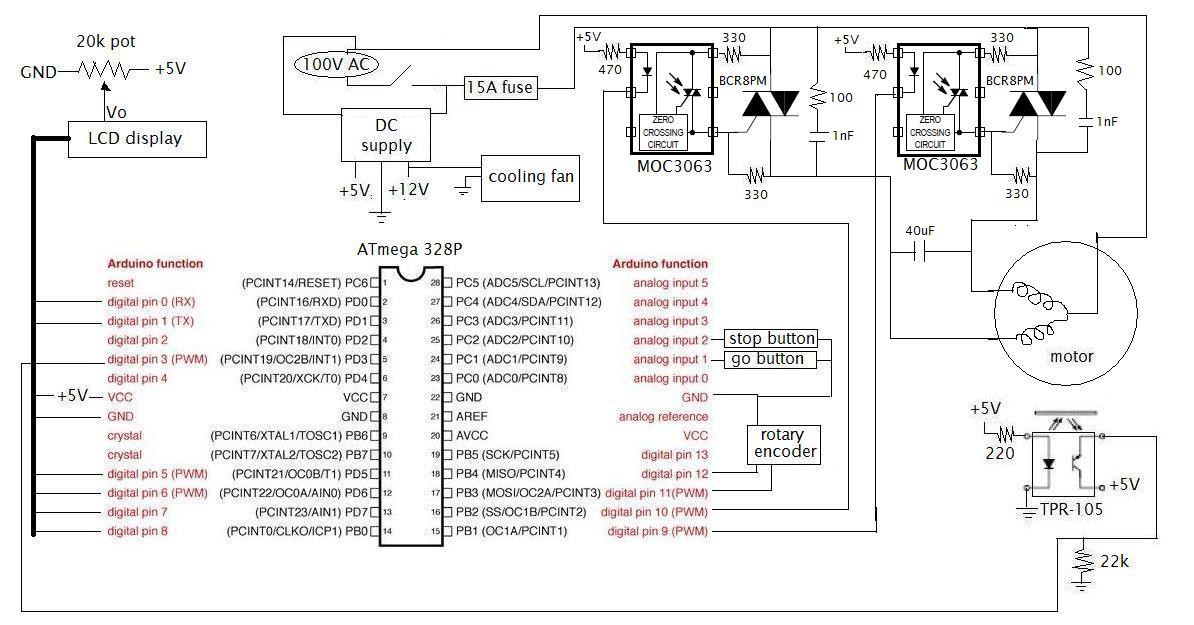
![]() The controller doesn't use regular PWM. Rather it switches on full 60Hz cycles. Thanks to the MOC3063 drivers this switching occurs at zero crossings. For example a half power setting would switch on every other cycle.
The controller doesn't use regular PWM. Rather it switches on full 60Hz cycles. Thanks to the MOC3063 drivers this switching occurs at zero crossings. For example a half power setting would switch on every other cycle.Things seemed to work ok. Sort of. But I noticed that at low power the motor was not so smooth and something just seemed wrong, so I did a little more research. I guess the motor was designed to spin at one particular speed and the right way to control the speed is by changing the AC frequency. It's not an impossible challenge, but I'm currently lacking the free time and motivation to delve into it. I also considered just building the thing with a one speed motor, but that kind of defeats the mission statement of the project.
Plus, the more I learn about wood lathes the more tempted I am to actually buy a proper one and try my hand at wood turning. Of course I would like to try my hand a few times before investing the large sum of money, so I'm keeping my eyes open for such an opportunity.
-
New motor, time to redesign
09/07/2014 at 12:40 • 0 commentsAfter a few nervous tests with some wood, I've decided that this motor just isn't a good choice. As you pointed out in the comments, vacuum motors are designed for high speed and low torque, which is just the opposite of what I need. I thought I could get away with it if I made a nice controller, but I changed my mind and set out in search of a better motor.
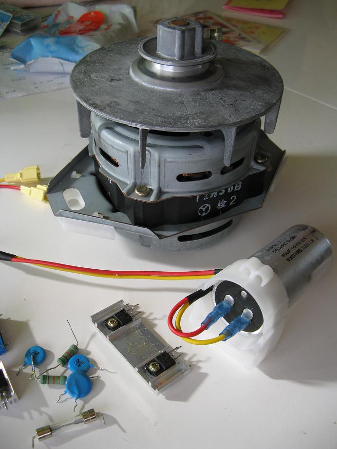
I was fortunate enough to get my hands on this very clean washing machine motor and accompanying circuitry.
![]()
But with this new gem that is designed for low speed and high torque I will make another attempt at a wood lathe. Unfortunately, since this is an AC brushless motor, I will have to completely redesign my driver circuit. I am planning to use the triacs from the washing machine along with some MOC3043 chips to drive them. I'm still doing my homework to figure out a good design since I've never driven AC motors before.
In addition to that, I will have to redesign the whole interface between the motor and wood. I salvaged the other pulley and belt as well, so I will probably make use of them. I'll post again when I have a working design.
-
Mechanical bits and a control panel
07/29/2014 at 13:16 • 1 commentI spent some time working out the more lathey parts. By that I mean the structure and spur centers. It would be easiest to just show you what I did.
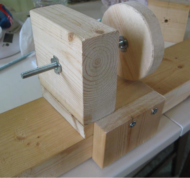
This is the moveable center that slides along a 2x4 and can be clamped in place:
![]()
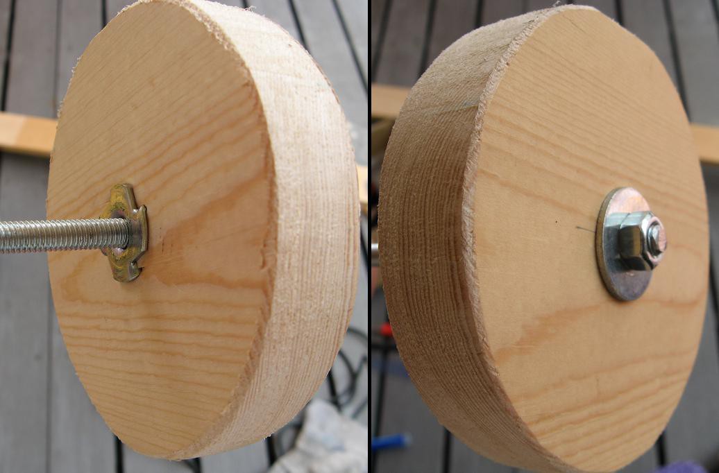
The circular knob was cut with a jigsaw using a hackaday SPACE coaster as a template. Did you know that those coasters are exactly as wide as a 2x4? I'm pretty sure that was a coincidence. This picture shows how I attached a 6mm threaded rod.
![]()
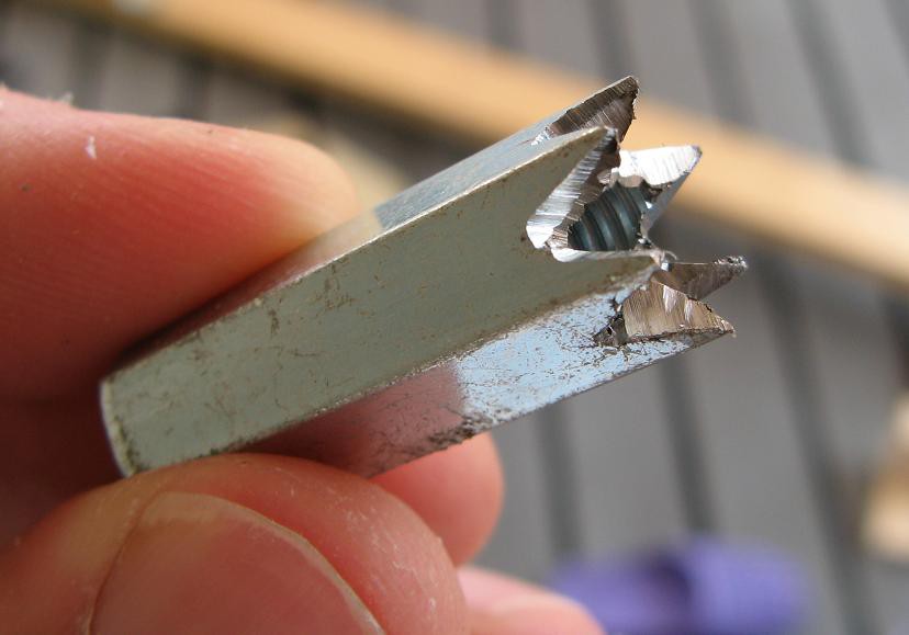
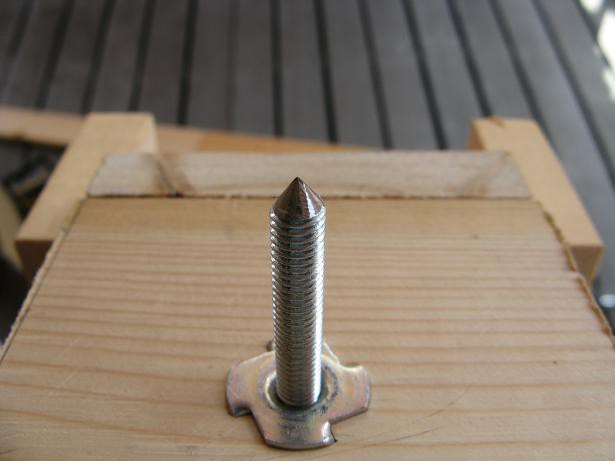
Next was the live center which consists of a long 6mm nut that I modified with a cutoff wheel on an angle grinder.
![]()
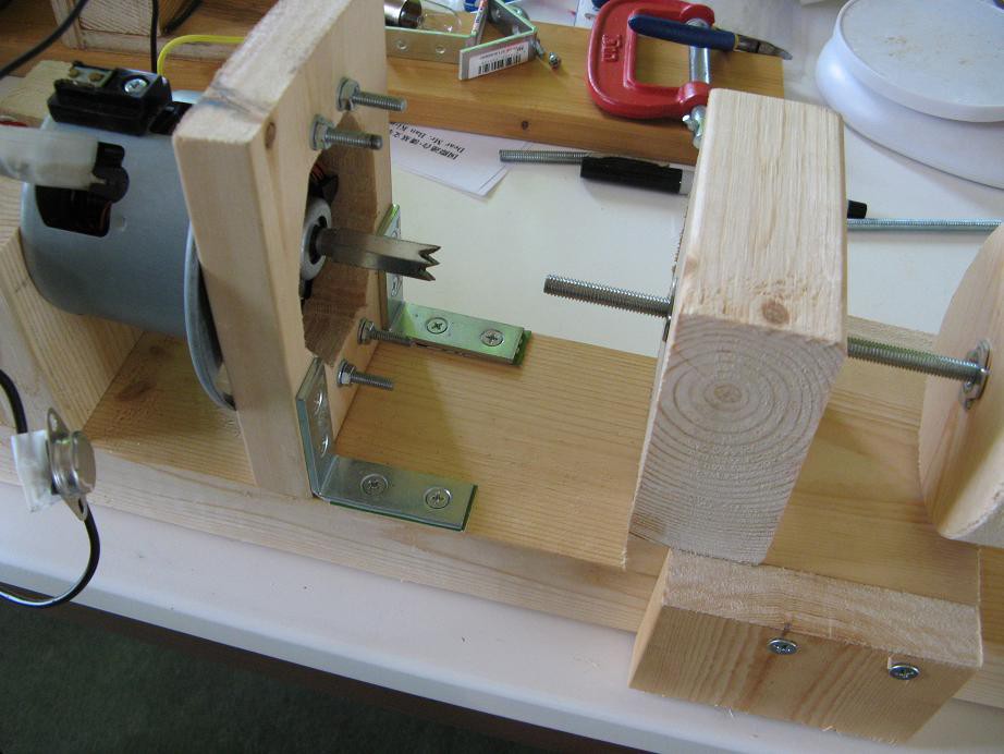
Here the two centers are facing each other.
![]()
Oh, and I sharpened the threaded rod too.
![]()
Next, I finally made a control panel out of a plastic cutting board that I had left over from the stargate project. It just has a power switch, rotary encoder knob and a display. I was thinking of putting start and stop buttons on there too, but haven't gotten my hands on any good buttons for the job. At this point I can just use the knob and start out at 0 rpm. The power switch is my quick shut off.
![]()
Here is the back side of the control panel. Notice that the knob is still attached to a chunk of pcb from the stereo I pulled it out of. Everything is held together with hot glue.
![]()
-
Rough assembly and some tests
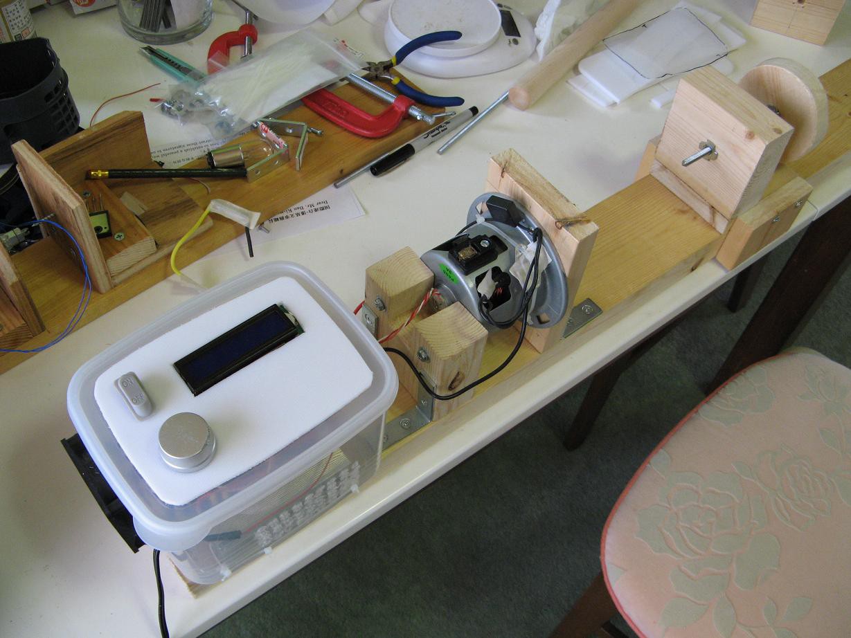
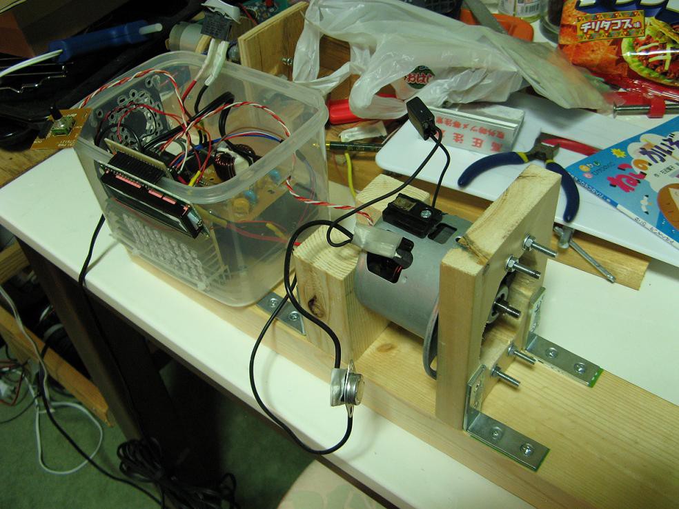
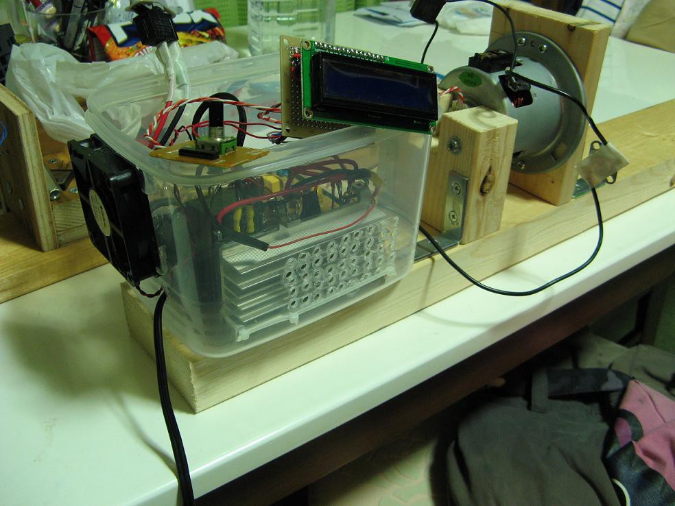
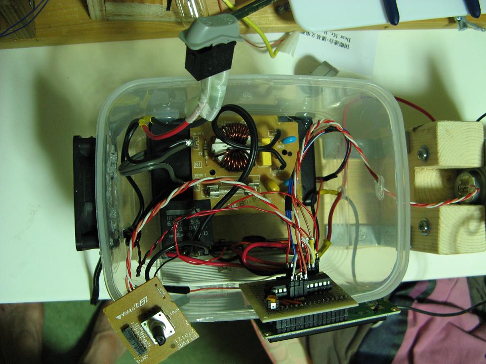
07/24/2014 at 13:43 • 0 commentsThe motor is now attached to a 2x4 using some wood blocks and L brackets as you can see in the pictures. It feels really solid. Right behind the motor is the control box, which is a plastic food container from the 100 yen store. It is still far from complete, but functional. It will eventually have a control panel on the top, but at this point the controls and display are just hanging over the edge.
![]()
![]()
![]()
As for the tests, I first programmed it with some really basic debugging code and connected it to a small light bulb instead of the motor. It worked ok, but the bulb didn't seem to respond to the changes in pwm duty cycle as much as expected. Anyway, I finally got up the confidence to connect the motor and ZOOM! The IGBT failed in such a way that it was stuck on. The motor screamed like a jet engine for three seconds till I yanked the plug from the socket.
What exactly happened? I'm not sure, but some reading seems to suggest over voltage from the inductive load. I thought my flyback diodes would protect things, but maybe not. Also, the unresponsiveness to the duty cycle made me wonder if my IGBT driving was not good enough. Perhaps the gate resistance was too high to switch quickly. I was also driving it at about 2kHz, which may have been too fast considering the driving circuitry.
Try two: I replaced the IGBT with another salvaged from garbage, reduced the gate resistance, and added a 500V varistor across the motor(the IGBT is rated for 600V). Then I reduced the pwm frequency to about 240Hz. The light bulb test looked much much better, meaning that this way of driving was much more effective. Then I crossed my fingers and hooked up the motor. It worked beautifully!
Now to finish up the controls and turn this into a lathe.
Fancy lathe made from garbage
A wood lathe with closed loop speed control made from garbage
 The controller doesn't use regular PWM. Rather it switches on full 60Hz cycles. Thanks to the MOC3063 drivers this switching occurs at zero crossings. For example a half power setting would switch on every other cycle.