 Paul McClay
-
Thicker Brass bis: Made a Thing
02/20/2024 at 05:59 • 0 comments(2 Jul 2024 update: add 2nd pic)
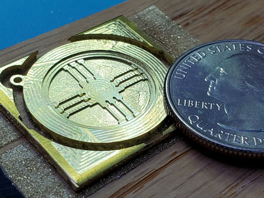
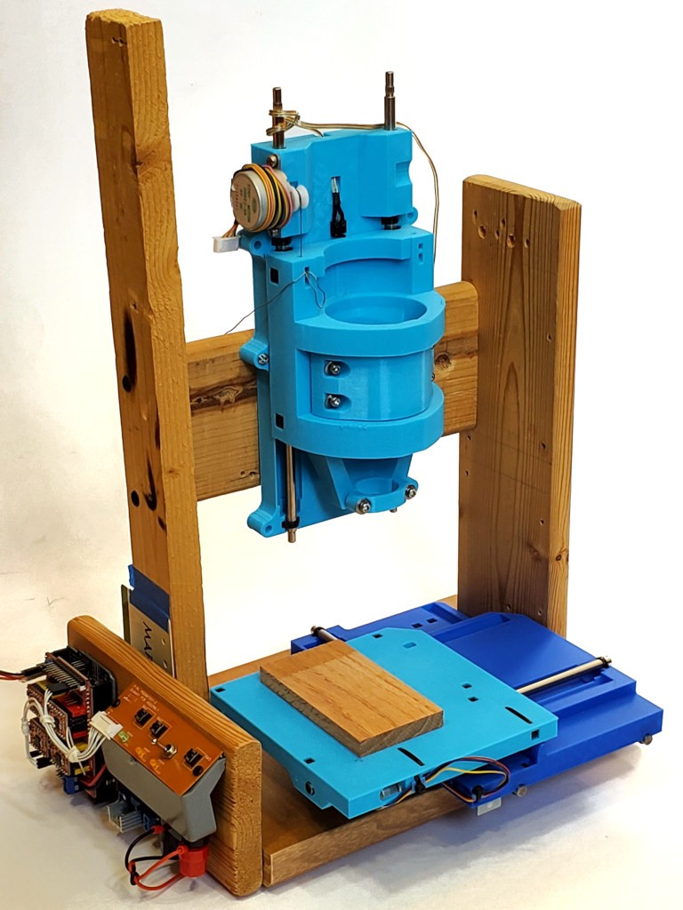
Made a thing from brass thicker than paper and that isn't just a flat cutout:
![]()
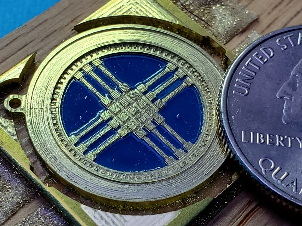
a milestone that I didn't imagine when I started messing with this toy-scale CNC stuff ⸻ <update> Tried again - better paint (more correct color and less wrinkly) but still not right
- better milling
![]()
⸻ </update> It's a shanyrak[1], as stylized in the national emblem of Kazakhstan[2][3]. Because my wife is Kazakh.
Yes, the paint wrinkled when I sprayed clear over it. A lesson in alkyd/acrylic/time issues. Call it a rough draft/proof-of-concept piece. Or maybe I should brag up my successfully executed wrinkle finish.
In October last year (writing in Feb '24), in a press to maybe possibly get a competitive HaD Prize final entry together (failed but that's a different story), I tried cutting something more interesting than a backlash test pattern in a chunk of brass thicker than a thin sheet, which failed in a confidence-inspiring way.
Months of other stuff happened.
When opportunity to try again came around, I had the idea of (re)starting with a simple figure that my wife might like -- a shanyrak -- since she tolerates all this nonsense. And Valentine's day was imminent.
That was supposed to be simple but turned into another scope creep fest... ...which could turn this into a dissertation that never gets finished so maybe I'll just add some notes to the [2] footnote in case I ever come back to write more about that.
Processroughing + lowest flats
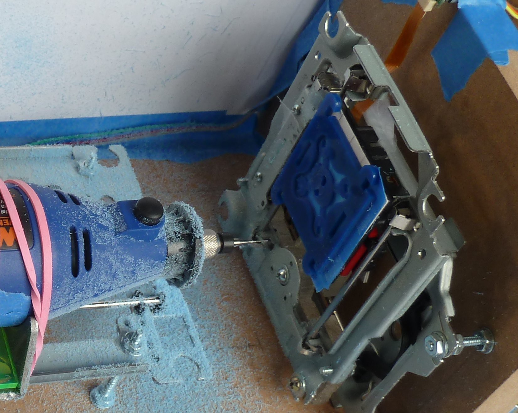
I rough cut the face, outline, and the center pocket down to a level above any detail with a 1mm end mill. Then cut the deepest pockets to final shape & depth with a 0.38 mm (0.015 in) mill.
![]()
mostly rough but finished the deepest areas I guess it doesn't take much metal to make a (relatively) big pile of glitter.
![]()
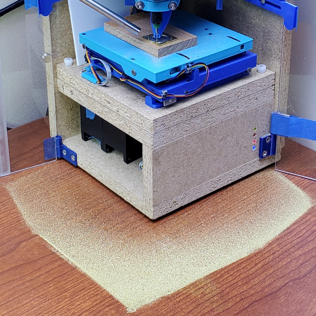
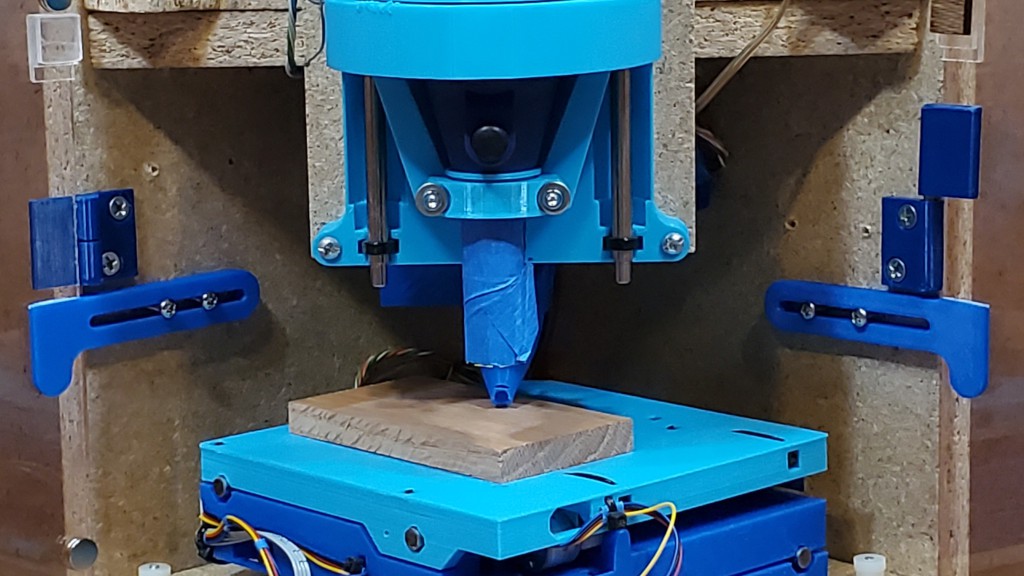
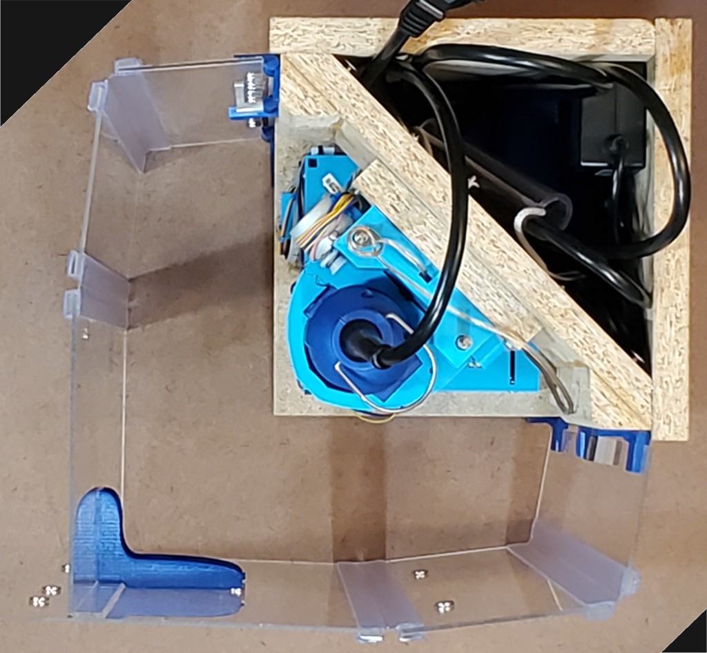
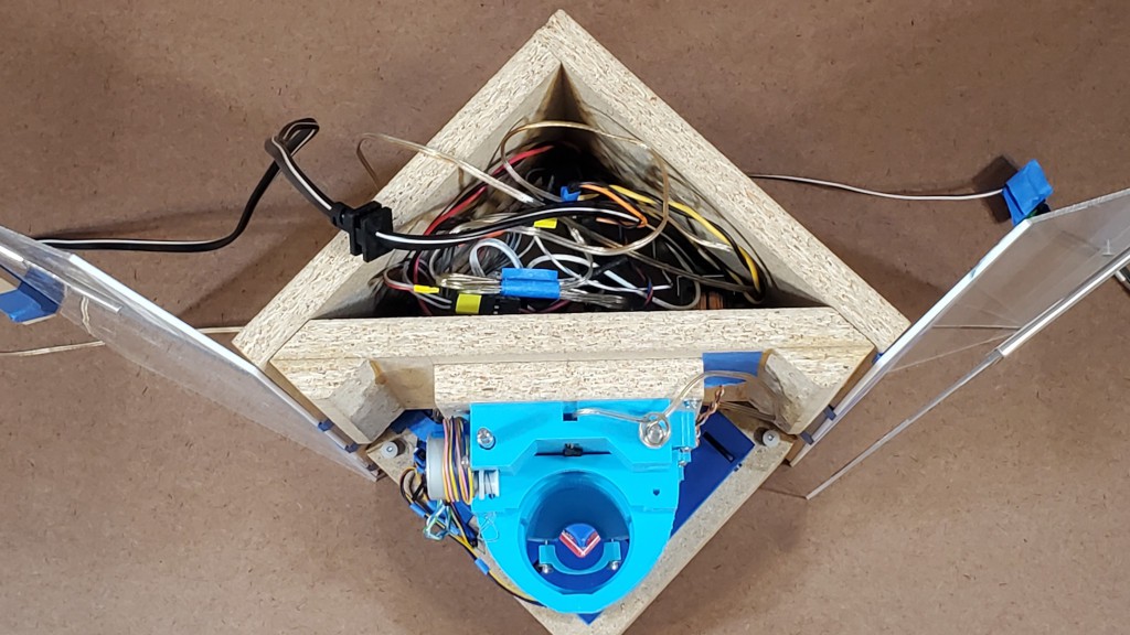
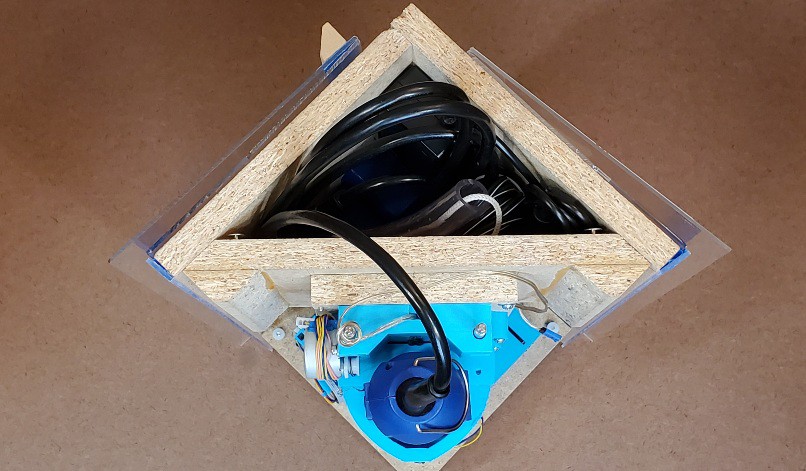
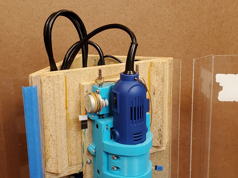
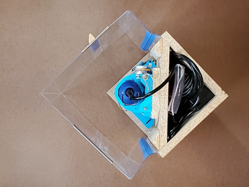
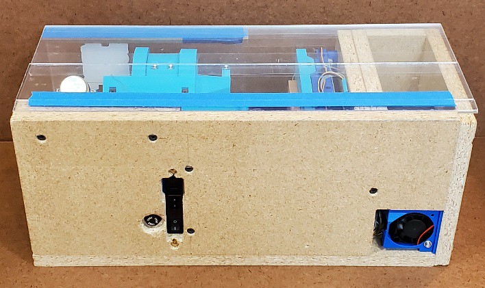
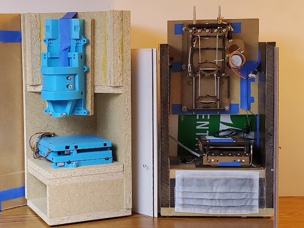
beware the glitter bomb if not caged Here's an opportunistic illustration of the divided project architecture: 1) the CNC core, whether this project here or elder sibling #Minamil 2dc: a minimal CNC mill, and 2) a structure that can be something fancy like parallel work in progress at #"Desk Accessory" CNC Milling Machine but doesn't have to be.
The CNC part doesn't care whether it's in a tidy little box or scattering chips to the winds. If you're here for the CNC you can build the CNC and carry on.
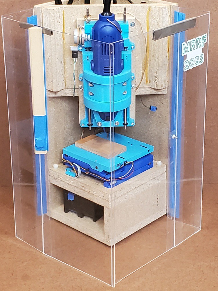
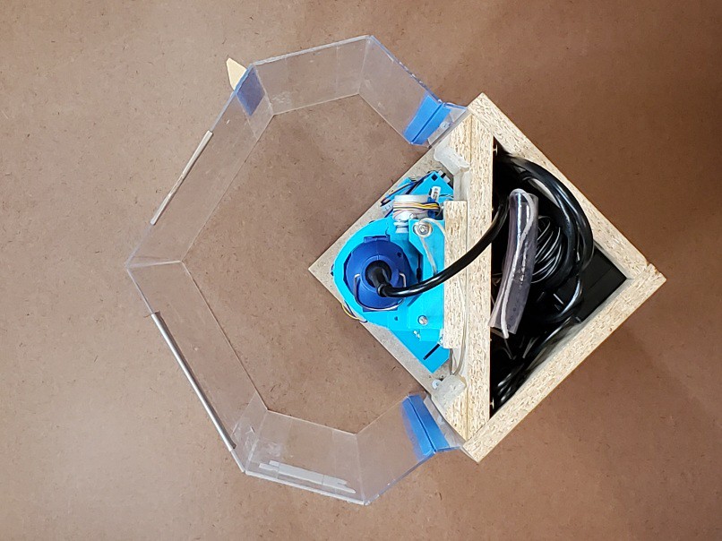
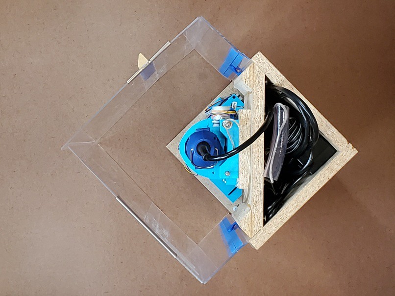
This pic shows a concrete illustration of the realized practicality of having a "desktop" CNC on my desk. The mess stayed in the box and that little patch is trivial to suck up with a hand vac. So long as it's sitting on a flat surface, which I think is a reasonable expectation for a desk.
(having written "vac" I probably should add "HEPA". and the opening in the box under the XY table is for an air filter that isn't there yet -- the double-stack fan (high static pressure) will pull air down and (filtered) out the back so fine dust doesn't float up out the open top of the enclosure. which it does. that arrangement worked pretty well in the previous frame build. that all could be replaced with a vacuum hose stuck in a hole in the same spot -- which could be interchangeable if the fan and vac hose were the same diameter. i'll have to write all this air/dust stuff in a log at some point and trade all these words for a link to that. after finishing the fan/filter box there.)
paint - and lost messages from the future
Paint's not my thing. What I learned from this encounter is to do pretty much everything differently.
I think I cleaned the surface adequately. It was freshly cut and cut dry so it should have been pretty clean after vacuuming out chiplets anyhow.
I used a rattle can, which meant masking around the workpiece and covering a fairly large area to manage overspray.
Lesson: dust again after masking & draping.
This was weird: That's probably too much paint for a first/single coat. I ended up spraying a load of paint on the thing because the paint spray wasn't landing in the narrow pockets between the bars. At all. You don't believe me. I should have taken a picture. I don't doubt that surface tension would be strong at this scale -- and such was plainly evident. But I'm pretty sure most of the atomized paint spray droplets were smaller than the width of those pockets so some spray should have hit the bottom of the pocket before encountering any other paint to interact with. I've seen closely spaced fresh cut edges attract debris (can't really call that "chips") in plastic. Could something like charge concentration on the cut edges here have repelled paint droplets? Or attracted paint to the raised surfaces so it didn't get to the pockets (but the tops of the bars didn't attract a lot of paint -- maybe most of what landed there got drawn off the ends of the tops of the bars by surface tension)? In the earlier event, touching the plastic edges killed the attractive effect. In this case I'd touched the cut edges plenty -- tho carefully not with my fingers and perhaps not with anything conductive. But brass is decidedly not dielectric so how would any local concentration of charge happen/persist? Maybe if the piece as a whole were charged up, sitting on wood, then maybe sharp edges would concentrate field effects? Maybe I'll be embarrassed when someone points out the obvious answer that doesn't require any mysterious foo force? Anyhow, I just piled up more paint on there until adjacent paint piles (piling up because surface tension) amalgamated and wetted the surfaces that were no longer not under paint.
![]()
Next time I can remember to dust again after masking and draping -- or I can just paint with a paint brush. And let the selective spray mystery remain a mystery.
That's Rusto-Oleum "All-Surface" paint. I thought it might stand a better chance of sticking to bare brass than some random hobby acrylic paint that I have (that would be a more nearly correct color). I didn't bother to consider compatibility between this stuff and the clear that I wanted to spray over it to keep the brass shiny. And it's not a great color; the blue is supposed to be sky. Because a bona fide Şañyraq will be overhead. So, yeah, wrong paint.
unpaint - and details
The idea behind leaving a little thickness of metal over surfaces that weren't supposed to be painted was that all the paint that wasn't supposed be there wouldn't be there anymore after milling from roughed surfaces down to finished details.
![]()
mechanical paint stripper ![]()
milling done
clean up - clear over - and lose the chemistry bet
I did a little manual cleanup under magnification, polished the two circular rims which are the highest features on the face, washed it with TSP (because teh Internet said to) and sprayed it with a gloss clear acrylic blue-paint-wrinkling agent to (maybe) keep the metal shiny. Here's the first pic again to show that ended up looking like:
![]()
She likes it. Yay.
I've got some ideas for maybe getting a cleaner product straight off the machine next time.
[1] but IMO that's an unhelpful rendering. You're reading this in English so call it "shangrak". Or "shangarak" if you really want to account for all the letters, but then at least half-swallow the middle a. My guess is that whoever decided to render Шаңырақ (latterly Şañyraq) as "shanyrak" knew mainly Russian (i.e. Muscovian) or other non-Kazakh Cyrillic script language because they got Ш-to-sh but missed ң-to-ng, suggesting they couldn't be bothered to distinguish ң from н. Bah.
[2] which seems to be almost-but-not-quite standardized - which complicates modeling it :-/
- a drawing - with some helpful numbers; at arms length looks like it's supposed to be a reference, but it's not great and I haven't found any instance that matches; and not flat (there's one in a cabinet somewhere that looks pretty flat)
- a high profile example - said to be quite large for the room tho pic doesn't really show scale, so it's meant to be in close in front of lots of eyeballs -- but it's just not very well made
- money - I figured if anyone would aim for "official" proportions it would be the keepers of the currency -- but they kinda punted the Şañyraq details
- architectural - IMO this looks like the cleanest rendition I've found, but it's awfully dirty :-/
- big early instance - b/w photo at top. was that the definitive artifact? where is it now?
[3] "Qazaqstan" in proposed (re)adoption of latin script
-
Build? Start here.
02/06/2024 at 05:39 • 0 comments(15 Oct 2024 update: Discord getting traction; less old "less simple" frame image)
![]()
the this bone's connected to the that bone
I've tried to make the CNC part of this (relatively) easy to reproduce from some 3d printed parts and a minimum of other stuff. It should go together by assembly with as near to zero fabrication as possible.
Writing up how to actually get that done is a project in itself. What I have so far is pretty rough, but I think it conveys enough information to give you a fighting chance to build a working machine. As of writing, I intend for this log entry to serve as a stable "start here" point with links to the latest work in progress as it evolves.
Please let me know If you're thinking about actually building one of these. I've set up a Discord server. which has gained some traction as the place to plug in if you want to build one of these for yourself for real. (I've also enabled "public chat" for this project (big orange button on the project page, or right here) and you're welcome to check in there if it suits you better, but, as of mid-October 2024, you'll find it pretty quiet in there.)
Here's what I've got so far...
---------- more ----------
CNC core
To make the functional CNC core:
(If you prefer laser cutting over printing parts, check out the "2d cut parts" flavor of this idea: #Minamil 2dc: a minimal CNC mill.)
Frame
Then you'll need a frame of some sort, for which I don't have detailed plans but leave that open for artistic interpretation. That could be
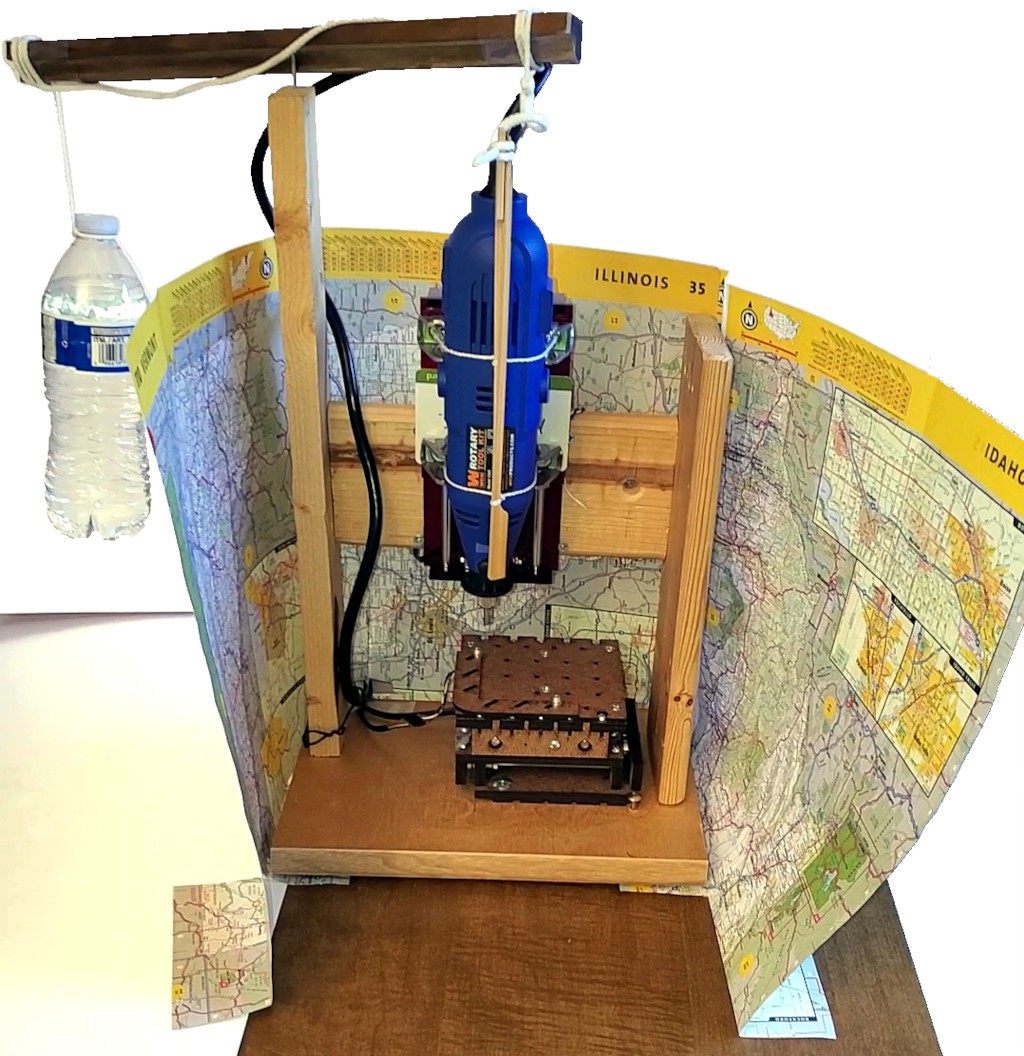
very simple
like this:
![]()
scraps, screws, and an eyeball or
less simple
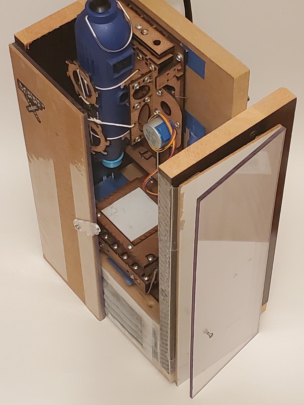
like this (also work in progress) which is the subject of #"Desk Accessory" CNC Milling Machine
![]()
all the feature creep -
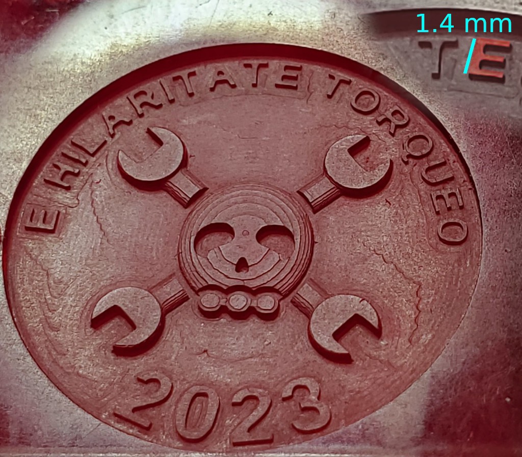
Jolly Wrencher 2023
01/01/2024 at 05:57 • 0 comments![]()
Cut but didn't publish this back in October, so I better hustle it up here before 2023 expires (in my timezone)...
---------- more ----------The circular field is 21 mm diameter (smaller than a $0.25 coin) and the lettering around the upper arc is less than 1.4 mm "high" (typographically vs Z axis).
Rough cut with a 0.5 mm (0.020 in) end mill, then detailed with a 0.025 mm (0.010 in) mill.
![]()
-
Thicker Brass
10/10/2023 at 00:26 • 0 comments![]()
Brass. More than 5 mil thick.
If you squint, you might see a Jolly Wrencher in there. It didn't come out like I wanted, but the fault was mine.
---------- more ----------After changing from 0.020 in (0.5 mm) end mill down to 0.010 in (0.25 mm) for details I set Z too low (because reasons + failed attempt to adapt) so the tiny mill cut a lot more than intended, right up until it crashed in the last 0.001% of the cut, proving that it absolutely can do the job. So I'm fairly confident that the next try will go better.
...reflecty...
![]()
-
doors again: current and (maybe) future
10/08/2023 at 05:20 • 0 commentsIn the previous log page I walked through the history of the enclosure part of "frame+enclosure". This entry describes the latest iteration. It's all kinda deep weeds and I don't know if anyone will ever actually read it. I wrote a lot about this because it's been one of the more convoluted parts of working out something that might work well enough to call "done" for this project.
Many words and little proofreading follow, so I have no idea how this all differs from what I think I wrote...
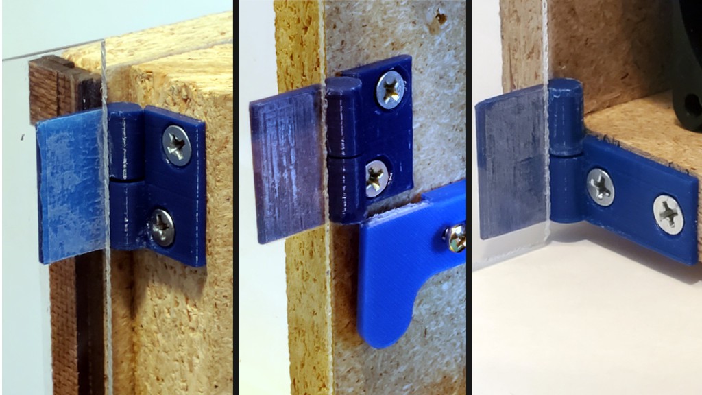
In all previous flavors of storage/working enclosure, the doors fold 180° to collapse for storage, then close rather conventionally like doors. Another possibility was to have each door fold 90 deg then each door closes around the two open sides, one over the other. That would avoid having two edges meet at a corner -- which seemed like trouble before discovering that it worked quite well. Reasons I didn't do that in the first place included the hassle of making the hinges different between the two sides, and more significantly, with single-thickness door panels, that leaves no opportunity to attach anything to the inside of the outside door, I already wanted to avoid attaching anything to the outside. So that was going to complicate closure.
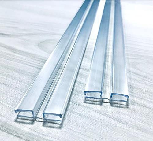
Then I looked for hinge options to get away from tape and decided to try these:
![]()
seller's pic They multiply the panel thickness. Folding them double also adds the width of the web between the two panels, so the fold would be that much more than twice as thick. Quite counter to my earlier obsession with minimizing footprint @@@link.
That was a reason to reconsider wrapping the doors around the corner instead of folding double. Joining thin panels with thick hinges also relieved the problem being unable to attach anything to the inside of the outer door or outside of inner door (i.e. only to inside of inner door). So, giving that a try...
![]()
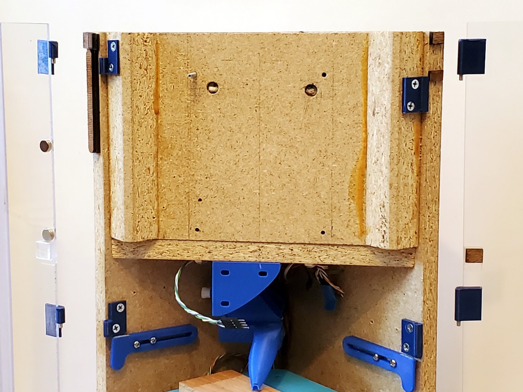
Those hinges fit between panels. Their thickness sets a "free" thickness for hinges at the frame. After looking at a lot of unsuitable hinges, I figured out that was enough to space for bespoke hinges.
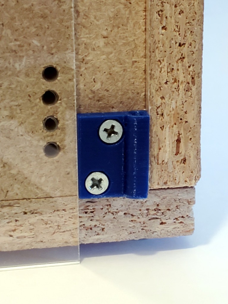
![]()
The dark material in that pic is just tacked on to show where the solid side would end if it were cut for the thicker panels. The outside door edge should bear directly against the solid side panel.
"bespoke hinge" really means three different hinges -- just for that side.
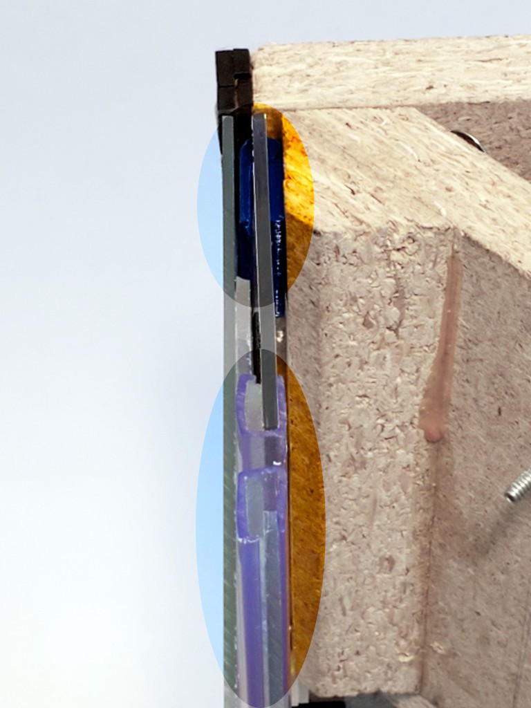
![]()
On this side the hinges carry the inner door while the edge of the outer door should bear directly against the inside face of the solid side panel. For the inner door, the hinges also back up against the solid side panel, and clearance between the fixed half and the edge of the door goes to zero with the door closed. When pushed in from the corner, the inner door should bear directly against the fixed parts of the hinges which bear against the solid side panels. A few small plastic parts will be more squishable than the whole door edge meeting the side panel, but the hinge in the inner door will buckle and/or compress before sending much load into that door panel anyhow.
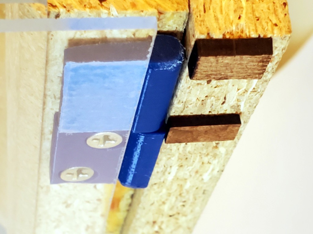
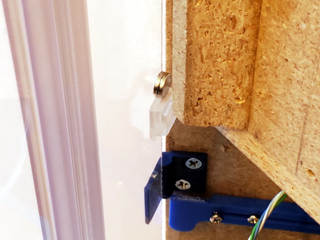
Then there are more different hinges on the other side to keep the hinges behind the plane of the outer panel.
![]()
Again for the hinged panel the clearance between the moving panel and fixed half of the hinge goes to zero with the door closed, to bear whatever load they get which will be moderated by the hinge between door panels on that side.
In that corner, the inner door panel bears against the thicker fixed parts of the hinges, which again bear against the frame side panel.
(This pic also shows how the enclosure panels extend below the hard box to the level of the bumper feet to sweep the work surface. That helps to contain the mess. And I think flat-ish smooth-ish surface is a reasonable requirement for what to have under this thing.)
![]()
That all adds a lot of bulk, especially where the folding hinges double up at the corner, kills the "snagless" smooth sides. At least the corner hinges keep flush.
![]()
Again the dark stuff at the frame corners shows what should be the extent of the solid side panels if that were cut with those hinges in mind.
Magnets hold the outer door panel inward to what would be flush with or just behind what would be the edge of a matching frame. That gives the edge of that panel some protection from getting knocked open.
Lots of magnets because the magnets aren't used very efficiently in this first try. On the left they are separated by the door panel thickness so they attract weakly. Doubling the inside magnet helps. However, the magnets won't much resist the panel sliding sideways instead of pulling away, and the great big hinge sticking out of the opposite corner wants to snag any passing hazard and pull the panel away sideways. Another set of magnets around the corner help resist that because they would have to be pulled straight apart instead of sliding. On the right the magnets get closer but still don't meet unless one side is doubled. While the photo shows only one set of each, there are more sets spread along each corner. So, lots of magnets. Not a big deal, but the number could be reduced by using them more effectively. I got magnets that are a little thinner than the door panels, so they could fit into a hole through the panel which would solve the separation on the left, some spacers could solve spacing and planar orientation on the right. Cup magnets and striker plates would hold more with fewer magnets. But just using lots of magnets is simple for now.
As a consolation prize for letting the doors get thick & snaggy, hinges made to suit solve the awkward door problem decisively.
![]()
And these projecting blocks secure the doors in place in blocking them from lifting up when closed.
![]()
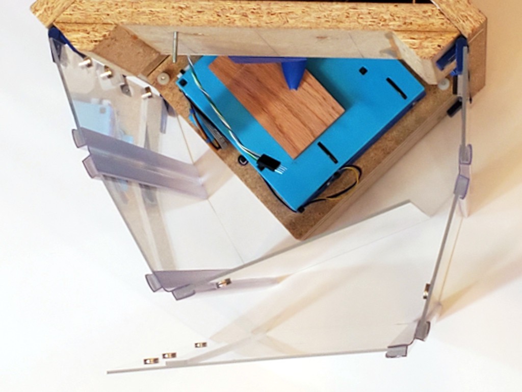
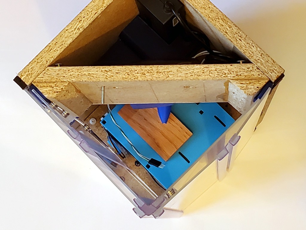
The flex hinges are pretty stiff, so the enclosure wants to be a couple of arcs instead of a square. Besides looking inelegant, they threaten to encroach the clearance required for the X+Y stage to move around.
![]()
That kind of a variation on the "fourth panel" problem described earlier. So I dug up and adapted the slide-out side guards made for abandoned intent to shrink the frame footprint to help keep the enclosure panels adjacent to the frame out of way.
![]()
Then squaring the corner where to two sides of the enclosure meet helps to force the first flexures near the frame into a sharper angle and straighten the second flexures closer to flat to make the box.
![]()
The blue thing in the corner is attached to the left side and attaches to magnets on the front panel to lever the corner close enough to square. Since it's attached to the inner face of the inner panel when closed, it can be big and fit in free space inside the closed-up box. It's also too long. I had a shorter dimension in mind, then second-guessed myself by imagining a problem while doing CAD away from the physical object to look at. Meh.
But, hey, even if I'm not thrilled with all of it, that's the first enclosure for this thing that hits some main points:
- closes when closed (storage)
- closes when open (work)
- not awkward to work on (doors removable in this case)
- not made of packing tape
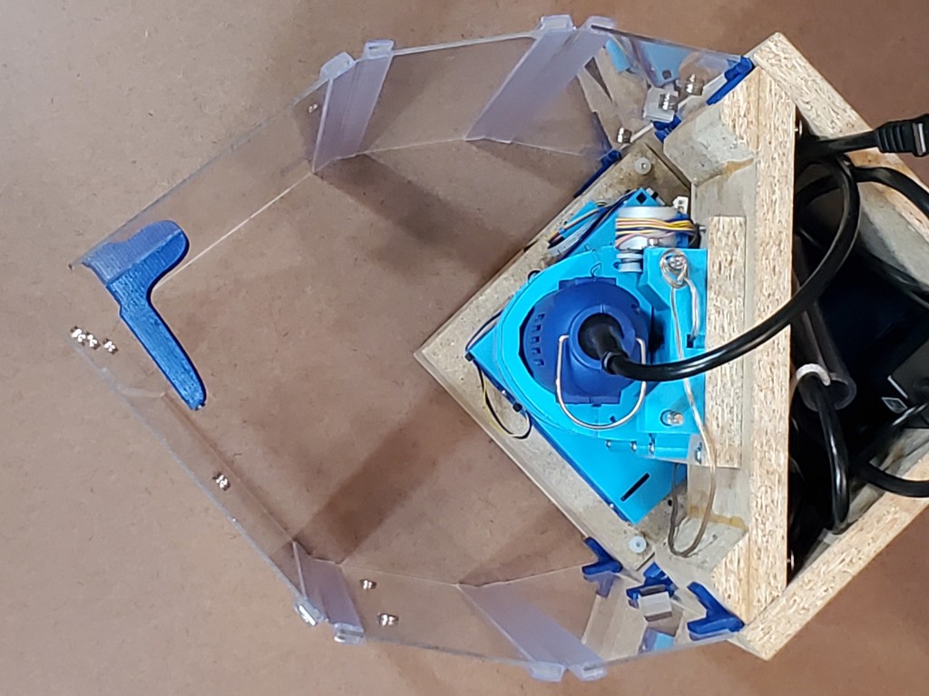
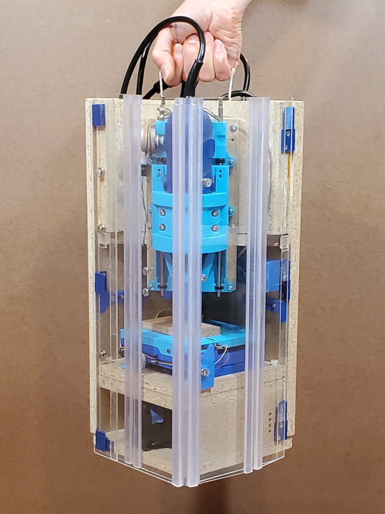
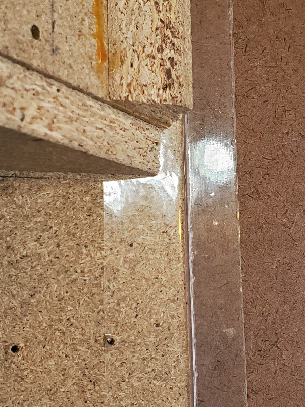
And it has a convenient carry handle. It's more comfortable than it looks but the comfy part is clear and just fits in my hand so the corner you can see is hard to see.
![]()
Future?
I've already whinged about the thickness of these flex hinges. While these clip on the edges and add some to both sides of the joined panels, I"ve also found some that bond to one side. But they all add a lot of thickness. Some were kinda flat-ish, but none were flat. Meh.
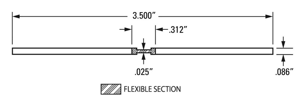
Recently, and long since ordering the flex hinges used here, I found some actually flat acrylic+"polyester thermoplastic hinge membrane" co-extruded flexures about the same thickness as the material i used here. Check this loveliness:
![]()
From Petro Extrusion Technologies, Inc. "DR" is a flavor of acrylic (TIL). And I've read that essentially perfect butt joints can be made between acrylic sheets. I don't know if that will be practical undertaking for me for this project, but it sure sounds like the closest thing I've found. The edge of a 180° fold will be more squishy than the earlier iterations with tape hinges, so maybe it wouldn't directly replicate this level of abusability...
![]()
... or maybe the flexy bit is tough enough to take that and add a little compliance to moderate shock. ?.
Or maybe UV resistant packing tape is the easy answer. ?.
-
feature creep vol. {n+=1}: doors
10/07/2023 at 05:34 • 0 commentsAnother log mostly about already-dead stuff that I took pictures of before breaking it down to make it different again.
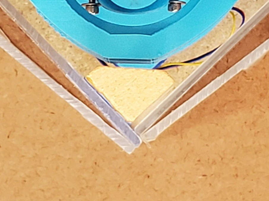
I tried to make this vulnerable corner at least not super fragile. It turned out to be super not fragile.
![]()
It will take a much harder hit without damage. But the under-developed closure is just a short peg that sort of gets close enough to a small magnet to be weakly encouraged to not wander away, and hitting it much harder was bouncing the doors open, and that would confound the point of this visual demonstration. So just a tap for show.
I think I'm going to miss that clean, durable arrangement. The problem is that it was hinged with packing tape and that's not a long-term solution. I've been noodling ideas for making hinges that should age better with least loss of compactness or acute durability.
I've had another go at it, and maybe found a thing to try next. But first, a little about how we got here.
Starting with some history from the preceding laser-cut designs up to what I liked about the last iteration before breaking it.
Before beginning
Way back in pre-history, a piece of paper on each side of the frame did the job.
![]()
CDROM discards are a perilous gateway drug.
One thing lead to another and I got started into the laser-cut precursor to this project, retronamed "Minamil 2dc".
Zeroth: zeroA couple of 2-axis test ⋅ cuts with just the first XY table encouraged me to:
- keep going with the idea
- rig up some sort of debris containment ...
First: pepakura
... so before cutting anything, the first 3-axis frame had a 3+-sided paper shroud.
![]()
The "wings" projecting forward from the sides kept debris pretty well corralled to the tabletop. That actually got a little bit elaborate where it folded around and projected beyond the frame, and passed moving wires through without opening a big hole. (cable management has been a thing from the get go)
Aside: in this project I emphasize the distinction between the CNC mechanics and the fancy enclosure that you don't need to make the CNC part work. Here illustrated. You don't even need a road atlas if you don't mind a little mess.
Made from garbage-grade wood scraps, used uncut as found.
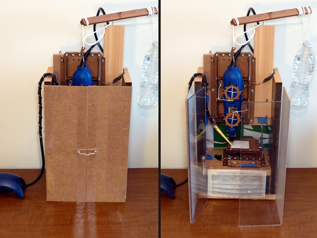
Second: win
This actually works really well.
![]()
Four-sided enclosure. That really helped to make table-top work more simply practical. Taking advantage of how the horizontal axes collapse to a footprint smaller than needed in operation, the walls of the debris corral fold in to make a smaller box that doesn't have to occupy a bunch of space that it's not using.
Having the front panels cut before I had any idea what to use for hinges, I just taped the panels together to visualize the basic idea while I figured out what to do for hinges. That worked well enough to become the answer for hinges.
Aside: the side panels were cut tall enough to be taller than the raised Z axis (sans tool) and protect it for mindless storage. Then the Z axis got longer and broke that feature. The counterweight and its mast and beam fit inside[a] the closed box for storage -- until the counterweight got killed off.
[a] Sub-aside: that vid emphasized need to have a vacuum handy. That was self-inflicted by opening the doors outward then getting clingy debris up to my elbows after reaching in there. Later I got the clue that pushing the doors in, like the one on the left in the right half of the pic above, allows reaching in and doing stuff with much less hassle.
Made from less crappy wood, HDF, and acrylic scraps, cut on a table saw.
A relevant feature of this version is that the attached doors fold back flat against the side panels.
![]()
That proved really helpful when flipping the box around to do stuff with the doors open, and when handling a removed side panel without either removing then re-taping the door panels, or dealing with an awkward big thing that's either awkwardly floppy or awkwardly levering excess load on hinges that aren't supposed hinge that way.
Then: another
I accidentally made another frame as a side-effect of working up a 3d-printed adaptation of the laser-cut machine -- which turned out different enough to become a new (this) project. Oops.
![]() Still didn't know what to do with the door panels. Here tacked on with some blue tape:
Still didn't know what to do with the door panels. Here tacked on with some blue tape:![]()
That was worse than it looks because the tape strips on the inside are too close together in the middle to constrain the panels from twisting away from the outside-only strips at the top and bottom. Meh.
When I cut parts for that frame, I still hadn't really figured out what to do with the door panels. I already knew that the ability to wrap the doors around flat to the outside of the frame was useful. Also I wanted to move the hinges in from the extreme corners of the frame for durability. I didn't find a great way to have both so I gave up the fold-flat idea figuring that at some point I -- or anyone replicating the idea -- would be mostly done flopping the thing or its parts around to work on stuff.
I wrote up tearing down that iteration of this enclosure earlier -- and said little about the door panels because they weren't much improved over the gif above.
![]()
Indeed awkward. You couldn't even lay the thing down on either of its solid sides without one door doubling the surface area and the other door stuck off in space prying its hinge apart. Awkwardness and feeble hinges combined poorly.
Otherwise, that was working well enough to think of taking it to MRRF -- but with the doors done differently!
Fourth: fourth
The next idea was adding a fourth panel, and so a third joint, to each of the three-panel doors.
![]()
Just a little board-thickness strip, more "hinge" than "door".
![]()
In addition to allowing the doors to fold around, this also helped with better attachment. It wasn't done already because I had to disassemble the frame to tape the inside faces. That made the attachment semi-permanent. Making the awkward thing -- each side panel separately and the whole assembly together -- permanent wasn't attractive.
No such problem taping up the little stub panels. They could harmlessly become permanent(ish) appendages of the side panels. In fact, they're still there now because I left them as an undo option in case the next thing didn't work out.
![]()
That made it relatively simple to attach or remove the doors. I started with blue tape for simples, and that worked well enough for the duration. It would have been trivial to upgrade the tape if I thought I was done messing with that for a while. The blue tape re-sticks well to acrylic and I used the same four strips throughout. "Better" tape probably would have been a consumable at six feet per detach/reattach cycle.
![]()
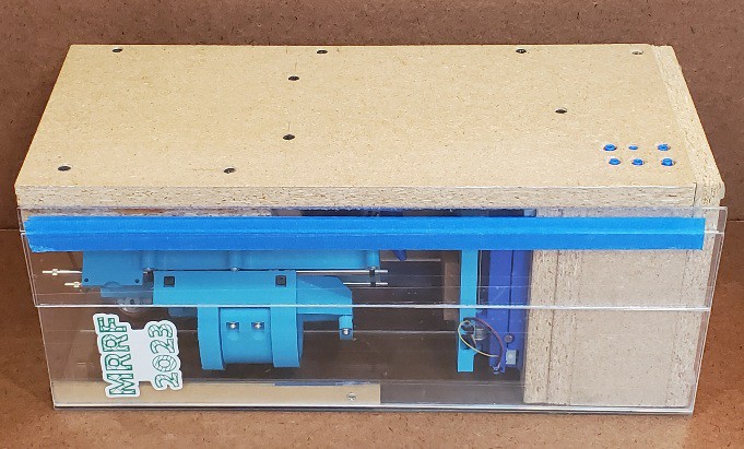
So these were the doors that went to MRRF.
![]()
The metal clips on the tops of the doors were an interim fix for this problem:
![]()
(that wasn't necessarily bad but it was too easy for the unconstrained doors to collapse back into interference with the horizontal axes)
Like so:
![]()
I didn't like the loose (i.e. lost) parts but had a couple of ideas for solving that:
- (preferred) closure that forced the door edges to meet at a right angle, or
- (fall-back) pin-in-slot retainer for sliding clips; the front (bottom above) clips slides easily between working and storage positions and the left (top above) clip could be un-hindered to do the same)
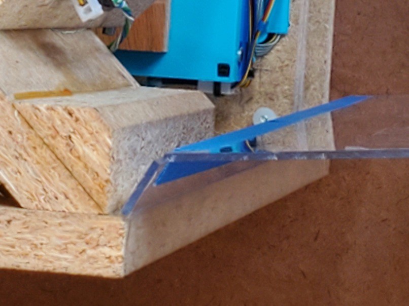
I also added a couple of slide-out retainers to flatten back the stub panels like so (look close...):
![]()
But those were really a superfluous left-over from abandoned aspiration to shrink the footprint by moving the X+Y stage back into the corner where the axes could hit the un-flat door panels. (but we'll see them again...)
As mentioned up near the top of this log entry, the storage-closed closure was weak with just a little magnet weakly attracting a little peg (screw). But I like that the doors were content to stay closed and from the outside (laterally not above/below) nothing could get behind the doors to push them open.
The doors, each folded double on one side, met at a "T" in the corner.
![]()
The peg-in-hole closure positively retained the left side against any oblique contact (from the right in the photo), it the positively retained left side protected the magnetically retained front from any oblique contact.
In addition to not adding any bulk, the "weak" tape hinges contributed to the strength of the closed box by their being invulnerable to compression.
The overlapped front door positively supported the overlapping left side against inward pressure. The front was less positively supported by the corner piece attached to the left side, but any rigid flat thing pressing against the front would bear on the edge of the left door instead of pushing back the front door. As a benefit of moving the hinges in from the corners, the other edges of the solid panel in each folded door bear directly against the insides of the solid frame panels.
From all that comes the bashability demonstrated at the top of the page. The solid panels in the folded doors won't yield until they buckle.
A bit part of gaining durability from resistance to compression comes from avoiding anything but simple compression against edges by keeping the four sides entirely flat (depressions allowed but not projections).
![]()
![]()
I mis-cut the vertical piece in the corner where the doors meet. The idea was to extend from the hard deck up to ~exactly the plane of the top of the frame, which the doors should be slightly below. Done better, that would have helped make the top of the box more solidly load-bearing for things with rigid flat bottoms stacked on top of the closed-up enclosure.
![]()
My plan at the time was to replace that with a (correctly sized) sliding latch to positively lock the doors closed in addition to bearing top loads.
There's a lot that I liked about this arrangement, and I had plans (but not time at the time) to fill in the blanks. But the whole packing-tape-for-hinges idea was always a bit shaky beyond proof-of-concept. At MRRF, a couple of guys with responsible adult product development chops (naming feels too much like name-dropping in this instance) gave generous time to kick around some ideas, but we didn't come up with a clear winner that maintained all that I liked about this arrangement -- like bashability -- beyond affirming that tape wasn't really the answer. (Ever left a taped box near a window for a few years?)
But maybe UV-resistant packing tape?
Next: different
Anyhow, I looked again at more hinge ideas and found some "Clear PVC Piano Style Living Hinge" to try between the door panels. That's a big change because it gives up a lot of what I liked about all the above. But accepting a more generous minimum thickness opens up options for attaching doors to the frame. Log page coming..
-
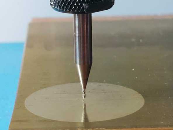
about runout
10/02/2023 at 08:18 • 0 commentstl;dr: if you can see it you can tweak it
![]()
Some examples of work from this little CNC and its precursor demonstrate pretty small runout from a generic faux-Dremel rotary tool. Repeating that will be part of replicating this project for anyone so inclined. It also seems like it could be useful to anyone trying to do fine work with a not-so-fine tool.
The point, when I get to it, will be anticlimactic. It's pretty simple. But I haven't seen it elsewhere in my limited scope of reading. So: sharing. Akshully I've written this before but that was buried in another topic and without illustration. So: sharing with pictures this time.
To reduce runout when using a cheap generic rotary tool and maybe some other small-cutter tools:
- See the current runout using stable magnification that you're not trying to hold still in your hand
- Tweak the bit toward center
- Repeat until runout sufficiently reduced
That's all <yawn/>.
More verbosely, and with pictures...
See
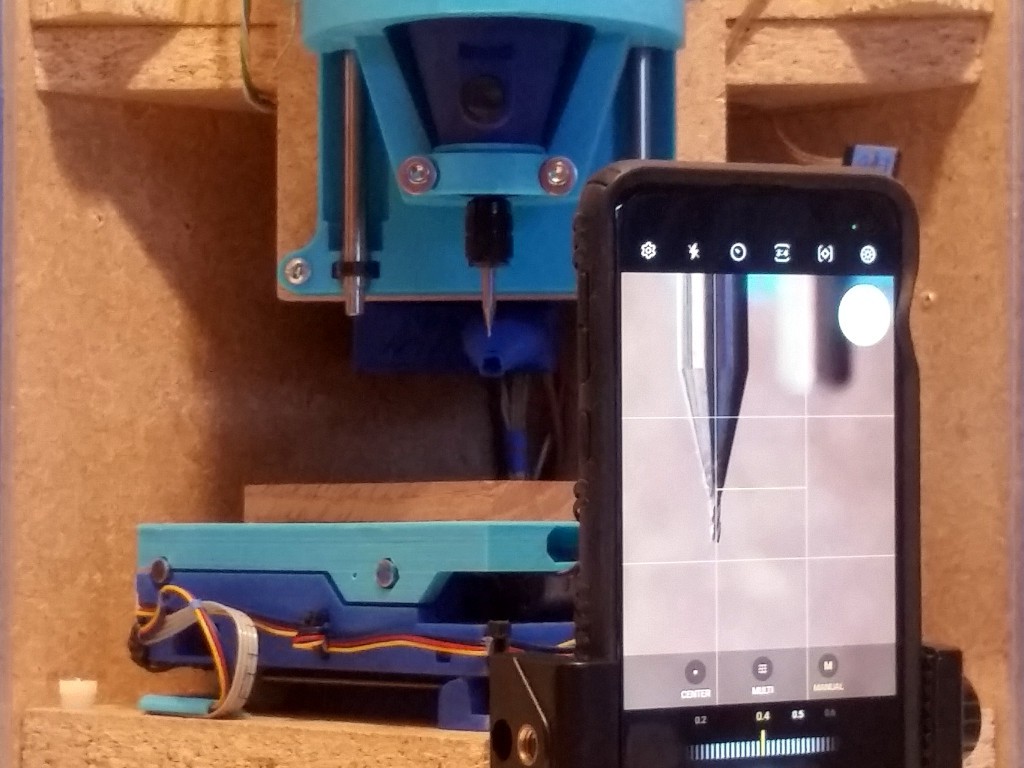
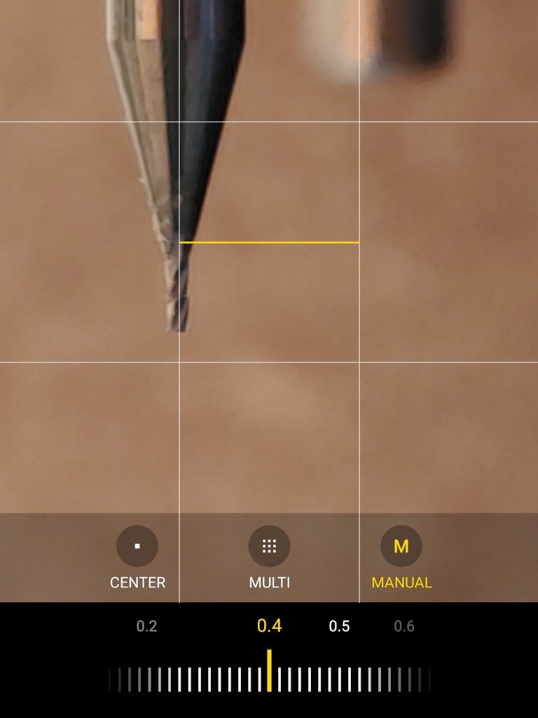
The gif above shows a view through a microscope on a stand that can look sideways. But that's cheating. Here's a method more in line with the "low cost" theme here:
![]()
That's my daily driver phone in a little pocket tripod (which I've cropped :/ but you've seen a tripod before).
- that phone is not new but not too old to have a camera that can focus close enough to do this
- manual focus in "pro" mode helps; otherwise you'll probably need to put something right behind the bit to appease the autofocus
- the viewfinder grid provides a fixed reference to help perceive small deviations at the tool tip; otherwise put something with a vertical edge close behind the tool (which might also appease the autofocus if you're stuck with that)
That looks like this:
![]()
While less crisp than the gif above, you can see that you can visually resolve a small fraction of the bit diameter (0.5 mm in this case), which is the practical scale for runout.
TweakEstablished Brand general purpose rotary tool collets aren't fantasticly precise. Generic clone rotary tool collets are really poor (typically, in 2023Q4). They are basically poorly made ball joints. The good part of that is you can point the bit any direction you want.
I'm using very small cutters here, which don't generate very large radial forces. So firmly finger tight on the collet is tight enough. A very tight collet makes it hard to make small tweaks. If the collet is not tight enough, the bit will "walk" out and drive down into the workpiece. So there's an element of "just right", but for small cutters that seems to be a pretty wide range and easy to hit.
Very small cutters break easily at the tip, so take care to apply tweaking to the shank and not the thin end.
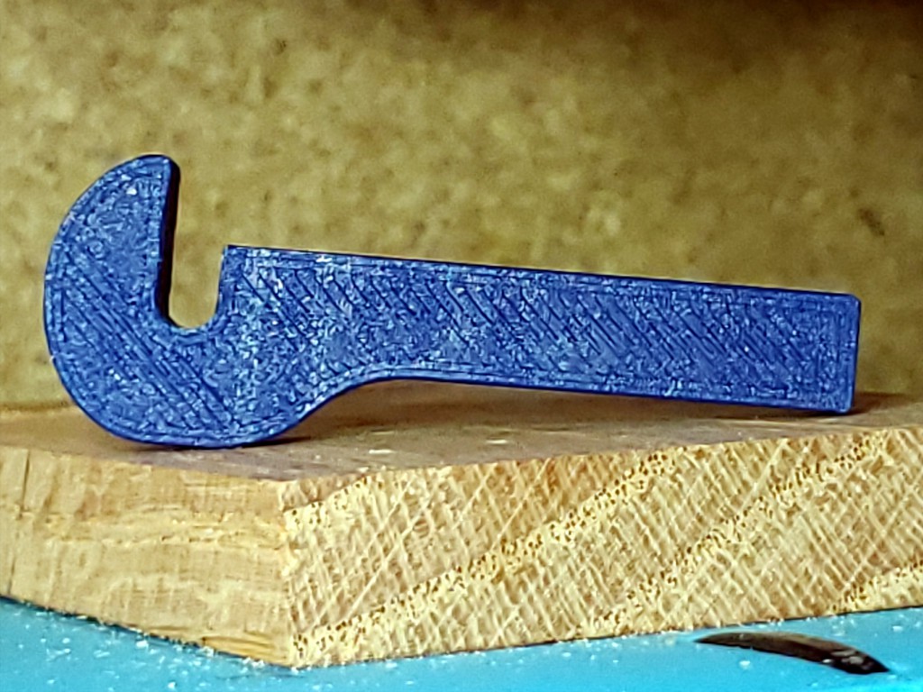
I think you should probably not do this: I started out tweaking by hand -- with a finger around the bit and thumb against the collet for good leverage. That sometimes meant pulling pretty far down the narrowing neck of a short bit and perilously close to the skinny end. Nothing bad happened, but that just seemed way too close to blood to expect that it would never go badly. So I printed a tool:
![]()
I've been using that, but It's just a first whack at the idea and not a great example. So I hope you'll make a better one.
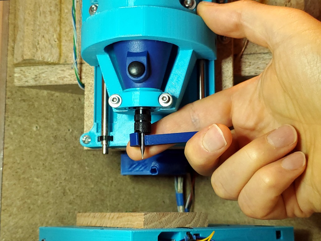
![]()
Applying tweak without slashing a finger. In the photo my finger is behind the bit for contrast, which makes this a poor example of applying tweak without slashing a finger, but you can see the idea.
Repeat
While you probably won't get as close as you want on the first try, this method seems to converge much faster than "open loop" fiddling for that once-in-many low-runout chuck-up that teases you with knowledge that it's possible but only happens when you're not trying to make it happen rant rant.
And if you're still reading...
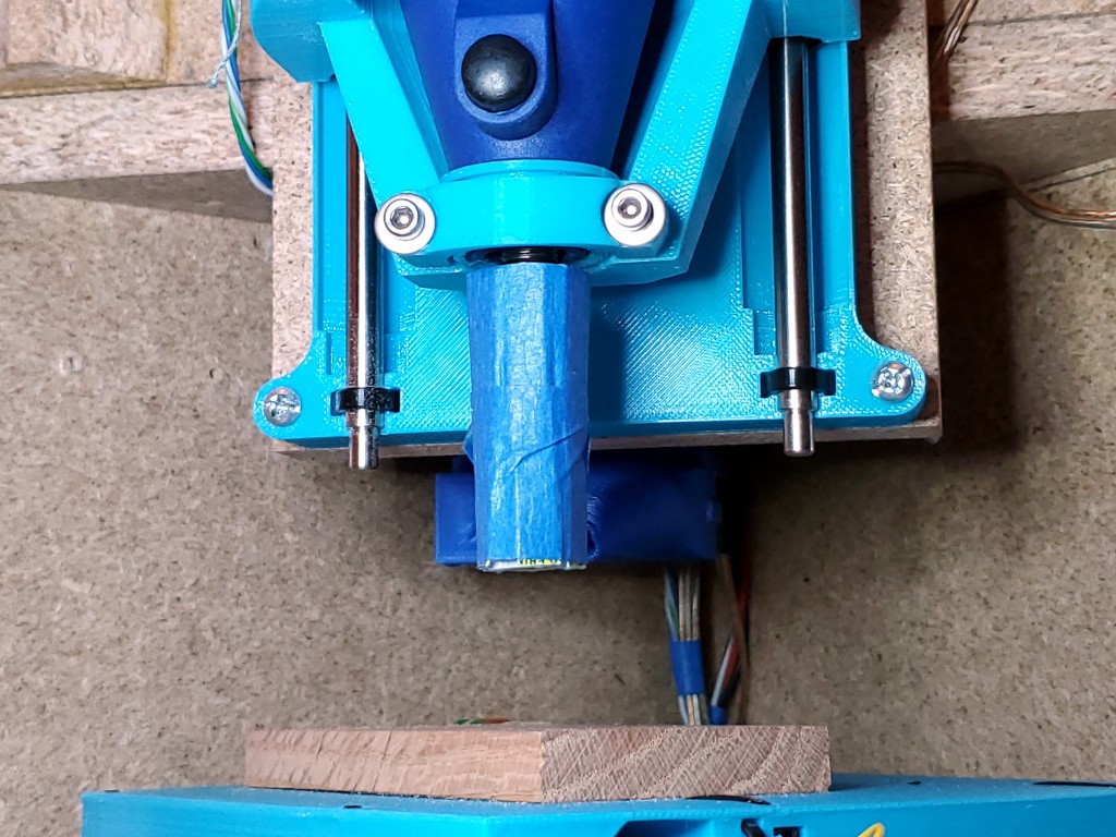
Rolling a stiff cylinder around the collet nut to make a slip-on anti-pointy guard has saved some bits and probably some blood. Especially useful when I want to leave a good set-up in the collet while not really paying attention anymore.
![]()
Coroplast (abundant free supply: election signs) flexes in one direction for easy wrapping (I probably cut some slits in one side, maybe, I think) while maintaining stiffness lengthwise.
-
to shrink, or not to shrink, that is the aggravation
09/26/2023 at 02:07 • 0 commentsThis is just a rant so I can stop thinking about it.
So I made another frame last year. The one on the left:
![]()
I made it a little big considering uncertainty about how big it needed to be.
Earlier this year, it looked like some of the packaging ideas were working and I got fired up about redoing pretty much everything less haphazardly and taking it to MRRF. Including shrinking the footprint to match shrinking uncertainty about how big it needs to be.
To start with, I cut the mounting tabs from the bottom of the X+Y stack and switched to screws up from below into the interior of the tabless bottom part. That reduced the lower bound on footprint. And also slightly confounded my first draft build doc.
But such a laundry list of things to (aspire to) do before the show, and finite time, and other life. And other aspirations on said laundry list -- mostly accomplishing or improving integrations of function into the frame and redoing the extra-janky first whack at the folding enclosure -- were bigger step changes than "see! it's a little smaller than that other one you won't ever see".
So, reluctantly, I abandoned the idea of making a new frame. That was hard to swallow because most of everything else I wanted to do would be made to fit the frame and everything made to fit the oversize frame was a nagging reminder that instead of shrinking the frame I was sinking more sunk cost into the oversize frame that I still hoped to shrink "later".
Later is now.
Cutting the simple excess while allowing for thicker hinges shaves the square from 191 mm sides to 182 mm. Not very exciting. So I've spent yet another chunk of time pouring over sketches and CAD looking at things that make the footprint bigger than the basic square dimension of the X+Y axes and what I can shuffle to debigger them. Getting down to 175 mm wouldn't be too hard. 170 mm if I do something different with the rather thick X motor connector that I've just spent time neatly securing at the back of the X+Y stack.
So I could shrink the footprint by 21 mm each side. Less than an inch but a little over 10% or a little over 20% area. That serves the objective of minimizing the footprint i.e. maximizing the brag. And I don't think any hard constraints prevent shrinking other stuff in the box to match. But then that's time spent to build a new frame, plus time to more significantly re-arrange (vs. incrementally improve) all the sunk cost other stuff in the frame.
To do, or to not do? To decide before sinking yet more time in the other integrated stuff. Aaaargh.
Ok. I'm going to not. But keep plugging with the frame in hand, with all it's surplus bigness.
BuT iT cOuLd Be SmAlLeR!
But it's not. Again. Sigh.
-
Z axis parts & assembly notes
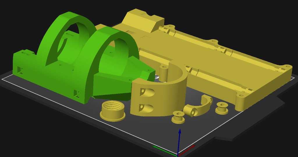
09/25/2023 at 22:21 • 0 commentsI've just uploaded STLs for the Z axis to the files section.
![]()
This Z axis works. It's also pretty crude. Unlike the X+Y stage which I've worked through several revisions, I've sliced and printed exactly one set of Z parts[a} and they've worked well enough to let me do other stuff -- like spin revisions of the X+Y parts.
[a] except pulleys; I've printed more pulleys.
If you've built the X+Y axes, then I don't think there's much in the Z axis that won't be self-evident.
The major design deficiency relative to intent is that the tool clamp is not as quick and easy to use as I'd like -- to support the idea that you can use your everyday rotary tool instead of committing a unit to semi-permanent installation.
Oh yeah - it's modeled for 6" zip ties. Almost missed that. 4" ties will probably work.
About pulleys: I'm currently using one motor and running it too hot for PLA. Consequently, I've printed a pulley in PETG. It's working fine. I don't know if it's possible to run the motor cool enough to use PLA. Because I haven't tried. If not, then more likely it's possible to use two motors and run them cool enough for PLA.
The design provides for using two motors. Mainly because the earlier laser-cut version of this basic configuration was uncomfortably vulnerable to dropping the spindle without warning so the redundant motor/pulley/cord was cheap insurance. I think that's less of an issue here because the hoist cord(s) don't pass close by sharp stuff and do run in plain sight. So you have a better chance of seeing trouble before it happens and less chance of provoking trouble. Also, by choice not necessity, I'm using Spectra® cord (UHMWPE) which seems to be practically indestructible.
Non-printable parts:
- see also here
- 2 x rods: 6 mm x ≥165 mm (length not constrained)
- 4 x bearings (3 x would work and might work fine)
- 1 or 2 x 28BYJ-48 motors with
- 5V windings
- convert to bi-polar
- 6 x m3 screws
- 4 x 20 mm (15 ≤ l ≤ 25)
- 2 x 16 mm (14 ≤ l ≤ 18)
- so could be 6 x 15 ≤ l ≤ 18 mm
- 6 x m3 washers feel like a good idea but probably don't make any real difference
- (2 or 4) x m3 x 10-15 mm screws
- string -- notes in "Hoist" part of "Step 4" in this 'ible. Or TMI.
The "nose ring" part is threaded for common Dremel-like clones and might not fit real Dremel tools. It's not essential and I don't know how much difference it really makes.
Tie motor end of hoist cord(s) and install with pulley like steps 14 & 15 here.
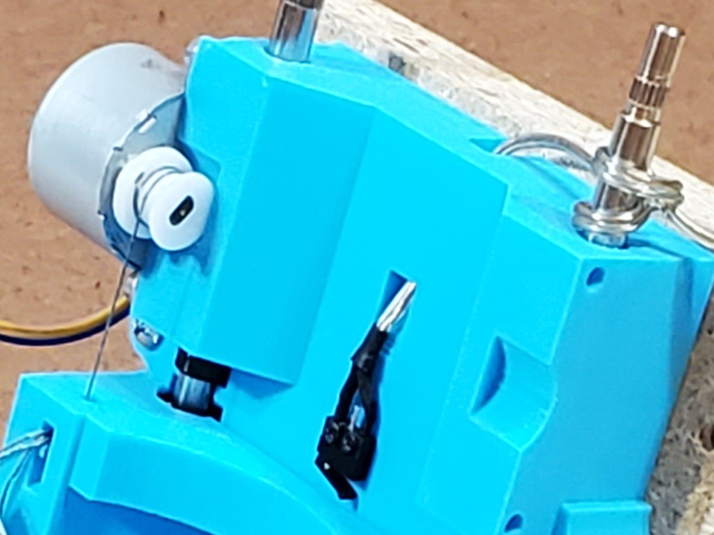
Limit switch goes here:
![]()
(the turns of hoist cord around the pulley should all be adjacent starting from the flange -- this photo was taken with the axis detached and handled randomly)
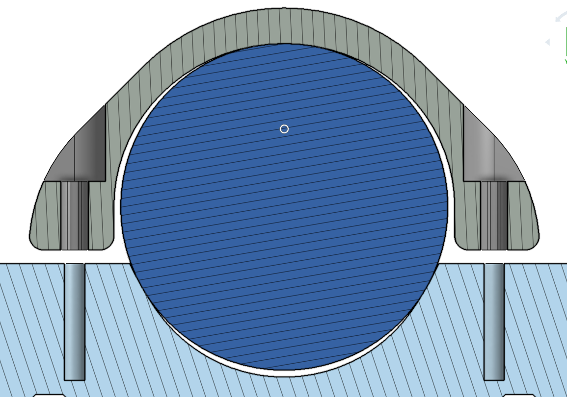
Point of interest: the clamp parts & saddles are not circular but slightly "trilobular".
![]()
Minamil 3dp: another minimal CNC mill
A very compact, very inexpensive, very DIYable, very precise little CNC mill. This one uses 3d printed parts.


 Still didn't know what to do with the door panels. Here tacked on with some blue tape: