<update today=2024Dec13: notes re grbl Z limit pin swap & limit input (not) filtering</update>
This is a draft in progress, but if you want an early start here's something to start with. There is a lot of me describing what I do rather than saying what you should do because this is just the beginning of letting daylight into the path-dependent evolution of how I've been doing this, and of the "this" that I thought I was doing. Some stuff may be mid-edit nonsense. Or pre-proofread nonsense. Public chat is open for the project -- big orange button on the project page. Also a Discord server. So far the Discord has more traffic.
Check all the V-block surfaces -- the 45º flats within zip tie circuits. See bright blue highlights in the image below. Low spots are probably ok but high spots are trouble.
Check some of the vertical flat surfaces, and probably trim some edges. See the yellow highlights in the image below. They include the inboard ends of the bearing V-blocks and both ends of bearing clearances. The outboard ends of the bearing V-blocks need to be clean enough to allow the bearings to sit level in the blocks but are not dimensionally relevant. Also the perimeter end of the motor bay and the business end of the limit switch clearance. These surfaces should be flat and perpendicular to the top or bottom of the part. but likely have some distortion due to elephant's foot, top solid layer expansion or some such, and likely need a little trimming where the vertical meets the top/bottom face of the part.
Check the bridged areas in the bottom of the middle part. They won't be as flat as other horizontal surfaces, but they should be fairly uniform. Look for strands of filament that droop a little more than their neighbors and clip those out, if any.
The length of the spaces for the stepper motor assemblies should fit the length of the motor frame "exactly", i.e. with a little squeeze, which fixes their axial positions. Any slop in that fit increases backlash. Be sure you've cleaned up the not-motor end of that space as described above (TODO chamfer that) before trying to press a motor into a tight fit, to avoid breaking out the relatively fragile thin wall at the motor end. For the Y motor in the bottom of the middle part, the bridged surface should be flat enough for the motor frame to fit flat in place without rocking over any high spot.
note: the bottom part you printed from the STLs uploaded here will have three attachment tabs around the edge that are not shown in the photos here (and fewer holes on the bottom)
"bottom" & bottom of "middle" parts shown -- check same features for "top" and top of "middle" parts
Here's what the bottom part uploaded here looks more like:
I've uploaded the tabbed version because I expect that will be more practically easy to use in pretty much all cases other than obsessing about footprint. But I wasn't really thinking about that when I started taking pictures for this draft. good V; bad V
The low locating feature at the other end of the motor bay needs to be clean too, but it always has been in my experience.
Generally clean up stuff that doesn't look right.
You can validate bearing clearance cleanup by dropping in a bearing and measuring the remaining clearance. That will be the hard limit to range of motion.
With geometrically perfect parts, that would be 77.2 mm. If I continue assembly with that part as shown, and if that's the shortest clearance of the three in that axis, I'll end up with 0.6 mm less range of motion than the CAD model. That's still comfortably more than 75 mm, which I think is ok -- 3d printed PLA after all -- and is the reason why I say ">75 mm" instead of "77.2 mm".
Check that a zip tie fits through all the tie passages. It may not always be obvious which way a tie is supposed to go, so the next couple of photos try to show orientations for all the ties in the "middle" part.
zip tie orientationsporcupine-mode for illustration only -- a single tie will suffice for checking all the passages
I think that part includes examples of all the ways ties are used in the "top" and "bottom" parts, so you can check those parts too.
"Elephant's foot" or expanded top solid layers might constrict some of the tie head openings, so check that a tie head fits freely in any that look tight, or trim edges for a free fit if needed. It's unlikely that a head won't fit at all -- that would be really bad layer spread -- but any friction holding the head will make removal a little tedious.
Where tie heads should not stick up, like on the top surface of the top part, make sure the bottom of the head clearance recess printed cleanly so that the head sits all the way down. Especially where the recess is printed upside down; sometimes a slightly droopy bridge that looks harmless enough will prevent a tie head from sitting below the surrounding surface.
drill for limit switch screws
(optional)
See the parts page for info about limit switches, screws, cables & connectors for the switches.
The tops of the bottom & middle parts have single layer recesses & shallow pilot holes that simply serve to show where to put the limit switches and screws. Shown in the second image below. There is a little extra solid fill under the shallow pilot holes to give the screws something to bite; that needs to be drilled through.
Using a drill somewhat smaller than the minor diameter of your screws, drill through the two marked locations for each switch. Or a warm paperclip will likely get the job done.
Or, if life has been too simple lately...
In the latest round of CAD update, I found a small error that I think contributed to the limit switches being fiddly in unexpected ways. So for this build (photo model here) I'm extra interested in the actual vs. nominal range of motion. So I wanted to try to be somewhat precise about locating the limit switch. So I did it like this:
In addition to a drill bit "somewhat smaller than the minor diameter" of my screws, I also picked one to match the nominal 1.2 mm diameter of the printed pilot holes.
drilling smaller than minor diameter -> mash thread into surrounding plastic
I used the ~1.2 mm bit to clean up the vaguely printed hole, and to cut a little center spot in the solid fill below. That helped with drilling the smaller through-hole in the center of the nominal locating feature.
With firm pressure for a clean start, drive a screw through each hole to form threads and make the holes easier to find blind when later installing the switches.
Re-engaging the pre-formed thread matters whenever re-installing screws in soft material. In case you didn't already know: you can do that by turning a screw slowly backward until you feel it "drop" into the thread.
Thinking: given that the screws do all the work here I can dump the rectangular depression which is vestigial.
This feels like a big nothingburger so far -- just looking & poking at printed parts. Good time to actually make ... anything? Even a little thing?
backlash adjuster lock springs
Find a couple of paperclips and make a pair of these:
Like this:
The little kick-up at the end in that pic is too tall. I think it's vestigial anyhow. Maybe reduce that to a minimal (~1 mm) turn-up at the end just enough to have a rounded end against the plastic, which will be able self-adjust position, instead of sharp end against the plastic which might ratchet the spring out of position.
Slide the bend-ends of the springs into the slots next to the drive tabs on the bottom and middle parts. The following image shows how the relief cut allows the moving arm of the spring to come away from the drive tab until the perpendicular end falls into its slot through the drive tab.
Here's another angle. The upper moving arm of the spring should allow the perpendicular end to move freely up and down in its slot.
And here's a look at the other spring installed in the "middle" part:
remove backlash adjuster lock springs
Now that you have the springs sorted, take them out and set them aside for now.
Remove a spring by lifting the 90º corner up so that the spring arm lifts up out of the narrow channel into the expanded part of the opening, then back to get the perpendicular part of its slot. "Lift" and "up" while working on upside down parts as in these photos.
Repeating this photo:
there are no springs
Believe that there are no springs in any of the following photos until they get reinstantiated in a text heading farther down.
motor prep
The two motor+screw units need some help to:
trim the projecting tab from the slider (which is why the "type A" or "type B" slider difference doesn't matter)
add a printed & tapped backlash adjuster to the leadscrew
Take care to cut only the extra tab away without taking any more material from the thin top of the slider over the internal captive nut.
Adding the backlash adjuster to the leadscrew requires [...continues...]
There are other details of that context which differ and which you can ignore because that's a different thing.
rod & bearing selection/matching
For the XY table you'll need six 120 mm rods and six bearings. If that's what you have and they're all ok, then you can skip on to the next heading.
Just ̶ ̶t̶o̶d̶a̶y̶ ̶ the day I wrote this part, a fellow HaDer reminded me that 3d printed bearings (i.e. bushings) are a thing. I think I need to look into that before I get too deep into writing this section.
In my experience of buying from low-cost suppliers, the rods and bearings I've received vary considerably in general quality and specific dimensions. It helps to have more than six of each because a few might be really bad. The rest are probably not all the same size. A little mix-and-match may help to the extent that e.g. three good rod/bearing fits may work better than one good, one great, and one poor fit.
zip tie tools
One short and one long. Probably already printed while printing parts.
And flush cutters. Please. If you have zip ties, please have flush cutters. If you're reading this you probably have a 3d printer, and if you have a 3d printer you probably have flush cutters. So, probably, everyone will be ok.
Pliers? Mmm... more about the pliers below.
With the printed tools, applied effort pushes the tie head away as much as it pulls on the tie tail to draw a tie tight.
The long tie tool can reach tie heads in deep recesses. And it's easier to use.
The short tie tool helps in a couple of spots where the tie isn't long enough to get a good hold on the tail if using the longer tool.
Secure and solid assembly depends on getting the ties tight. In part because the ratchet steps are actually fairly coarse. When wrapped around rigid stuff, getting to the ratchet step that isn't loose requires stretching the tie a bit. Then a little more stretch may get another click or three more tighter, which means more tension around parts that don't squish when squeezed. I set tie tension by pulling until the tail snaps off.
The tool has an orientation. There is a relief cut on one side of the tie at the nose that is meant to line up with the locking tab on the ratchety side of the tie.
That's there because I had a bout of trouble with the ratchet tabs failing -- even breaking off completely. That stopped when I started angling the tool (as it was then) to press on the non-tab side of the head. Hopefully this relief cut take care of that. I still try to bias pressure to the other side of the head tho, which is probably just my trauma.
For the actual pulling part, my method is pretty crude and ready to yield to better ideas.
I use needle-nose pliers with an oval shaped cross section through the closed jaws. This will be illustrated below: I grab just the tip of the tail then roll the pliers so the tie wraps around the oval section of the closed jaws which a) pulls the tail over a smooth curve instead of across a square edge where it would break too soon, and b) gives good leverage when the pliers are up against the back of a tie tool.
In that picture I'm pulling a tie with my right hand on the right side of the part so there is lots of room for my fingers to do stuff with the pliers. That matters in part because when the pliers are turned 90º from flat they have a lot more vertical depth. If working on a tie on the other/left edge of the part, my hand would be on top of the part. I've found that much more difficult. So I'll turn the part around so that I'm always working on the right edge. As a result I'm sometimes rolling the pliers away from myself as shown, or rolling in the opposite direction toward myself, depending on the orientation of the tie. The latter is a little harder but not awful. Maybe instead I could between right & left hands instead of switching roll direction in the same hand.
Anyhow... while maintaining a straight, even pull, keep cranking until the tie tail breaks.
And cut the remainder off flush. Or below flush for more deeply recessed ties.
That process may be no fun to pick up cold. It's the process I've developed over some time without any intentional deliberation. So it may reflect some awful local maximum that no one else would have blundered into in the first place.
A bona fide tie tensioning tool might work great in combination with these printed tools. I don't have one. None of the tensioners I.ve seen (picture of) have a narrow nose to press the tie head below surrounding surfaces, but any one of them might work well behind one of these printed tools.
After writing all this section, which makes me think about stuff, I've ordered a $12 tensioning tool that should be here tomorrow.
assembly order
Y/bottom then X/top.
(In theory it's possible to split and re-assemble Y after building X. There's an extra hole in the top to make that at least not impossible. It might require making another zip tie tool for a tie that will be at best awkward to reach. If this turns out to be not actually practically doable, then I should delete the extra hole in the top.)
install bearings
Yay - finally time to assemble something! [ ̶i̶n̶s̶e̶r̶t̶ imagine confetti gif here]
I install bearings first because they are least fragile, have no wires, you can install them all at once in any order or six at a time as you assemble each of the axes, and once in place they just become a part of the solid part.
In the pix below I build the Y axis completely before installing X bearings. You could also do all the bearings at once.
Anyhow... start by stabbing a couple of ties through the bottom part in the places and orientation shown below:
Turn each tie back down through the bottom part and through the tie head. Leave loose loops above. Like this:
Drop a bearing into the bearing-length V-block under each tie loop. Pull the ties firmly hand tight to hold the bearings.
As a minor optimization, I like to rotate the bearings to move the four ball races to the 45º positions because I have an unsupported conjecture that peak loads will be either vertical-ish or horizontal-ish more often than on diagonals.
Crank the ties down hard as described in the zip tie tools section just above.
The tie heads should be recessed to flush with or below the bottom flat surface.
The third Y axis bearing attaches to the bottom of the middle part. Insert the tie for it through the top of the middle part. (but not where shown in the photo below which is wrong - thanks for the catch emertonom)
Add that bearing and pull the tie hand tight. This time you'll notice, if your ties are like my ties, that the long tie tool leaves only the thin end of the tail to grab. This is where the short tool helps.
If you like your momentum, you can install the X axis bearings too,
install Y/bottom limit switch
(optional)
See the parts page for info about limit switches, screws, cables & connectors for the switches.
For the bottom part, use the switch prepared with the shorter wire.
(If you don't want to mess with specific wire lengths and/or DuPont-type connectors in the base, you can just use generously long wires lead out into free air. If you plan to use connectors that won't fit through a 0.1" x 0.2" hole, (or a 0.4" hole if you will have motor wires outside also) leave those off until later.)
Pass the wire tail through the bottom part and screw the switch in place. The orientation of the switch lever doesn't matter.
Use a tie from below to secure the wire for strain relief. Pull that tie tight enough to prevent the wire from slipping when moderately tugged, but also note it's pretty easy to overcook that.
Secure the connector in place with another tie and arrange the wire.
The connector housing should back up against the slight ridge behind it. The tie has to be fairly tight to prevent the connector from riding up over that ridge when pressed inward. (Maybe I can make the ridge a little higher -- but not by much. but maybe enough to make this less easy to miss)
Pull the wire back just enough to take up slack from the connector, then lay it into the serpentine strain relief, That is to hold the connector in place when pulling out a connected cable, but more kindly so than with a cable tie because this is actually intended to get pulled on. Lay excess wire around the pegs as needed to use up slack in the middle,
install X limit switch
(ok, ima lay off the picture tweaking for now... (later: up to 91 pix now - am I going to clean up 91 pix for this? :-/))
(optional)
Pass the X limit switch cable underneath the little bar across the opening behind the switch, then attach the switch in its place.
Pass the connector housing sideways under the ledge behind the switch, all the way down and back, and slide it into the opening to the left.
Continue to feed in the switch cable until you can grab it from the underside of the part. Then, taking care to keep it from twisting, continue to feed all the cable through until just a relaxed bend around the top-side corner remains.
I usually have to simultaneously pull and feed to get the cable to slide through without jamming.
The design idea behind not letting the cable twist is that the moving part should make a rolling bend like a flat flex cable. I don't know how important that is really. I find it easier to start flat and keep it from twisting than to untwist it, because where it passes through the middle piece that part of the cable is out of sight and hard to manipulate. All assuming flat side-by-side cable construction.
At this point I find it helpful to wrap the cable back up around to the top side again and tape it in place keep it flat
To secure the top end of the moving part of the cable, insert a tie through the space next to the top side opening. The tie should be directed around a tight bend and come straight back up.
Give the two ends a pull together to make sure the tie went around under the switch cable. The zip the tie into place and tighten it just enough to keep the cable from slipping when pulled moderately.
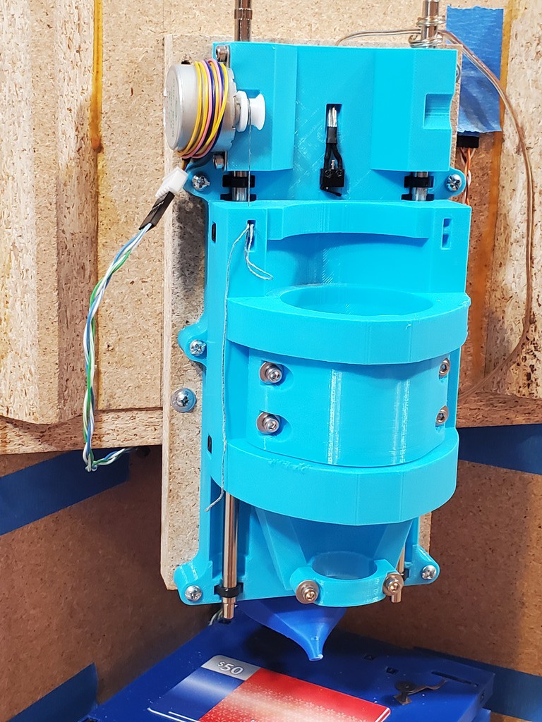
install Y motor
The Y motor fits in the big rectangle on the bottom side of the middle part. It should have clearance along the sides but fit tightly end-to-end. It will likely deform the small wall at the motor end a little but take care to avoid breaking that.
Spin the leadscrew and backlash adjuster to move the motor's slider to the motor end of the screw and move the backlash adjuster to the opposite end, as in the pics below.
Insert two ties for the motor through the middle part and also through the motor frame underneath the two fixed rods before completing the loop back to the tie heads.
(clearly I hadn't taped the switch wire back yet -- apparently it was behaving well)
Rotate the motor into place while drawing up the ties hand tight. Then check that the motor fits flat and tight into place at both ends while tightening the ties up hard. Also add the tie behind the motor to capture the motor wiring for strain relief.
pre-set Y lower rod
Insert two zip ties through the bottom part.
At the end between the switch and bearing, draw the tie down to a loop that is not too small nor too big but just right. An easy way to do that is to lay a rod diagonally across the top surface of the part and draw the tie down over that.
Close the tie around the other end, and pull that one firmly hand tight. You want it tight enough so that you can handle that part without dropping the rod out. Leave both tie tales.
(The part uploaded here actually looks more like:
)
pre-set Y upper rods
Insert four zip ties through the middle part.
(...now I have the X limit switch cable taped up)
Set the not-so-tight ties at the motor end by pulling them down over a rod laid diagonally across the surface of the part.
Pull the ties at the other end firmly hand tight, enough so that the rods don't fall out. The heads of ties on the left are slightly recessed, so you may need to use a tie tool to pull that one tight enough.
That's all the parts for the Y axis. This is a good place for a break if you need before getting into the next sequence.
heads up
You have no springs installed. You believe there are no springs in the following photos. RIght?
Y axis assembly
On the lead screw, check that the slider is against the motor (just in contact, not jammed) and the backlash adjuster wheel is at the opposite end against the bushing (just in contact, not jacking the screw of its bearing).
Pull the three rods half-way out.
Lay the two parts side by side as shown below. Bring the X switch cable (if installed) across and start the connector through the angled hole in the bottom part
This is easier to do than to describe: While folding the bottom over the middle like a book page, feed the switch cable through the bottom part -- which really means the switch cable doesn't move much while the bottom moves around it.
When the bottom part is "folded" over onto the middle, slide the bottom (which is on top) to the left. It should meet a hard stop where the bearings hit the end of their clearances.
Line up the end of a rod with its corresponding bearing and, carefully, work it through the bearing.
Beware: the rod and bearing aren't really aligned at this point and the end of the rod can do bad things like strip out bearing balls. Go slowly and carefully until the rod end clears through the bearing. Nice chamfer helps but I don't know how much is safe enough to not care.
After the rod is through the bearing, work the end into its V-block and under the now-buried tie that is not tight. You may have to lift a little, and not squeeze the two parts tight together, to get the end into the V. Then hold it down to get it under the tie. Make sure the rod end goes all the way to the hard stop. Leave the loose tie loose for now to allow a little float for fitting the remaining rods.
The rod in the photo is a little long: it is all the way in while also overhanging the visible end a bit.
Again with the remaining rods: carefully through the bearings...
... then fully into the V-blocks, under the loose ties, and all the way to the hard end of their clearance.
With the slide fully extended as shown, pull any slack out of the switch cable then let it relax and give back just a little slack. Hold the cable with a fingertip or some tape right where it comes through the bottom part.
Now you should be able to run the slide freely from end to end. It should stop sharply at both ends with hard contact. There should be visible separation between the drive tab and the lead screw slider at the hard limit of extension, and between the tab and backlash adjuster when hard closed.
Close up the slide to its hard limit, then push it hard against that limit to force the bearings to the limit of tolerance in their positions. You may feel one or more of them shift.
When the bearings are set against the surfaces that you checked and dressed way back at the beginning, the slide should overshoot "zero" closed alignment by about 1 mm.
From this point you want to avoid hard contact at the opposite limit, which will knock the bearings out of place. If you do hit the opposite stop, just repeat pressing hard against the closed stop. Hard contact at the limits will be easier to avoid after the slide gets coupled to the lead screw.
Check if you can hear the snap action in the limit switch (if installed). If not, use a meter to monitor continuity and verify that the switch works (which would be prudent even if you can hear it but that's not the point at this point).
Carefully find where the switch just snaps over open or closed. If the overshoot shown above is close to 1 mm, then the switch should toggle (mechanically close, electrically open) when the overshoot is about 2/3 mm, or just before hard contact. Carefully reversing back from that position, the switch should revert when the overlap is about 1/3 mm, or when about 1/3 mm back from where it toggled.
The main thing is that the switch (if installed) must toggle before contact with the hard limit. Secondary to that, it is meant to toggle between "just" and about 0.5 mm before hard contact because I like a short limit pull-off distance because the axes are short. If it toggles closer to 1 mm before hard contact, that's uncomfortably close to the switch body being the hard stop. So the main main thing was that the switch body wasn't ever the hard stop in the first place because if it was then it wasn't anymore after pressing to set the bearings.
For easier handling, secure the slide closed with a piece of tape across the two parts on the side parallel with the axis. Also wrapping the limit switch wire around to the top side and taping it there will help keep it flat from twisting.
Check that all three rods are pressed all the way to the hard end of their clearance, and fully tighten the six zip ties.
Use the short tool for this tie because the long tool leaves only the thin end to grab.
Yay. That was a bunch of tie-winding.
dress the X limit switch cable
(if installed)
Flip the Y assembly over. Pass the switch cable under the bar at the end of the opening as shown:
For convenience you may want some tape to hold the cable.
Note the slide will probably not run freely because it will probably push the cable up here approaching mid-travel, where it will jam instead of pulling back down. That's ok. It won't happen when the stack is attached to something else.
Fully extend the slide. You may have to hold the cable or help it feed back down while moving through mid-travel.
Insert a zip tie through the position exposed by fully extending the slide, turn it back up and through again, capturing the switch cable.
While holding the slide at full extension, re-adjust the position of the cable as before: pull out slack, then let it relax and take back a little slack. Tape over the opening to hold the cable in the position it will take when the unit is attached to another surface. Verify that the slide will rest against the end limit with no spring-back from the cable. Adjust if needed. Pull the tie tight enough to keep the cable from sliding without cutting the insulation.
Cut the tail off flush to let the slide move.
Repeating the process as with the Y switch cable, zip tie the connector housing in place against the ridge behind it, pull slack out of the cable and lay it into the serpentine path, and lead the rest of the cable around the pegs as needed to use up slack.
A nicer piece of tape over the cable opening will keep the slide easy to handle as a unit by itself and, in my experience, isn't too thick to leave in place when mounting the axes for use.
When it's all buttoned up and right-side-up, make sure the slide runs end-to-end and there is no spring-back at either end.
preview
While we're here: a preview of how the rest of this deck-level cable & connector dress will work when we get to it. That's the "wireguide" part on the left. This also shows design detail committed to the 300 mm x 0.1" cable type for the motors (when I started I think that was the only type available). If you have 200 mm motor wiring (do four loosely parallel wires count as a cable?) and you want to fit your motor wiring into this scheme, a short extension with a "DuPont"-like housing will fit where the white connector is but will probably need some filler under it to keep it in line with the constrained mating connector.
Either an option specifically for 200 mm x 2 mm motor wiring or a committed switch to that type might happen.
X axis
The X/top axis goes together pretty much the same way, but simpler because switch wiring is all done. In this part I'll list all the relevant headings from the Y axis, and insert some things that differ. Hopefully that will help track when to check back here while reading there.
like Y axis but...
install bearings
Maybe you already did.
The ties for the lower bearings enter from the sides like this.
install [X] motor
These two ties would have been easier to insert before I put the motor in. But I didn't do that. So I don't know whether or not that would have interfered with installing the motor. I think not but ?.
Secure the motor wires like this.
I've wrapped tape strips around the wires to protect the insulation where ties will land on them. That might be a good idea for the limit switch cables. However it may be hard to mark where the tape should go in some cases like the upper tie for the X cable.
pre-set [X] lower rod
Extend the Y axis for access to the zip tie locations. If they're hard to insert, it may help to bend some backward curl into the ends of the ties.
pre-set [X] upper rods
When inserting the tie under the arch brace, you may get it to follow the arch over and turn back down through the top part by itself. More often I find it helps to break that into two steps: first send the tie through out the inboard side of the arch, then turn the end down to send it back through again. It seems easier to get the loop back under the arch before fitting a rod but not impossible to do with a rod in place.
[X] axis assembly
Pretty much same as the Y axis.
done with that part
Yay!
Now you have two unconstrained axes.
From the laser-cut slide context, here are some comments about checking
off-axis stiffness (which directly follows the first but here's a label for clarity)
Th text includes some stuff specific to the laser-cut context so you'll have to filter that. The part about testing under load is a little complicated because you have a stack of two axes which makes it harder to support and load just one axis.
The "off-axis" discussion has less context-specific noise.
springs exist again
note: once the springs are in they are vulnerable until adjusted at least pretty close to right. I've made a mid-stream change here to delay installing the springs which I think helps to avoid complexity earlier in assembly, which means I've only tried installing springs after assembly once and didn't take pictures.
install Y spring
I suggest starting with Y because it's easier to see.
It's a little tricky to get the spring in with the screw in place, but doable. I don't have a repeatable method yet. Here's some points:
there is a hazard of damaging the screw thread while crashing around it with tools. I'll suggest protecting it with e.g. a bit of tape.as well as just trying to not abuse it
I made a 'recovery tool' from another paperclip by bending a small hook in the end - that helps to pull the spring back out after an unsuccessful attempt to install it
I used fine needle nose pliers to hold the 90º bend at the end of the moving arm so that I could twist the end as well as move it around, then while holding by that corner put the spring in place with the moving arm lifted up into the wider clearance opening while torquing the perpendicular end down so that the end of the wire at least landed on the drive tab if not actually through the slot. once on the face of the tab it was easy enough to push it toward and into the slot
set initial Y backlash
This is just to get into the ballpark, not to fret minimizing backlash. This protects the spring by getting interacting parts into a "safe" configuration.
To begin with, the backlash adjustment is essentially set to backlash=range of motion. But it doesn't really count as an "adjuster" until it's adjusted down to much less lash.
You should be able to "roll" the leadscrew with your thumb. If the screw does not turn easily, a likely reason is that the backlash adjuster wheel is jammed against the frame at the non-motor end of the screw. Turn the adjuster toward the motor end until there is visible separation between the adjuster and the frame at the not-motor end of the screw.
Roll the screw to move the slider away from the motor a few cm. Expose enough screw between the motor and slider so that you can roll the screw from there.
Roll the adjuster wheel toward the motor to close up the space between the adjuster and the slider.
When the adjuster meets the drive tab, it will run into the side of the locking spring. Take care to avoid force on this contact which can bend the spring.
Put a bit of tape over the screw near the adjuster (suggested) and use a small screwdriver or such to compress the moving arm of the spring so that it clears the adjuster. Also keep the tool out of contact with the adjuster. As shown below, the small screwdriver compresses the spring while also avoiding contact with the adjuster.
Now you should be able to roll the screw, which will move the slider, without the adjuster moving on the screw. Roll the screw to move the slider up tight to the adjuster wheel, pinching the slide drive tab between. Release the spring.
(probably not that close to the motor)
If you have brought the slider and adjuster close enough together to keep the spring from slipping off the adjuster wheel, then the spring is protected from being bent. If there is enough slack to allow the spring to slip off the screw, then repeat compressing the spring to move the slider without moving the adjuster to close up the gap.
If you can also roll the leadscrew freely so that the slide moves, then you're done with this.
If the screw is jammed, then the adjuster is too tight. Using a small screwdriver or anything that can get traction on the edge of the adjuster wheel, turn it several notches ccw to liberally open up the adjustment to allow free motion.
However slowly, you should be able to move the Y axis by rolling the leadscrew. If you have a motor driver set up already, you should be able to operate the full range of the axis -- a little more than 75 mm -- and read the limit switch.
You might want to close up the slide for convenient handling -- although it is some inconvenience to do so without power.
set initial X backlash
Set an initial backlash adjustment for the X axis in the same way.
For the X axis, you will have to work closer to the not-motor end in order to keep enough screw exposed to be able to roll it manually.
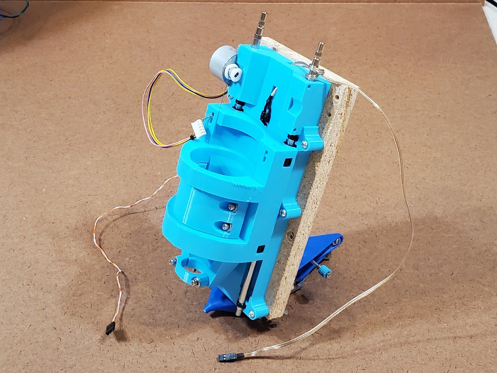
Assembled!
That pretty much completes mechanical assembly of the X-Y stage.
If you have electronics ready, you should be able to operate the axes. The range of motion should be a smidge over 75 mm -- enough to safely use 75 mm.
If you installed limit switches, you should be able to read them. The homing cycle homes the Z axis first, so homing (and therefor soft limits) requires a built Z axis (or crafty application of a screwdriver between the Z limit input and adjacent ground).
Also, you'll need power to close up the last finger-width of the X axis.
electronics and Grbl config
TODO expand this -- and probably move it all to somewhere else.
info for Z axis included here for now
drivers
motor current: ~300mA for X & Y (note for later: ~100mA for Z) -- check actual sense R value
microsteps (currently running XY=8 & Z=2)
grbl
timeout ($1=255 for none - because Z)
motor step direction $3 if not solved in wiring
steps/mm $10x = (40 x microsteps for XY) (~80 x microsteps for Z but measure (and consider reciprocal))
max speed $11x (e.g. 1500 mm/s XY, 1000 mm/sec Z conservatively)
accel $12x (e.g. 75 mm/s^2 XY, 50 mm/s^2 Z conservatively
grbl w/limit switches (optional)
note if you're running grbl on an Uno-like controller (atmega328) with a Protoneer-designed "CNC Shield V3.0" interface board: there is a pin labeling mismatch between current grbl software and the older hardware design
connect Z limit input to the pin labeled for SpinEn output
if controlling spindle power from grbl, take the Spin(dle)En(able) output from one of the Z limit input pins
after Z axis working too (or practice faking /break/make/break/make timing for Z limit)
$5=1 if switches wired NC (recommended by grbl wiki because switches usu fail open)
max travel $13x= 75mm XY, ~50mm (check) Z
homing locate feed ($24=50 e.g.)
homing seek feed ($25=max -- ok to crash hard at limits)
homing switch pull-off ($27=1 (mm) should work)
homing enable ($22=1) & direction ($23=3 probably)
soft limits enable ($20=1)
I'm running without any shielding or filtering on the limit switch inputs; sometimes I have to "home" twice because the X axis stops short on the first try; lately I'm thinking that might be because my limit inputs pick up more noise than I was aware of, which has been ignorable because I use soft limits only and not hard limits; dunno what if anything I'll do about that; will ask Mr. Oscilloscope before trying anything because the X homing short stops that happen in my setup are suspiciously reproducible
dress motor wiring
If managing the motor wiring, which moves, isn't a problem in your application, then you may have no need for fancy cable dressing. I wanted the wiring in close, snagless, tied down, disconnectable, and not using deck space around the back-left corner. The limit switch cables (if installed) are already internal. This part describes dressing the motor wiring.
The X motor will need an extension. The middle part has features specifically for securing that connection to the 300 mm x 0.1" type of motor wires. 200 mm wires connecting to a longer extension can follow the same path with improvised tie-down details.
If you have 200 mm x 2 mm motor wires, and haven't printed parts already, ping me for STLs with different features that might, or at least are intended to, work better for the 200 mm wires.
For 300 mm cables, make up an extension from 35 cm length of wire for a finished length around 33.5 cm between connector housings.
Note: as of 2023/2024 it appears that maybe all motors ship with 200mmx2mm (PH) wires & connector regardless of "type" description, so future revisions may assume that as default.
For 200 mm motor wires, you'll need a longer extension but I don't know how much longer. And a different connector on the motor end.
I've wrapped small bits of tape around the motor wires where they are held by zip ties to protect the wires. It seems like a good thing.
Anyhow... getting started:
Tie the X motor wire at the corner of the middle part so that it makes a relaxed 180º bend from horizontal at the upper level to horizontal at the middle level. It should look like this with the axis closed:
And the same bend upside down when the axis is fully extended:
Run the wires down the side of the middle part with enough tension to pull out slack, and wrap where they pass the zip tie cutout on that side.
Uh, I didn't take a picture of this detail for attaching the connector.
Or a closeup of the connector...
The connector has a pair of "blade"-ish projections on one side. They fit in the highlighted depressions.
While holding the connector in that position, draw the wires toward the motor from there and wrap again where they pass the zip tie point.
Insert a tie (easiest to go in the bottom & out the top -- not super clear in the pic) and loop the wires to capture the two wrapped points.
Connect the X motor extension and secure both the motor wire connector and the extension with a tie. Ties fits in at the top and out the bottom.
Insert another tie at the corner (in at top out at bottom) and capture both the X extension and the Y motor wires so that they come out the tie together along the side of the middle part.
Fully extend the Y axis for access to the corner of the bottom part. Tape the "wireguide" part into position relative to the bottom part. Or, if you've already screwed down the axes, then go ahead and screw down the wireguide too.
Run both motor cables under the parallel part of the wire guide and adjust so that they lay together and make a relaxed 180º bend from the middle part to the surface. Tape the wires together right at the edge of the wire guide to mark that position.
Free the wire guide and tape it to the motor wires in the same position that you just marked.
Bend the wires 90º and tape them into the perpendicular part of the wire guide.
Now lay the wires into the channel across the bottom of the bottom part with the wire guide in position and tape the wires in place there. Turn the wires up the channel.
The zip tie arrangement for the Y motor connector (the differently shaped cavity nearest the wire entry) is a little more obscure than others. It starts like this:
And closes up like this:
Anchor the connectors and dress the wires the same way as for the limit switches. The Y motor connector fits in the first space and a 4p DuPont-type connector the the X motor extension fits in the second space.
For convenient handling, a neatly placed piece of tape holds the wires in the channel. In this pic, I left a little extra tail on the Y connector zip tie which also helps to keep the wires up in the channel. Just opportunistic; not necessary.
Now you can screw down the bottom part of the X+Y stack and the wireguide. I've attached them to a intermediate deck that attaches to my machine frame, in part because I keep changing the mounting screw pattern and put lots of holes in the previous frame. You maybe won't have that problem.
Again with Y axis closed up.
Installed and connected in the frame that is the other aspect of this project. Easy in & out without disturbing the wires lead up from below, and empty space that might turn into another frame shrink (or not considering other priorities for this project in finite time).
backlash tuning
Tighten until jammed, then back off 1 notch at a time until it moves. Might prefer another notch looser for less drag. Should be able to get unloaded lash under 0.025 mm / 0.001" without disabling drag.
disassembly
one axis at a time.
Before splitting the X axis, clip ties securing the X motor cable to the middle part of the axes and unplug the motor cable from its extension.
Before splitting the Y axis, cut the X axis limit switch connector loose and disengage the cable from the serpentine & peg field.
While splitting the Y axis, cut the tie securing the X axis limit switch cable in the bottom part and pull the cable out from the bottom part to separate the halves.
To split an axis: using something thin enough to fit between the two parts, push the interior rod ends outward until either they're pushed out from under the interior zip ties, or there is enough exposed rod out the other side to grip and pull.
Unless you are sure that you will not want to re-assemble the axis, pull rods out far enough to clear bearings without pulling them entirely free of the remaining tie. There is more margin if you can extend the slide and less margin if you are splitting a closed-up slide.
If you are sure that you will not want to re-assemble the axis, pull the rods out completely.
Separate the slide halves.
reassembly
run the sliders to the motor ends of the screws and backlash adjusters to the other ends.
cut and replace the interior rod end ties and pre-set them as above.
assemble as above.
to split and reassemble the X axis only, extend the Y axis for access to the lower X interior rod end tie.
to split and reassemble the Y axis only, extend the X axis for access to the interior end tie for the motor-side upper rod via hole through the top part (in theory; unproven)
Thinking about making one of these things for yourself?
To get started with starting to get the getting started started to push out sufficient information to inform doing that...
...here's a rough rundown of parts to collect for the CNC mechanics. At this point I've iterated the XY stage design more than the Z axis so I can be a little more specific about that.
̶ ̶I̶'̶m̶ ̶w̶r̶i̶t̶i̶n̶g̶ ̶ I wrote about slicing and printing the printed parts separately. And the assembly process (forward-looking statement ahead...) as a richly illustrated and procedurally detailed Instructable -- which I expect will be not nearly as intricate as for the laser-cut version.
At this point, the scope of this info here includes the CNC mechanics (X+Y & Z axes), which will work in a very simple frame. Writing up stuff to stuff into the more fancy integrated desktop enclosure to follow.
Stuff
PLA
250g for XY table
haven't weighed Z axis or (optional) fancy enclosure accessories
bearings
10 x LM6UU
6 for X+Y; 4 for Z axis
generic "brands" appear to be all the same inconsistent quality; buy more and select
MSM bearings appear to be a clear step up from generics for not so much more coin
(2 x 8 pcs cost <$1 more than 3 x 4 pcs at 16 Sep 2023 pricing)
I have some scavenged 1.6 mm x 4.8 mm x 0.5 mm pitch
pitch is more coarse than coarse M1.6 and I haven't found a source for any similar
1.6 mm is just a hair big for a mild interference fit, which is fine, but suggests 1.5 mm would be more "correct"
#0-40 x 3/16 in. thread-forming screws for plastic look like a good fit and are widely available from many vendors -- in lots of 10,000
McMaster-Carr lists #0-42 x 3/16 in more accessible quantities, but still kinda spendy with shipping.
#0 diameter is 0.060 in. which is 1.5 mm
found a source? please say so.
wire e.g. 24AWG speaker wire, heatshrink, etc.
X: 25 cm (10-ε in.) between switch body and connector housing
Y: 13 cm (5+ε in.) between switch body and connector housing
Z: tbd
cables made to length because cable management designed into the XY stage assumes:
wires routed internally to 2p "DuPont" connectors in the stage base
2p extension wires to the controller
so the interconnect can disconnect at both ends -- for sanity in dense packaging
gender reveal?
I'm currently using female connectors on the switches because the Protoneer-designed CNC shield uses male headers and using connectors that could connect to the controller seemed like the thing to do -- plus M-F extensions where needed
but might change to male pins on the switch side to avoid waving bare input pins (or motor power pins) around when unplugged -- then F-F interconnect required but nothing lost with connectors fixed in the mechanics that physically couldn't connect to the controller anyhow
but the F 0.1in connector on 300 mm motor leads will still be F
which is maybe another reason to design for the 200 mm / 2 mm leads instead
and inline M connectors for the 2mm JST-PH F connectors exist (unofficially? i.e. appear to be not a JST product)
if you don't already know/have what you want to use:
~USD10 complete kits of (clones of) Arduino UNO + Protoneer CNC shield + Pololu A4988 stepper drivers exist
example (whoa: $2-$5 "welcome deal"s for new AliExpress users; dunno if that's real or not)
not DRV8825 for this low-current application
but STSPIN220 drivers would rock for this low-current application... I think... maybe
four motor drivers if you think you might want two Z motors
i.e. not a Nano/v4 kit for three drivers only
note all 0.1" male header pin connections, so plan for corresponding "DuPont"-type connectors
wiring
if you use a Protoneer-type CNC shield and get "type A"-wired motors then connections will be all M & F "DuPont" type wire terminations, which might be a welcome simplification, but...
It looks like at least some sellers now (2023/2024) ship "type A" motors with "tybe B" wiring without comment or updating the type-A drawing or photographs
"Type-B" motors (and now at least some if not all new type-A) use JST PH connectors with 2.0 mm pin pitch; JST designed PH for wire-to-board connections but someone has decided the world needs a mating inline connector should you want to keep and use the PH connector
soldering wires to chunks of 40p header strip looks cheap and easy, but I haven't found a way that isn't fragile.
At this time, this log page describes printable parts for the XY stage. Z axis and other accessory stuff to follow Real Soon Now. STLs today; I intend to share the CAD later after a think about how much clean-up it will get.
NACA duct FTW
My 3d printing experience is narrow. PrusaSlicer 2.5.2 defaults for Ender 3 Pro w/0.4 mm nozzle define my normal for whatever I don't mention below.
<update>added PrusaSlicer version 2.5.2 because I just tried 2.6.1. While it looks smarter about bridging over infill under top layers and wall thickening, 2.6 apparently just generally fails at bridges over voids - has since alpha. Bummer.</update>
These STLs reflect conservative changes, presumably improvements, since the last versions that I've actually in fact printed for myself as of writing this.
Big parts
XYbottom - "General" parameters
XYmiddle - "General parameters
XYtop - "General parameters, and:
slice/print upside down
optional to make stiffer:
break into parts (not objects)
inner part set perimeters=11 (whatever gets the slicer's attention) to generate internal structure
I haven't assessed the practical benefit beyond making the part qualitatively less bendy
Small parts
XYwireguide
two perimeters
XYtietoolshort, XYtietooldeep
two tools; print one of each
slice/print big end down
fill gaps on
100% rectilinear infill
XYbladj
print two parts
slice/print flat side flat
Arachne perimeter generator
9 perimeters (big number = all perimeters)
tap for M3 thread
Less Briefly:
Single perimeter
10% fill
thin walls
Instead of printing lots of plastic to make parts strong, I started out printing as light as possible to expose weakness in hope of making parts stronger by design first before resorting to pouring in more plastic. So far, I'm still printing light. I think that's a feature. Mainly because printing less prints faster.
single 0.45 mm perimeter + 10% gyroid infill
I'm using a 0.4 mm nozzle, 0.45 mm extrusion width, 0.2 mm layer thickness, 4 solid top & bottom layers, gyroid infill, and PrusaSlicer. I haven't messed with any of that so I don't know that they are "best" choices, only that they're working well enough to let other stuff draw more attention.
I'm using 10% infill because 5% was too sparse to support bridge areas under internal features -- and/or the slicer wasn't extending internal bridging areas far enough to span large gaps in 5% infill. I wish the slicer was smarter about bridging to something in the layer below instead of just spanning an arbitrary offset around the feature to be supported above. Or building an infill edge around the area it wants to bridge. PS is open source, but that's a rabbit hole I'd rather fall into. There are other slicers[a] and I haven't tried any adaptive infill.
PS adds material to thicken non-vertical shells. I get that, but in the interest of printing lighter to see where parts are weak (he says but really means printing faster) I would like to but have not discovered how to dial that back some. Notalone (ooh... "turn it off using Modifiers" in 2nd link).
In the image below:
red marks a ~vertical cavity with a simple perimeter
green marks a moderately sloped cavity with some added solid infill, which adds material (and time)
yellow marks full 4-layer top surface under each rising step, which adds a lot of material (and time) -- I get that you have to do something under the non-overlapping perimeters but maybe not all of this
magenta marks a patch of 4-layer top surface under the flat part -- not complaining about that
PrusaSlicer shell thickening
All that infill around slopey walls adds up to a significant fraction of the total material and time in the part. I expect that most of it wouldn't be missed if it went away. Refs linked above suggest this is specifically a PrusaSlicer thing. How many parts would I have to print to recoup time spent shopping slicers to avoid this?
[a] What about Kiri:Moto? I use K:M for CAM and very much appreciate the author's gift of effort to produce that. When I got my 3d printer I printed cubes with default slicer profiles in Kiri:Moto FDM and PrusaSlicer and the latter was the better. And I wanted to print stuff more than I wanted to learn slicer tuning. As a K:M CAM fanboi, I feel a little dissonant about ghosting K:M FDM for no good reason. I'll likely revisit that at some point.
Thin walls + specific reinforcement
The bottom doesn't have to be super stiff because it gets screwed down to something else that is, presumably, more stiff. The thicker middle part is a fairly stiff box structure by itself. The top part not so much. A robust spoil board well attached would stiffen that, but I haven't tried that yet. The "arch" part that projects down into the "middle" space (near corner in this pic) does a lot to help brace a hinge-like stripe of thinness that runs across the top there -- while keeping up the theme of strength from shape instead of density. If I'd thought of that first, I maybe wouldn't have bothered to try a few iterations of adding an internal shape to persuade the slicer to generate specific internal structural reinforcement instead of generally more perimeters or denser infill. But it's there so if you convince the slicer that it's a distinct part with a perimeter, which also implies another perimeter around it in the main part, you'll get some internal reinforcement stringers.
internal structure: "one perimeter" = five perimeters along edge on the left in this view
To the slicer, that's two adjacent objects and their perimeters don't overlap. The reinforcing shape is two overlaps thinner than a two-perimeter wall. With "thin wall detection" off, the slicer lays down two perimeters in there anyhow so the volume/density/adhesion of plastic in that space should be the same as in a four-perimeter wall. In theory.
Bridging
Lots of bridging. Over internal voids, mostly for zip ties and cable routing, and over all of the upside down features on the bottom of the middle part.
There are lots "upside down" features. The whole bottom surface of the middle piece is upside down and lots of internal features have upper surfaces. I can't use support in internal features or under surfaces that should be clean and "precise" (relatively for vanilla FDM). So, generally, I've tried to design for printing with no supports. That's been something of a learning curve. Fortunately, the parts that most need to be "precise" are V blocks to locate round things and upside down Vs are easy. In theory. Actually getting clean results has entailed lots of learning lots of ways to not succeed. And, initially, quite a lot of time sitting and staring at the printing printer to see what it was actually doing inside parts.
Slicing bridges
PrusaSlicer, at least, sometimes gets a bridge rwong. I don't know why. It seems quite arbitrary when it happens. A bad bridge might fix itself after seemingly unrelated changes. ?. So I've grown a habit of stepping up the layers in preview to look at every patch of bridge fill over empty space. Fortunately, the preview shows bridges in a contrasting color, which helps with flipping through a bunch of layers until a contrast patch catches the eye. About half-ish of those are bridge areas under voids as the first layer of a patch of "top layer" solid fill (or the actual top) -- a quick flip back confirms whether a bridge area spans open or filled space i.e. above or below a void.
Modeling for bridging...
...and clean corners whether upside down or right side up. In other words, clean details.
I started with some minimal parts just to see if the V-block and zip-tie idea would work at all, and work when printed upside down. It seemed possible in principle because Vs -- 45º slopes and short bridges -- should be easy to print upside down. In principle...
not a V-block
Solving that is how I got into using the Classic perimeter engine instead of Arachne, turning off gap filling, and modeling details around shell thickness, layer height, and overlap math in order to make geometry that would slice predictably where details get close to the dimensions of an extruded line of plastic. Also growing a better feel for geometry that doesn't work upside down and modeling details that are possible to bridge cleanly.
I've probably over-specified a lot of geometry just because I haven't tried to work out which details actually matter.
Alternatively, maybe I (you?) could learn more about what Arachne does and how to model Arachne-safe details, which would probably be more dimensionally flexible.
Just a "quick" note about cable management because I'm thinking about it while iterating the 3d printed parts design to print a set that doesn't require artisanal handcrufting to finish.
Wires around moving parts need help to stay out of trouble:
first 3dp printed proof-of-concept -- not even trying to deal with the wires yet
Easy answer: Big stiff loops that can't fit into small places help. And that works fine in a big or open frame with lots of room for (relatively) big stiff loops to move around. If you're just here for the CNC mechanics and don't care about compacting the whole works, then you get the easy button.
But I want more smallness; Crowding the moving wires into less space, without binging complexity, is less easy. Between this project and its laser-cut precursor, I've spun several variations of this basic mechanical configuration and still don't really have cable management solved. Here's the latest XY stage -- the thing I should be iterating into obsolescence instead of rambling here...
progress toward compact cable management that isn't too tedious to dis/assemble
The folded bundle of wires between the fixed base and lower stage cycles back and forth in a vertical plane pretty close alongside the side without getting into trouble. Breaking the 2d motion of the upper stage into two 1d motions keeps the upper part similarly simple while the lower part is just a few more wires in the bundle that's already there.
The visible wires feed the motors. The limit switches and their cables are internal, which was an aspiration that came along with the freedom of 3d printing to make parts busy on the inside.
In that (currently current latest) iteration I wanted to include connectors to disconnect above the deck without pulling any wire up from the lower compartment, and include some provision for managing excess wire within the footprint of the XY stage. Because wires won't be exactly the correct length, and can't be too short, so they will be too long. Especially while "correct length" keeps changing. That makes it much easier to remove/replace the XY stage for whatever reason. I like the functional benefit but that version isn't the answer. Next rev is printing while I'm typing here.
I had convinced myself to stop thinking about wiring the motors internally because that wasn't going to happen without ditching the (relatively) bulky connector on (some of) these motors. My current thinking is that adapting the design to the motor wires & connectors will net-simplify construction vs requiring to mess with the received motor wiring.
(aside: That may change. Especially because there are two flavors of the motor I'm using and differences include the length & termination of wires -- and I just received a 'type A' motor with 'type B' wire length and connector so "be sure to order type A" might fail to make the received wiring predictable.
...now returning to the previous digression...)
The Point
...of this log entry was to note that, while (distracted from) iterating the 3d printed parts to print a set that doesn't require artisanal artishandcrufting to finish, I think I accidentally figured out how route the motor wires internally. That could be très slick, enable a little more compactness of frame footprint, and get more working parts out of the milling debris field. But I really have to not go down that rabbit hole right now. But I don't not consider it anymore.
the update:
The next rev
I really liked how that (above) worked out functionally -- and also noted a bunch of flaws, and reconsidered some deferred questions.
No artisanal handcrufting required:
connectors and Slack Chamber hidden; guide/cover for deck-level outboard cable run.
A couple bits of tape make life easier when the unit isn't bolted down to a surface.
where stuff went
Using "serpentine" strain reliefs for a relatively gentle hold on the cables to answer expectation that they will actually get pulled on -- because nothing holds the DuPont-like housings from sliding out (they're blocked from pushing in). Funny that I made the motor cable channels bigger then put thinner cables in them.
Hmm - the serpentine behind the white connector is superfluous. I guess it's there because this arrangement had to fit 4x DuPont connectors first, then modified for the different housing
in situ
While the buttoned-down look is nice, the real motivation for the little outrigger wire guide is to establish where the moving cables attach to the deck without having to measure and mark. If you like this cable dress from the motors to the deck but don't want to fuss with leading the cables through the base, you can just use the guide to mark the deck and the wires for where to anchor the wires on the deck, then ̶ ̶c̶h̶u̶c̶k̶ ̶i̶t̶ ̶ send it to your favorite PLA reprocessor.
Been racing to get stuff done and falling way behind writing about it. :-/
Here's a quickie look at today's new superpower:
That's some 0.010" (0.25mm) slots in the bottom of 0.020" (0.5mm) slots in the bottom of 0.040" (1mm) slots in a flat spot on some aluminum.
As it happened:
Yes, I have tram issues. Project for another day.
Really it's supposed to be a backlash test. The edges that look like they should line up should actually line up:
But I got carried away with some new cutters from a bona fide cutter monger:
(vs 10/$10 Qi Po cutters)
I imagined that drawing lines on a picture would be a great way to quantitatively assess backlash. But my microscope has non-trivial lens distortion. Eyeballs cope quite well, but not so much the lines on picture idea. The pic above shows my try at antidistorting with Gimp's lens distortion and perspective tools. Taking measures from images distorted to look right is a little suspect, but presumably lens distortions wouldn't let me tweak offset parallel lines into line.
Anyhow, the point is that backlash is usefully small. And, though they may stretch the original "very low cost" theme, real cutters rock.
Gotta say: "MRRF". Haven't written it up yet but MRRF. (MRRF write-up, now published, precedes this log because started that before starting this)
A more expository 2+ minute local TV news exposition includes a brief interview with Sonny Mounicou.
Going to the Big Show
Earlier this year, after convincing myself that the 3d printed CNC core would work, and getting more stuff working inside the box, and sorting some ideas for doing all that better, and looking at lots of weeks before the event, I started thinking I might have something that would more directly interest 3d printing people than the laser cut thing. So I actually booked a hotel room and made a plan.
Then other stuff happened and I got a lot less done than the motivating aspiration, but still had something coherent to show.
I didn't take a lot of pictures. In fact, at the show I took one picture:
While packing stuff for the show I thought to take my microscope for grins. That turned out to be very helpful for people to get the 'wow' of the project. After fiddling with it for a while, I got the idea of taping out examples in an arc around the vertical pivot in the stand, which made it very simple to swing the scope head across all the things. For example, Ryan of MPCNC fame appreciated the closer look.
The microscope helped in part because I didn't really get to keep the mill itself very busy doing its thing. I did manage to cut one little bevel gear that I didn't have an example of. (because I forgot to pack the little differentials!!)
Early on I cooked up the idea of carving the MRRF logo, but by the time I got that idea mashed through CAD to gcode while frequently distracted (the talking-with-people part) it was too late on Sunday to finish, so I just let it run until it was time to pack up and, unsure that I could actually resume the job successfully, took note of where in the gcode I had to pause it.
Later (considerably later, because life) I was able to re-register close enough to perfectly with the incompletely cut workpiece and hack the gcode to gracefully pick up where it left off. It worked pretty well. Here's the end of the resumed-and-completed roughing pass:
The result after a finish pass appears at the top of this page.
Although I was almost continuously at my table and more often than not talking with someone who stopped for a look, I walked away for a bit Sunday morning to collect an offer of free filament. I recall a drone flying overhead as I walked away -- which turned out to be the fly through video that shows my table sadly deserted.
There's the back of a display showing example vids and images (some dated and some current from the new machine), the mill, the blue printed parts for the next rev that I hadn't had a chance to assemble before the show, the microscope and light, my laptop probably with the MRRF logo CAD open, etc.
The filament vendor had already packed up and cleared out, so my absence was for naught.
I enjoyed talking with lots of people, which also helps break up crusty thinking. I didn't do a very good job of retaining who spent time at my table talking about what. Sorry if you're reading this.
Things I learned from talking to people:
If quicker tool changes matter, multiple rotary tools each set up with one needed bit could help speed up tool changes
so I'll have to check repeatability of the Z axis tool clamp
for double-sided parts, using a thicker spoil board could relax how precise holes need to be for locator pins if the holes can be deeper
While helpful for proof-of-concept, the packing tape hinges really don't count as a durable assembly
but even with good brainstorming help, we didn't come up with a good upgrade
but I think maybe I've found something that could work (in hand but not tried yet)
This log entry describes a completely new enclosure that I kind of accidentally built in the middle of getting this 3d printed re-do of the CNC mechanics to work well enough to believe that it would actually work.
I've copied it here from #"Desk Accessory" CNC Milling Machine, where it's dated from two days ago, to bring it into this project that I plan to enter in the HaD Prize Gear Up Challenge.
Earlier this year..
The CNC mechanics of #Minamil: a minimal CNC mill had been working encouragingly well for a while but depended on a bunch of other stuff that could be integrated into a compact enclosure but wasn't. A few months ago I made [this] new XY stage with longer leadscrews that couldn't fully extend within the frame/enclosure I was using at that point. In the parallel universe where I have better executive function, I simply put the new CNC mechanics in the old box for initial testing with useful if not maximal X range and -- as it turned out -- more work to get it the new thing working as well as the old thing. Instead I started thinking about a different enclosure and that got out of control for a while before I got back to getting the actual CNC part to work.
That was a usable first draft and useful for finding pain points to motivate a second try.
Unfinished bits included:
switched AC for spindle still not inside the box, but at least consolidated to a hacked power bar
negative ventilation motor wired but filter & outlet not done
In addition to supporting the CNC parts, the box encloses spaces in the top and bottom. AC power stays isolated in the top part. The bottom part is divided into space for the air filter/fan and space for the control electronics.
A scavenged unenclosed 5V/12V supply with output through PCB headers and lots of little wires doesn't help the top end look any less chaotic inside. At least it keeps AC away from the rest of the works.
I figured everything should fit and I've already learned that wires fill more space in real life than in diagrams, but once again underestimated the challenge of connecting lots of things in a small box.
Doing this once spawned ideas for how to do essentially all of it differently. I really super very much wanted to do a completely new build that I thought some people might appreciate at MRRF this year -- with fairly specific plans and seemingly adequate time. But life. So less time. So when I did get some time I spent it furiously scrambling to finish just a few betterments before MRRF instead of writing log entries. At least I took some pictures while tearing down the "first draft". Then MRRF. Then more life. RIght now I have some time, and a backlog of ideas. But with this year's HaD Prize "Gearing Up" challenge on, it's time to squeeze in some writing too...
New box, and first try at getting more stuff inside the box
yes, the picture is a repeat -- because a bunch of words got in here after the first instance.
Part of the main idea is for the closed box to be just another box and trivial to stash away wherever without snagging or squishing vulnerable bits.
With the box closed up, I want four flat sides like a plain box with no projections. No hinges, no latches, no buttons, etc. And I want it to be not fragile. In this iteration, moving the hinges away from the corners makes those two corners not fragile. Also the corner where the doors meet is not fragile in compression because the solid panel of each door transfers the load straight into solid material at the hinged corners. For a quickie solution in this case, a single magnet and iron peg (i.e. screw) hold the doors closed, but I have ([1]had?) a plan for a more robust closure. The block in the corner where the doors meet I cut wrong. The idea was to have a single solid piece with the bottom end aligned to rest on top of solid material next to the XY table and the top end in the plane of the top of the box so that, along with the two solid sides of the square, the top can bear load if whatever lands on top has a flat bottom.
Also I have ([1]had?) a plan to replace the metal top clips that hold the straight sides straight when "open" with a closure for the enclosure that would hold the two panels perpendicular where they meet when functioning as a enclosure for the running machine. That's a little tricky because stuff can attach to those panels only on the outside (the sides that face outward in the "open" but "closed" configuration -- err, top-right in the montage above :-/ ).
I really like how this arrangement (and modestly improved next rev) closes up into a very solid box of flat sides ( ̶ ̶i̶n̶s̶e̶r̶t̶ ̶ imagine gif of me vigorously bashing the fragile-looking corner where the doors meet), but it's not clear that clear packing tape hinges can really be a thing (you know that box that's sat by a sunny window for a couple of years...) and I haven't yet found a more respectable hinge with similar function. So this might fade into something sadly less elegant. (...accidental segue to footnote...)
[1] But I might change how the doors fold which would change how the closure works, which would make that idea obsolete. So maybe not building that will be the answer anyhow.
The control electronics all live on a long "sled" that slides in from the back. The blue square with the fan. Status LEDs show through the front. Electronic switches on the sled line up with captive mechanical pushbuttons in the side panel. More pix below.
The control buttons, including push-on-push-off switches, are (supposed to be) slightly below flush with the panel side when "out" and surrounded by fingertip-size relief to allow pressing them "in". Except for reset which is shorter with less relief around so that it requires more deliberate effort to press.
They are out of sight but easy to reach (assuming operation with the solid walls to the right and back and the enclosure panels to the left and front). The hold and resume buttons are at the heights of index and middle fingers for a standard hand (i.e. mine) resting on the table.
"Plans" include adding more tactile cues to help fingers find the buttons quickly. Mainly to confidently distinguish the hold/resume/motors column from the abort/reset/controller column without feeling around. Another idea was to make a removable oversize cap for the abort button to hit with a blind slap then remove and stash in the box when not in use. That might work as the 'tactile cue' if not too sensitive to off-axis touch by a finger sliding along the panel surface.
This arrangement might turn into just a bigger hole in the side panel to expose a solid control panel on the sled. Reasons for not doing that in the first place have faded.
Probe input wires hang out the back because I forgot to decide where to put an accessible connector in the front. Probably because I had "3.5mm jack" stuck in mind and I'm out of panel mount 3.5mm jacks. Meh.
Top: AC / high voltage stuff
I haven't measured current draw for the CNC electronics and (very small) steppers, but I think it's well under 1A. The main DC load is the big fan to suck lots of air through a non-H(igh)E(fficiency)PA filter. That's labeled 3A, but I measured ~1.5A running. Spin-up, although slow, is still faster than the meter I was using so I won't bet that it's any less than 3A. Plus a couple of smaller fans (chip blower & confined electronics). DC draw in steady state might be as small as ~2A. Considering low precision guesses and fudge factors, call it 3-4A. And power supplies that don't specify "yes, Virginia, this really will put out {x}A forever even in a stuffy box" probably won't. That got me to looking at 5A (60W) supplies and up, which looked like I should expect to put a "real" supply in this space rather than a barrel jack.
For a first whack, I found a 5(ish)V+12V power supply from a dead TV that fit.
I want to keep this space isolated from the work area so no vents in the bottom or "front" (diagonal) faces. I didn't know yet how I was going to do the spindle AC stuff or wire a more permanent DC supply that probably would end up needed switched AC (this one has standby 5V and an 'enable' input so I could get this far without an AC switch) so I didn't want to perforate the other two sides yet either. Sticking a power supply down in the bottom of a deep hole seemed a bit rude. So there's another 12V tap and a little fan down there to stir air and make me feel better. I haven't finished the air filter yet so the big fan remains idle and this supply probably never made noticeable heat anyhow.
The spindle enable signal runs up here from the controller below and there's a 12V tap for a relay. But I didn't get that part done. Instead the dangling wire combines the enable signal and ground from the relay supply to drive a hacked power strip for a half-way solution. The power strip has screw keyholes and I could have stuck it to the back of the box if I had reason to carry it anywhere at the time.
Supply and signal wires drop through a small hole (mostly full of wires, not a vent, and ideally would have some gap fill around the wires) in the corner and run in a tight bundle (an overwrought experiment in flat lacing -- would have been better if I'd read up) down the corner of the box through the messy place to the electronics in the lower compartment.
Another look at what was in the top compartment:
This part was all very "first draft" and already gone. But that's another log.
Laced bundle:
down: 5V/Com, 12V motor supply, separate 12V/Com for the big fan
up: power enable (12V & more 5V), spindle enable
That bundle runs straight down the back corner of the work area to the Grbl sled below:
(shown with Z axis wiring also)
Bottom: DC / low voltage stuff
aka Grbl sled
So, the supply wire bundle comes down from the top to this "sled" that slides into a pocket in the base of the box. Status LEDs line up with holes in the front and switches on the side line up with captive buttons in the side of the box.
And a bunch more wires go back up through the same hole into the work area above. Except power for the big fan which goes over to the other side of the box base.
Push-on-push-off switches:
5V to controller (Grbl on Uno clone + Protoneer-designed CNC shield + A4988s)
12V enable signal to power supply
When the supply is not "enable"d, standby 5V (>6V open circuit - which exceeds "absolute maximum" for the mcu so minus a diode drop) provides enough juice to keep the controller & bluetooth alive. Barely. That load drags the voltage down to I forget what but well under 5V (before add'l diode drop). Setting the "enable" signal to the PS lights up 12V and solid 5V.
The compartment gets really crowded with wires:
bundle from the top compartment
switched 5V to controller
4x 4p stepper cables (support for redundant Z motor)
3x 2p limit switches
2p switched chip blower far
spindle (& chip blower) enable
fat 2p switched vent fan
vent fan enable
2p sled fan
TX/RX to BT module
motor enable to status LED
4x tact switch (hold/resume/abort/reset)
ground to CNC shield (also grounds controller)
Part of making all that fit was running all wires that leave the compartment up to the front of the sled. From there all the wires run in a somewhat parallel bundle about the same distance back to where they go up (or sideways) out of the compartment. Then when the sled is in place there isn't a lot of extra wire in where there's no extra room, and that length of wire allows the sled to be pulled out without disconnecting anything.
Another part of making stuff fit was concentrating the off-controller stuff -- LEDs, switches, fan FETs, BT module, etc -- in a single compact unit with no bulky wire terminals, few 0.1" headers, and lots of short pigtails. Three chips of FR4 perf board hold switches on the side, LEDs to the front and everything else (fan FETs, a few interconnect headers, and lots of interconnect pigtails) on the bottom. Through-hole switches and big FET for the big fan; otherwise SOT-23 and 0603 SMD.
Yeah, that, and ...
I want to get more pictures in here since they're what's left of that build but I need to get past this log entry which means fewer words. Which probably will mean more future forgetting what was what and why. Meh.
Fans
upper/AC/power supply compartment -- described above.
sled compartment
dust suction (switched as "coolant")
chip blower (switched with spindle)
The sled has a fan. The controller probably doesn't make much heat and the motor current is small so maybe this doesn't matter. But it's a crowded confined space. So a fan makes me feel better.
This iteration was a ̶c̶o̶p̶ ̶o̶u̶t̶ ̶ experiment to avoid making holes when I don't know what I want to end up with. The fan exhausts air out. The fluted sign board lets makeup air in past the electronics so that it goes back through the electronics on the way out. Hopefully with sufficiently little resistance to avoid sucking cutting dust in through e.g. the LEDs. I tried to see if blocking these inlets reduced airflow out. Inconclusive. Experiment over. The sled wasn't full of dust after as much use as this version got. Next iteration turned the fan around to pressurize the compartment (with clean air) so dust won't (isn't expected to) be a driver of where to put outlets. Or maybe LED & control openings will be enough.
This was supposed to be fewer words....
Dust suction
Sucking air down into the enclosure and through a filter on the way out worked quite well in earlier builds. ATSM level 2 surgical mask is about the right size and supposed to filter mean micron & sub-micron particles pretty well. But it's far from "High Efficiency". This power-dense counter-rotating fan drives enough static pressure differential to get the job done. It's also crazy loud -- which matters little for an intrinsically loud application.
The fan is wired with plenty of power thru a hefty FET switched by Grbl's "coolant enable" signal. But I haven't made a filter frame or exhaust opening yet. ... must. escape. this. log. first. ....
Chip blower
Blowing a weak air stream from a weak air pump through a tight nozzle directly at the tool tip worked pretty well in prior builds, but that was one of the worst offenders among things that in principle could be integrated into a compact box but was awkwardly not.
I thought some thoughts about that for a while. So far that's lead to fixing a nozzle directly to a "turbo"-type (side exiting) blower and suspending that assembly on a 2dof rig behind the spindle. Found an old laptop cpu cooler for a first draft.
low / thin material:
high / thick material (tight to bottom of Z but still reduces Z clearance but still much more Z clearance than thickness of anything I've tried to cut so far):
max high/retract:
the rig:
hidden vertical-ish slot in moving piece crosses horizontal-ish slot in fixed piece for 2dof
constraint-solving parametric CAD FTW!
Hey look... Is that Z axis attached to a removable frame part?
XY axes
While iterating the axes the mounting screw pattern keeps changing. That means a mess of holes in the prior couple of frames. I've tried to set and keep a uniform pattern, but the uniform pattern keeps changing. Hole entropy only increases.
Also, adding flanges for mounting screws makes the XY table more sprawly, which limits shrinking the overall footprint. Running screws up from below into the bottom of the XY unit would solve that, but no access from below without impractically much dis/reassembly.
Also, I wasn't having great ideas for how to reach the back or right sides with a drill or sensible screwdriver without impractically much dis/reassembly.
Also, I'm more interested in smallness of footprint than shortness of height. So adding ⅝ in. more tallness doesn't break my heart.
So the XY table attaches, from below, to a separate piece of frame material that can be replaced when it gets too perforated...
...and which is stiff enough to pin down with two thumb nuts in the reachable pair of opposite corners.
Actually this "first draft" started with wing nuts instead of thumb nuts. That worked. But they need a lot of room for the wings to swing. This version has the room but I was thinking of a frame shrink before MRRF. When I get to that, it will require something more compact. These thumb nuts are the current candidate for that.
XY cable dressing remains an unsolved mess in this version. There's no room for excess wire below so excess, and connectors, get tapewadded up on top. Also installing/removing this unit requires hauling out the Grbl sled and fishing wires with big ends made of edges and corners down or up through a crowded hole. Lesson: wires that leave the Grbl gaol have to be disconnectable at both ends. Also lesson: unless they're exactly the right length and can be dis/connected in tight quarters, the XY assembly needs some provision for managing a little extra wire + connectors above the deck but not interfering with motion or limiting footprint shrinkage. As a separate concern, the motor wires come down to the deck at a specific point near the left edge; it would be nice to have a more deterministic fixture there.
The Walmart card is my spoil board for now. It's smaller than the usable work area so that's not a complete solution.
The little spring contact under a shoulder screw helps with Z-probing copper-clad board. The springy part contacts the board and the Z probe -- so far just an alligator clip -- can clip to the shoulder screw.
Z axis
The Z axis attaches to a separate plate also. Along with solving screw hole entropy, this also adds stiffness behind the part of the axis that projects below the fixed upper face of the frame so the printed part doesn't have to handle that by itself. T-nuts in the frame make it easy to zip this on/off with machine screws run into threads that aren't fragile. Also, I cleverly marked out and drilled the screw holes in the frame with just the Z base attached to the detached attachment plate. So there's plenty of clearance around the attached base of the Z axis for the screws that attach the assembly to the frame -- provided no steppers or sliding part of the axis are attached. Besides forgetting about motors, I forgot that the moving part is a little wider than the fixed part. It's just possible to sneak the bottom two screws past the moving/tool-holding part, but the motors completely cover the upper two screws. Bah. For slight relief, I've been running this Z axis mostly with one motor (it suffers less from reasons to want redundancy in earlier versions) so at least one upper screw is easy to use and that's not very much less stiff than with all four screws. So hole entropy in the frame will soon increase anyhow. I've already cut a new (what to call it?) intermediate plate that's a little bigger to spread out the screws a little more.
I randomly found a box of wire clips at a resale shop that looked like a good candidate for managing the Z axis wiring where it comes to the front from the vertical run back in the corner. Alas, whatever plastic they are made from is crazy stiff and I have to pry them open with a screwdriver to slide wires in/out without scrubbing the insulation -- without crushing wires with the screwdriver that I'm using to avoid crushing them with the clip. :-/
Attaching the chip blower to the back of the Z axes intermediate board seemed like a good idea at the time. Largely because I didn't want to deal with attaching it to the bottom of the upper compartment of the frame. But it makes the Z assembly much more awkward when off the frame. FITNR.
Ok, that was kind of a failure to use less words. But instead got done with less photo editing.
entirely optional decoration around the "minimal" CNC core
aims to build a complete, compact unit to park on a shelf and use at will in ordinary places
previously a slow "aspirational" project parked at early proof-of-concept
recently bumped with a new build that gets a lot closer to realizing the "desk accessory" idea
This new "Minamil 3dp" project introduces a substantially different implementation of the "Minamil" CNC core combined with fresh progress toward "desk accessory" packaging.
Why spawn a new "Minamil" project?
I think this new design for 3d printed parts, vs laser cut, combined with new work toward "desk accessory" packaging, represents a step change in potential utility to someone who wants the capabilities of a precise little CNC without committing space for a machine and the mess it throws off. Wider accessibility of 3d printing and much more simple assembly make this design more practical to build. A completely new frame configuration and more comprehensive integration into "desk accessory" packaging make this design more practical to use.
And...
I plan to submit this project for the current HaD Prize Gear Up Challenge, where the rules require a new project anyhow.
...from a symbiotic pair of projects-in-progress, spawned a new thing different enough to warrant a new project
and HaD Prize.
this
25 July 2023
Because #Minamil 2dc: a minimal CNC mill has accumulated enough log entries to be difficult to naviigate, ̶I̶'̶l̶l̶ ̶d̶r̶o̶p̶ I dropped this here to stake out space for a Table of Contents in case logs here ̶g̶e̶t̶ got unwieldy.
table formatted table of contents inspired by @Vijay; just chronological for now - because I want at least this for myself sooner than later - maybe add topical structure later... (meanwhile, "Build? Start here" is a topical node)
 Paul McClay
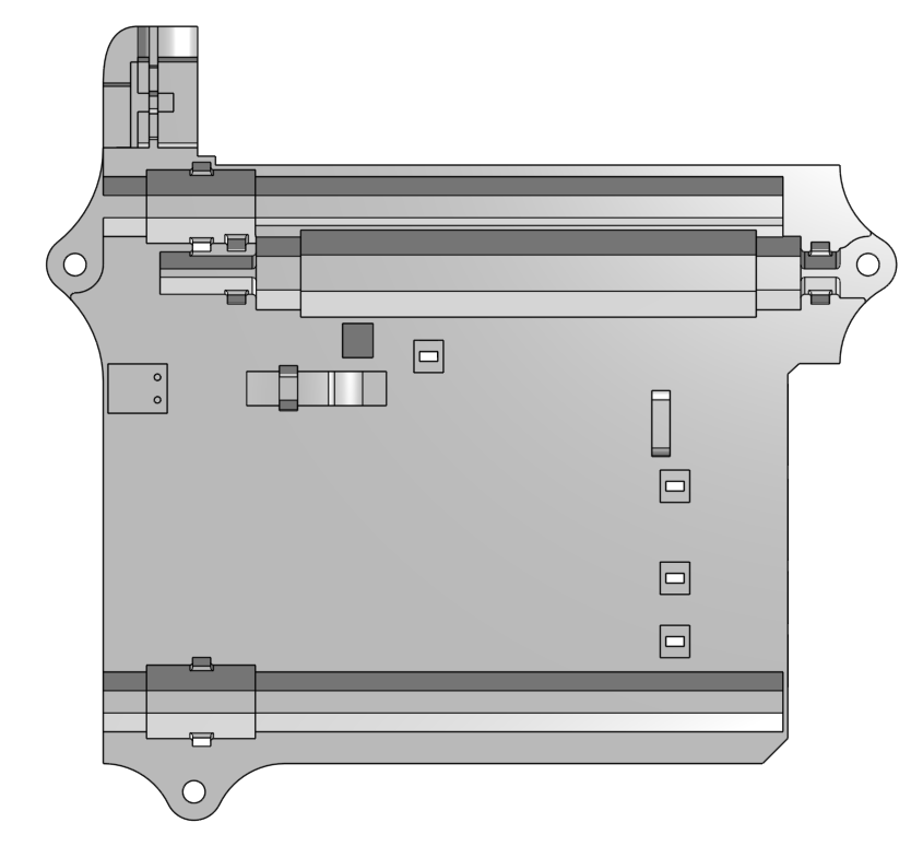
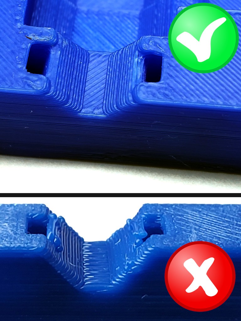
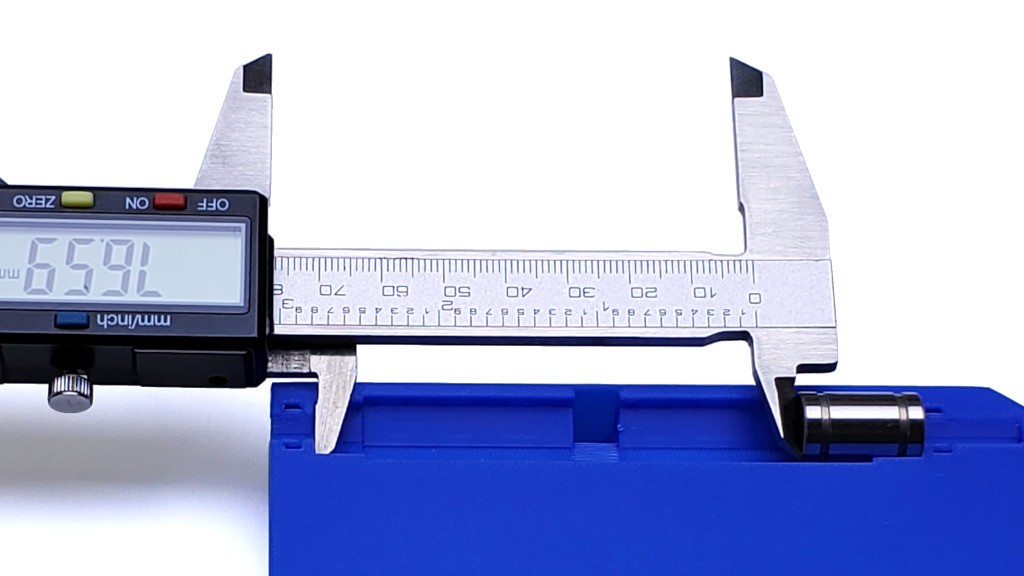
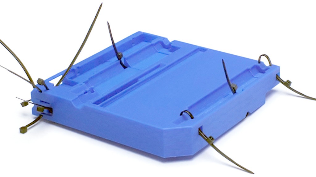
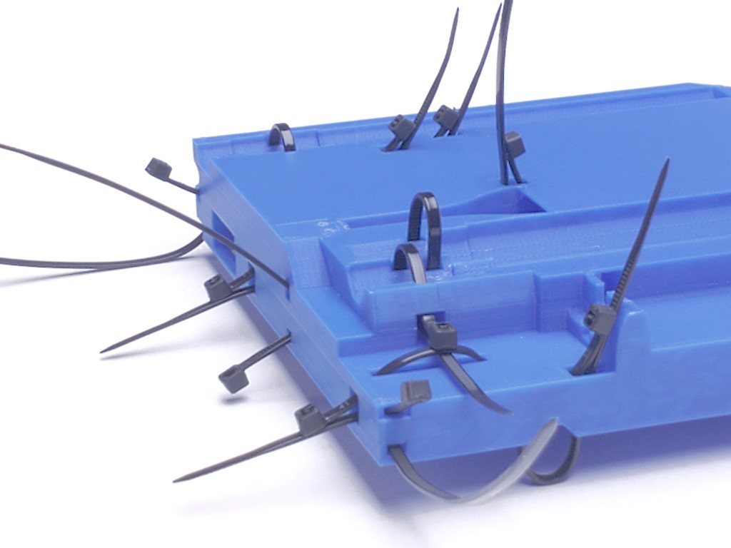
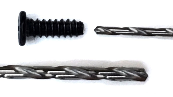
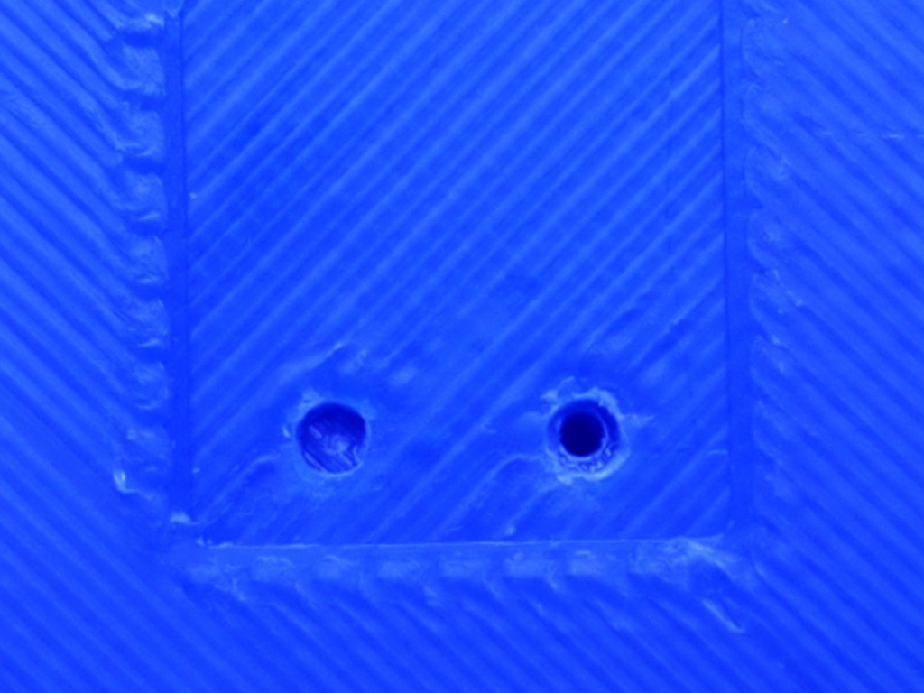
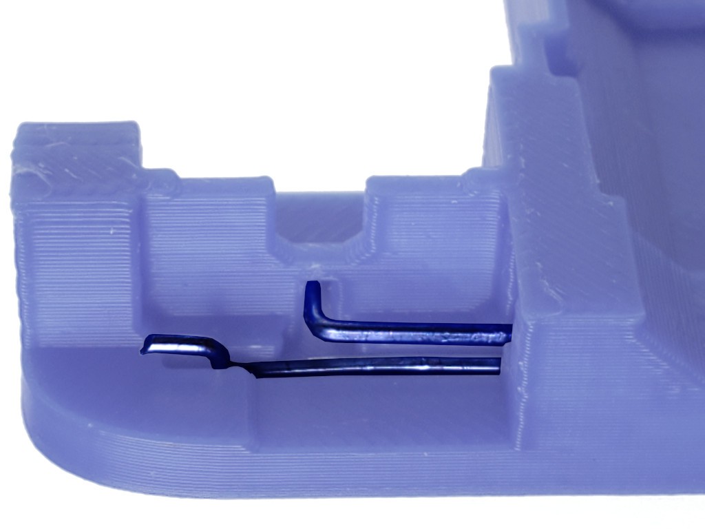
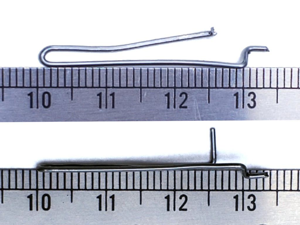
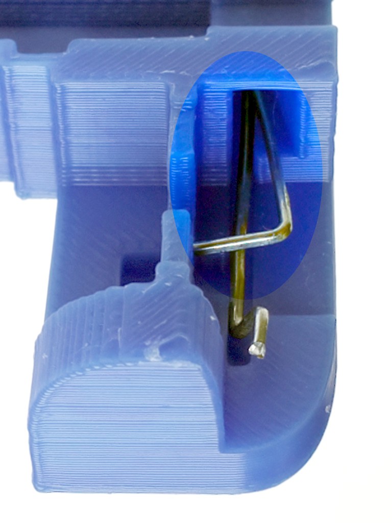
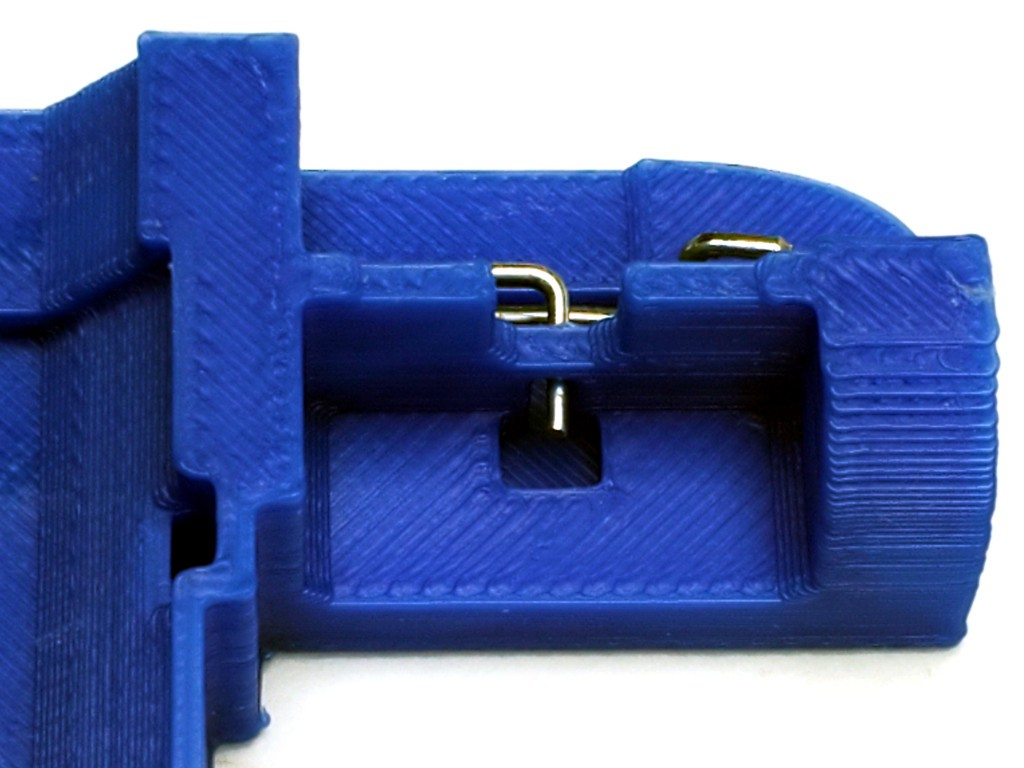
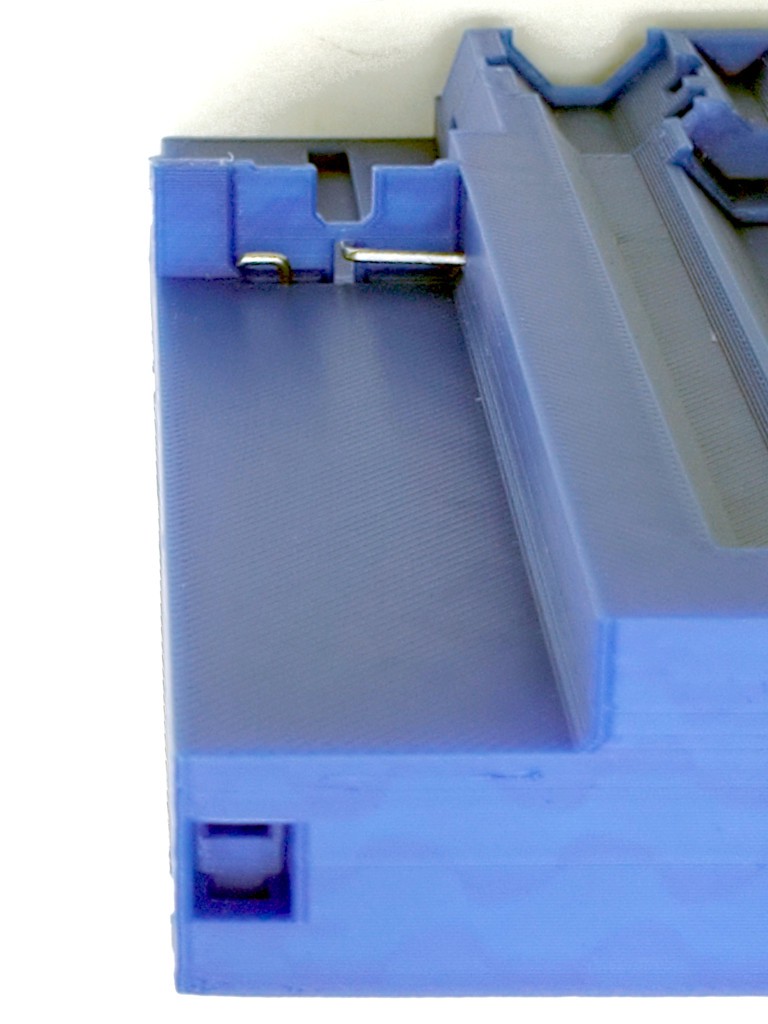
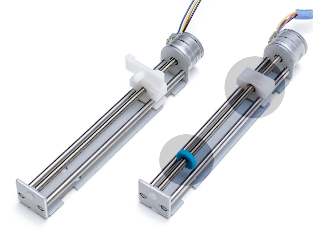
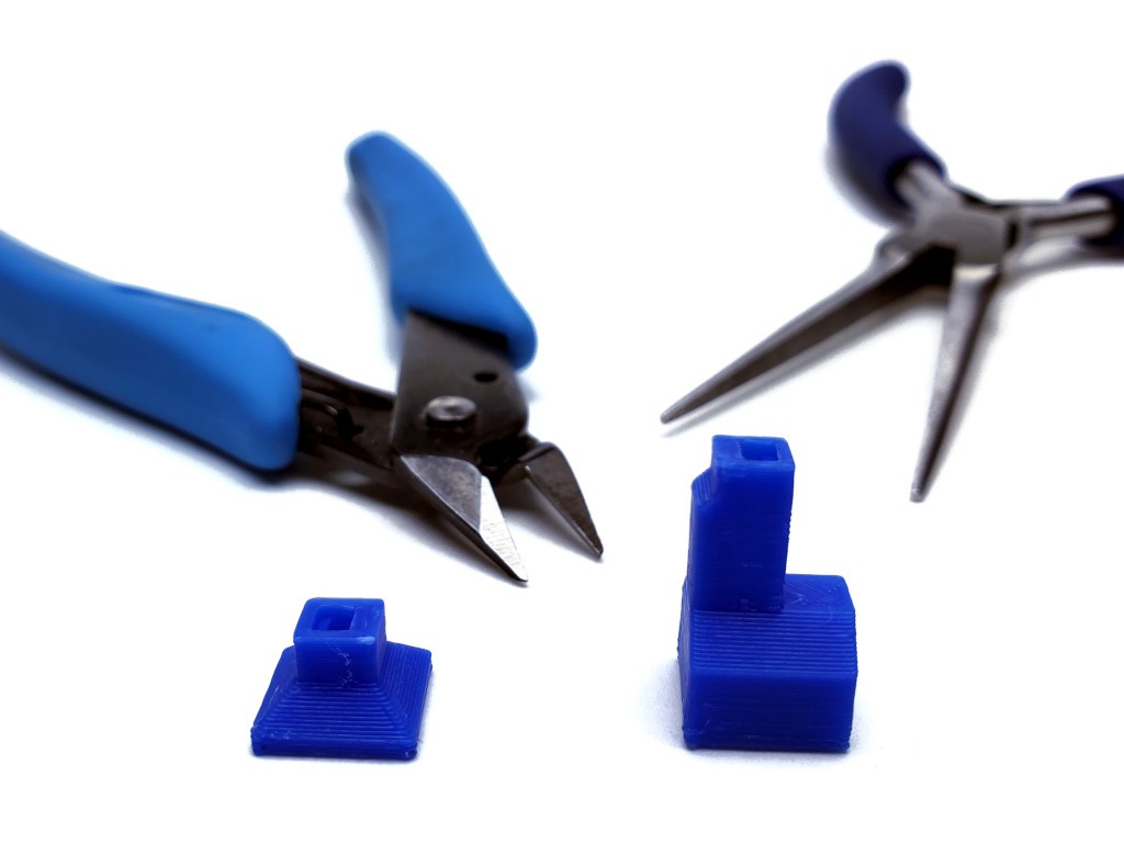
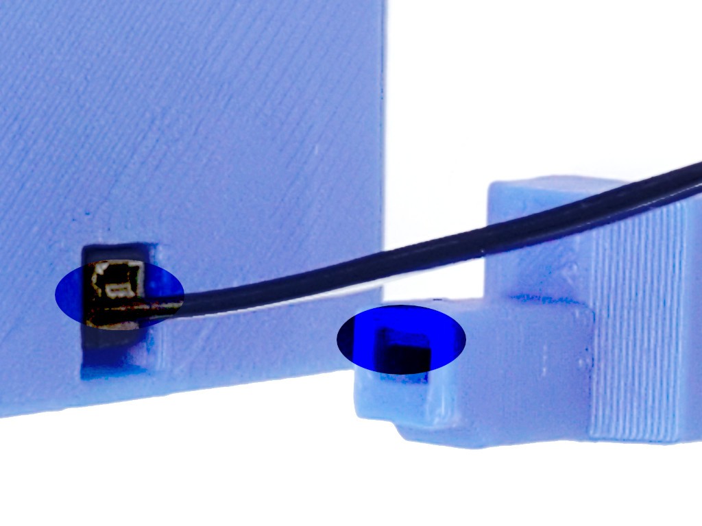
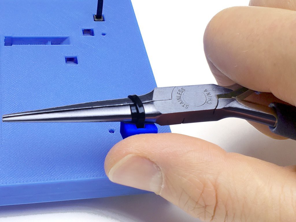
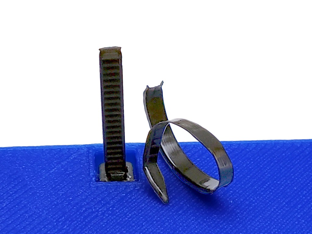
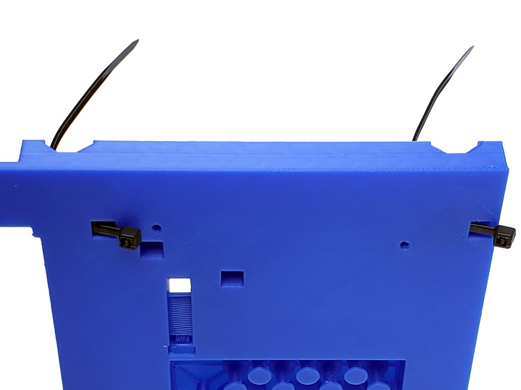
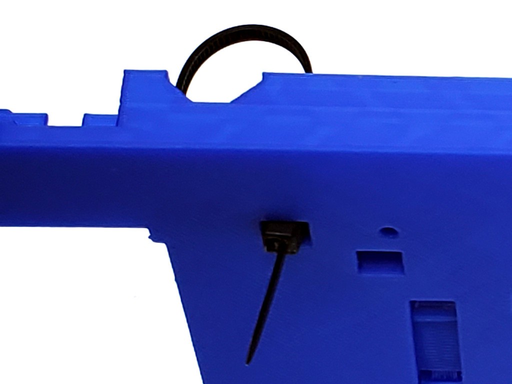
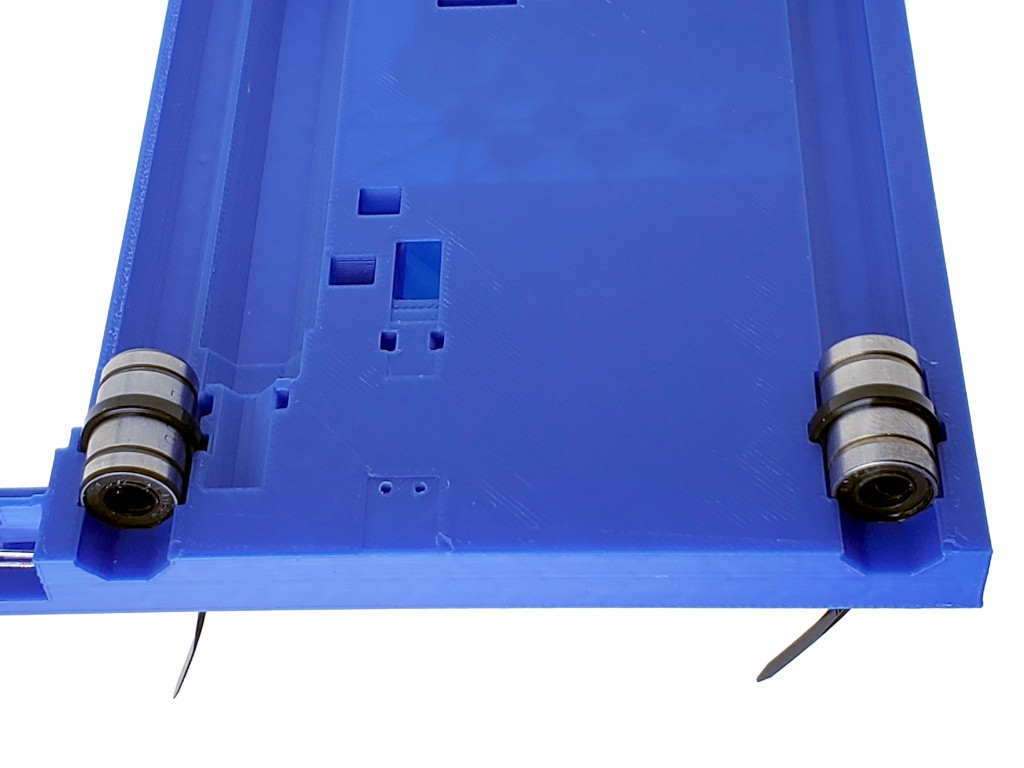
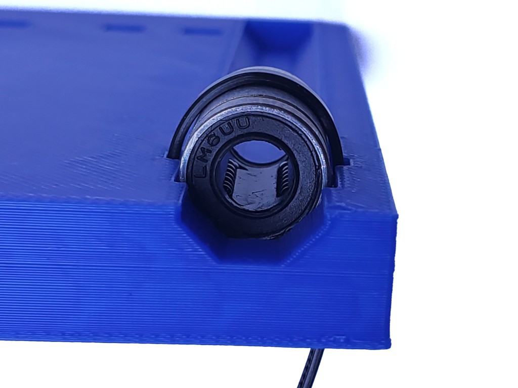
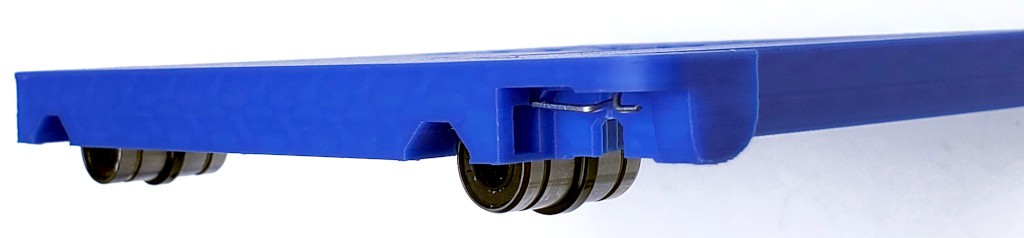
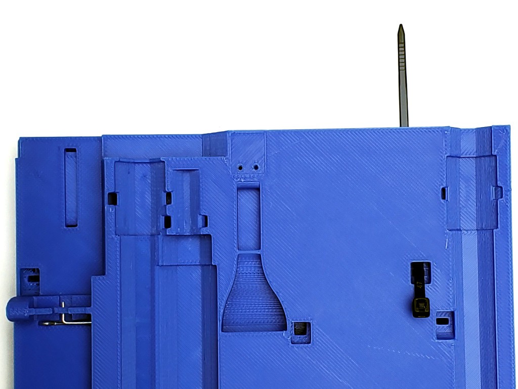
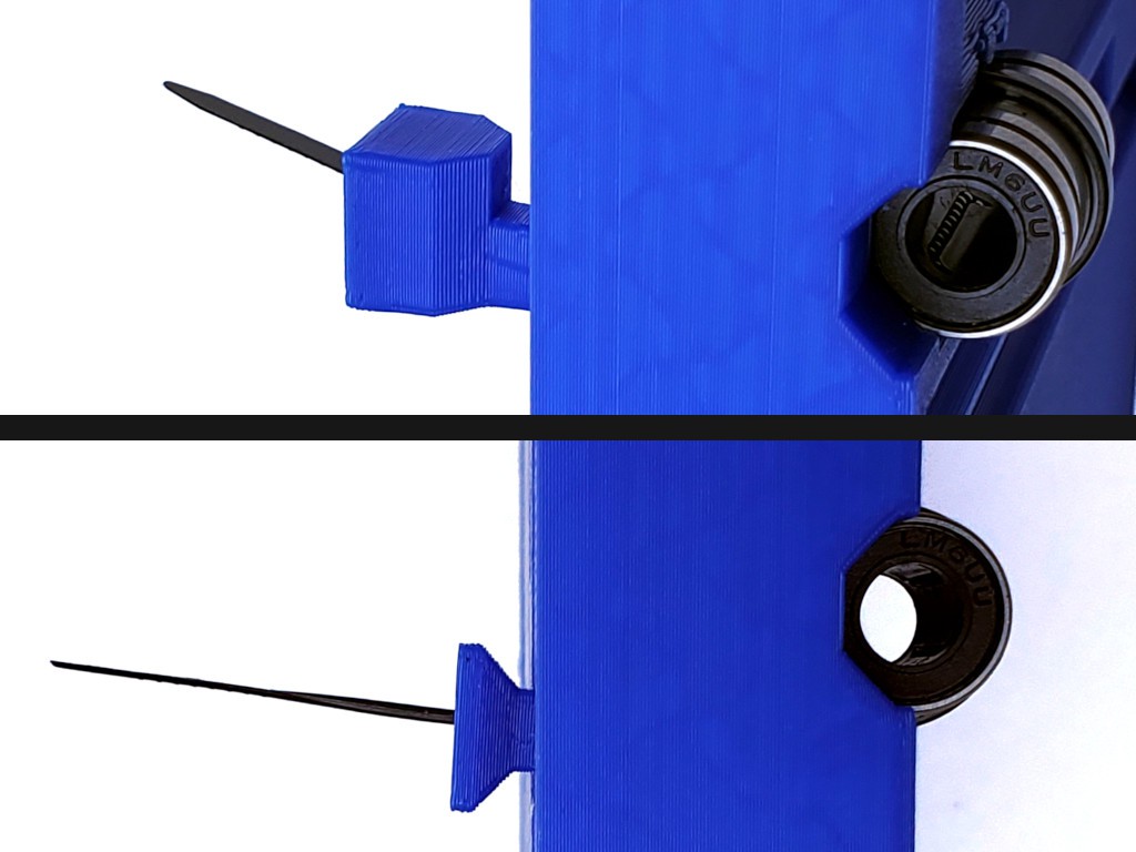
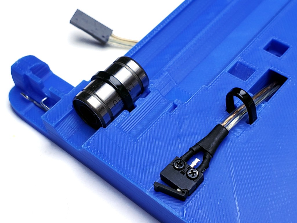
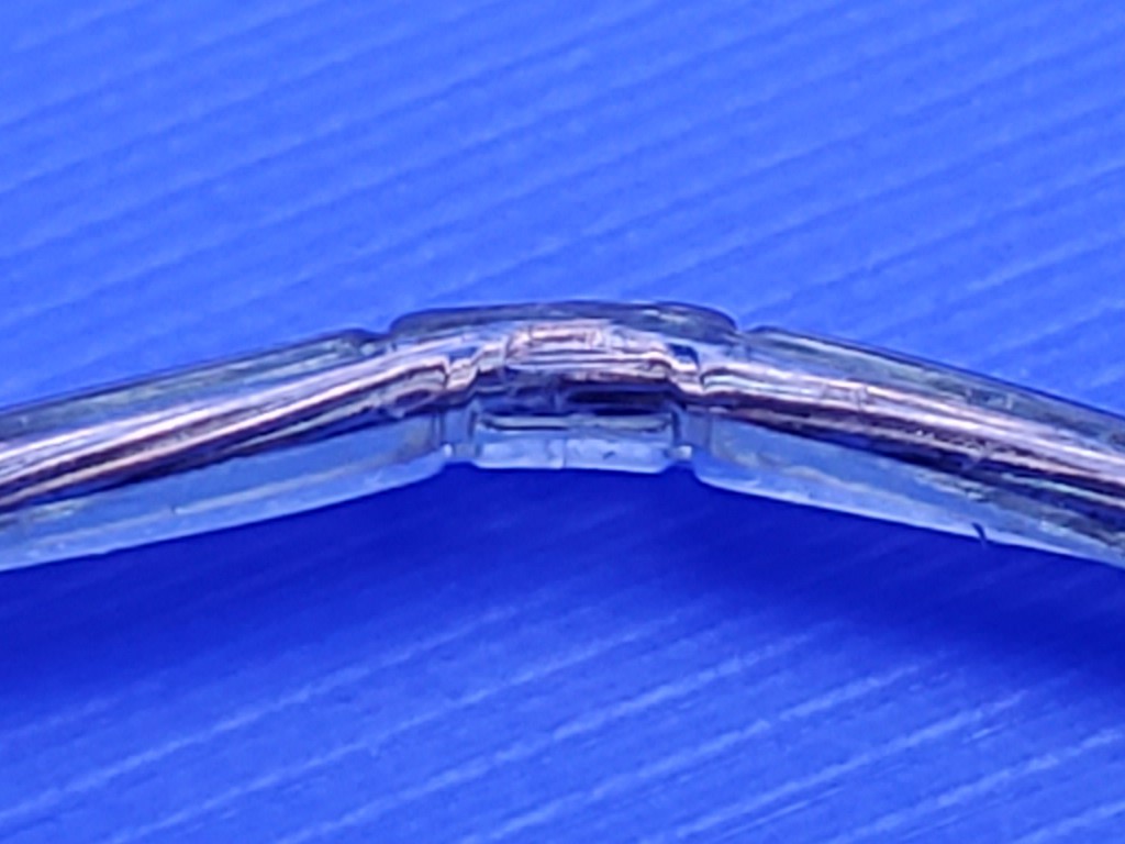
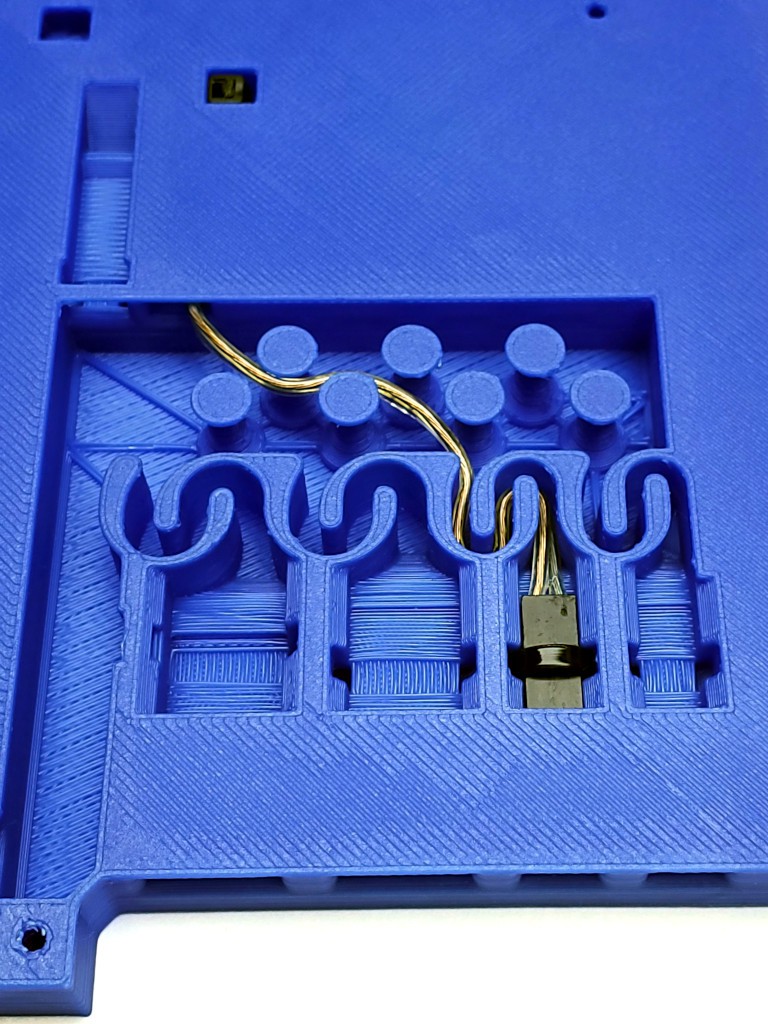
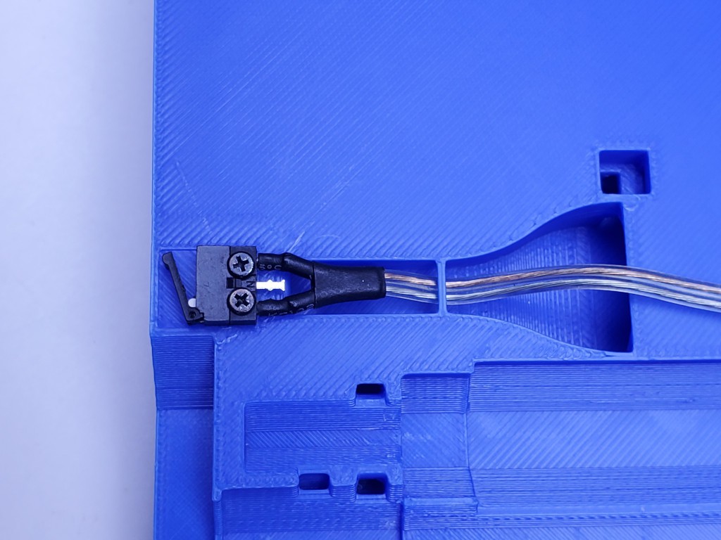
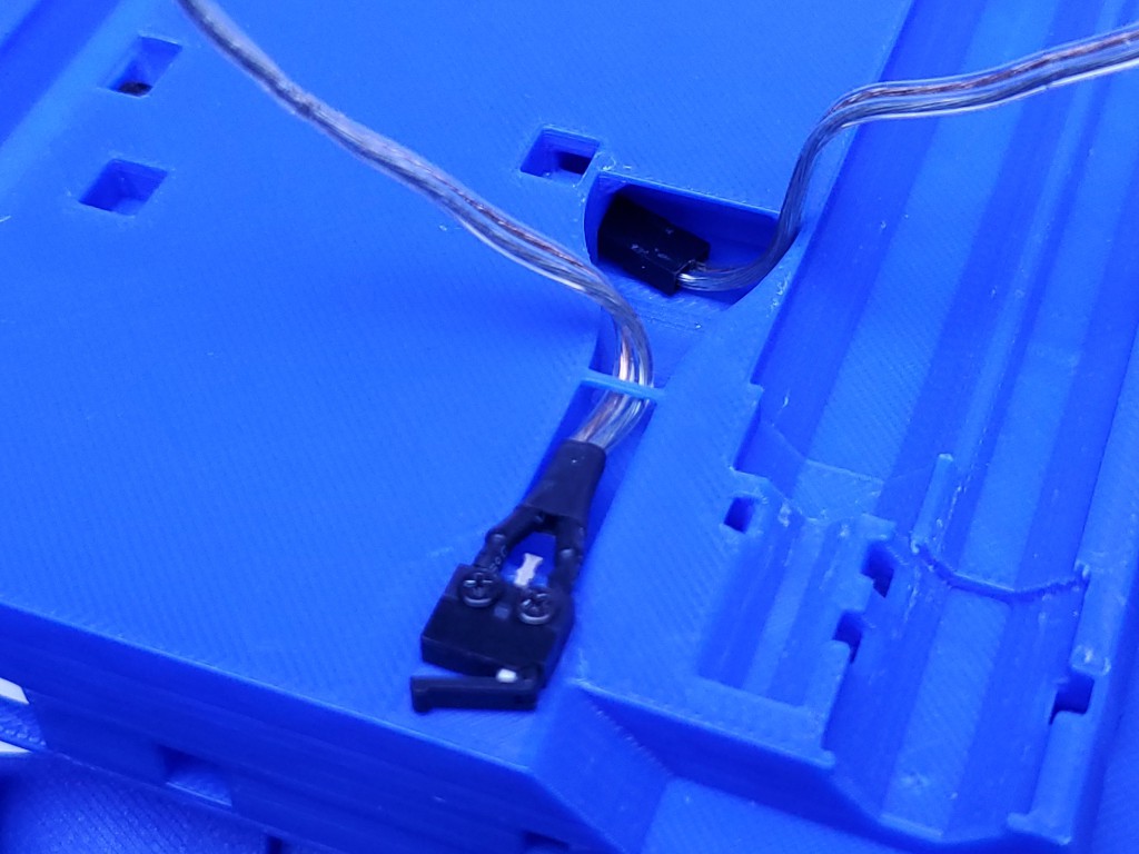
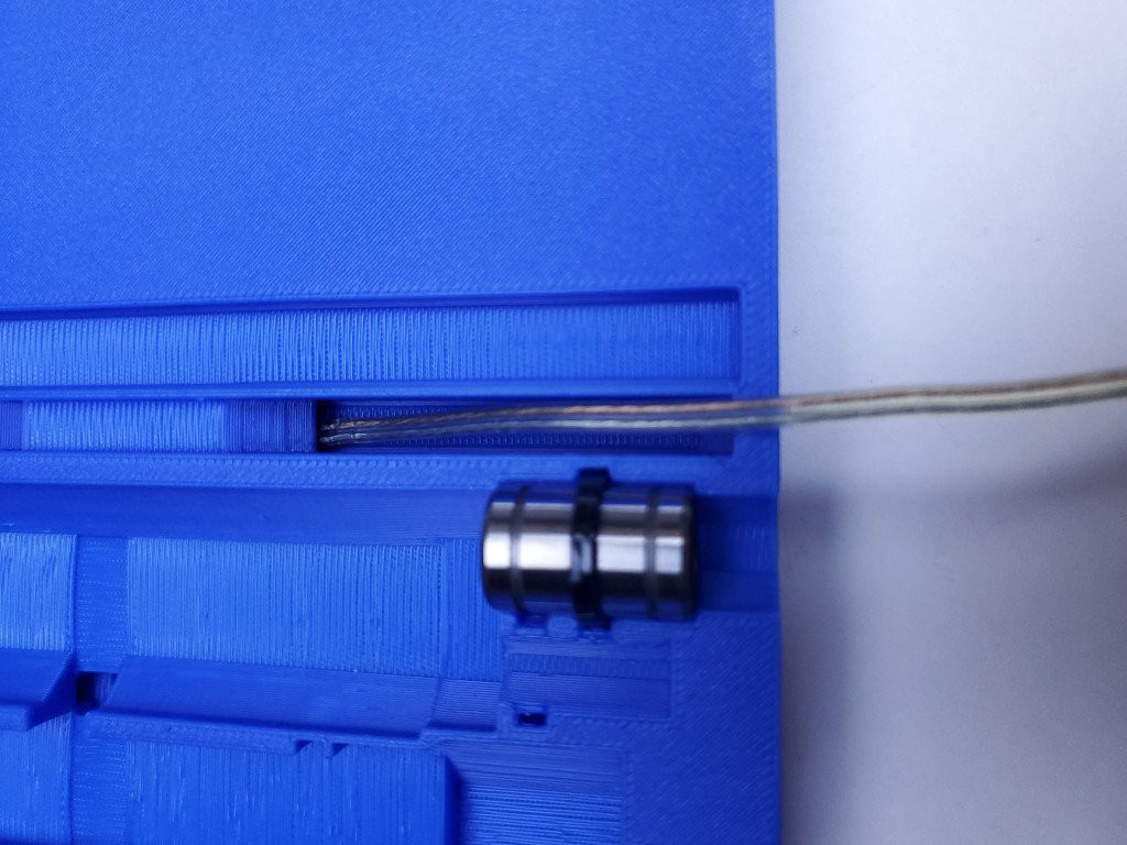
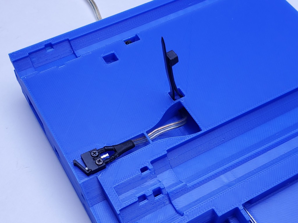
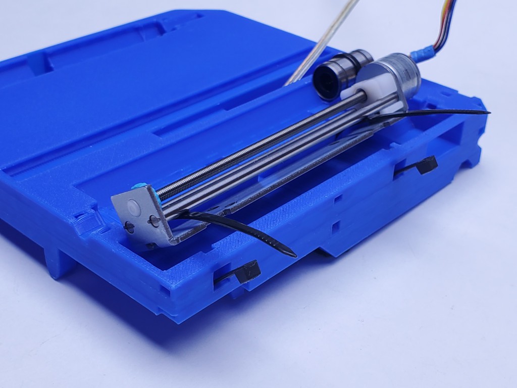
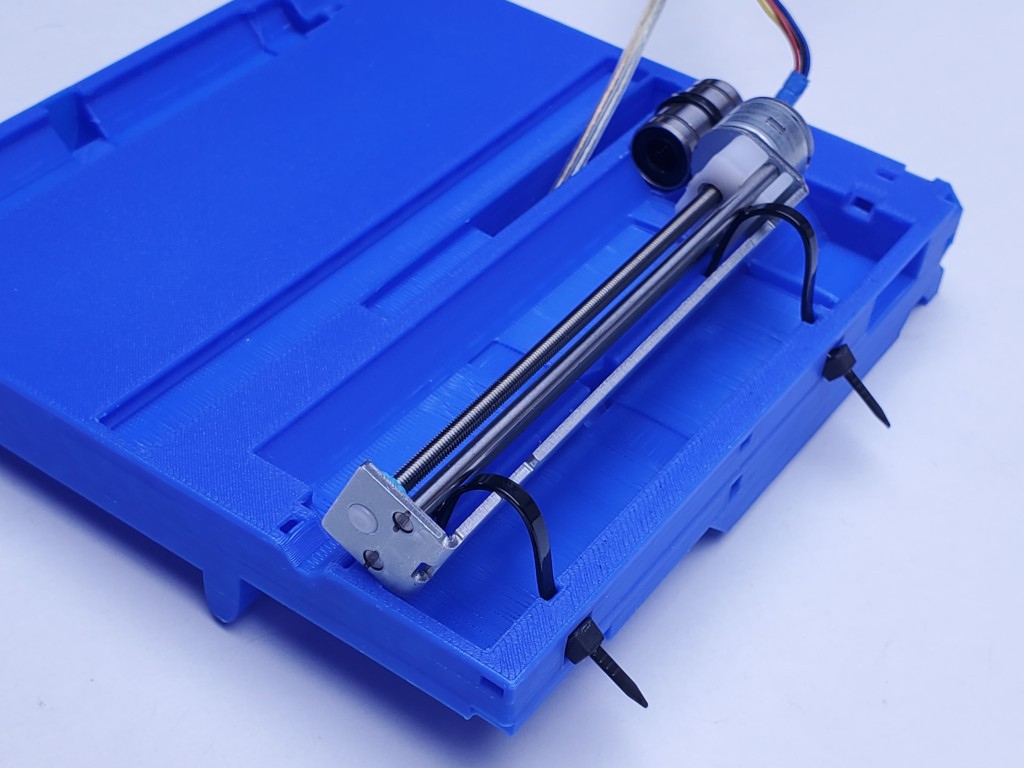
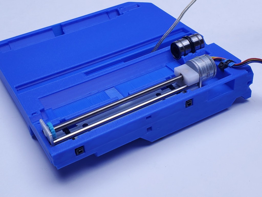
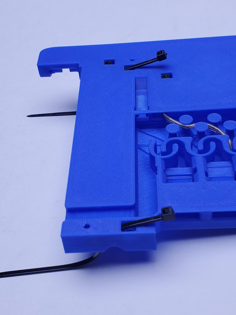
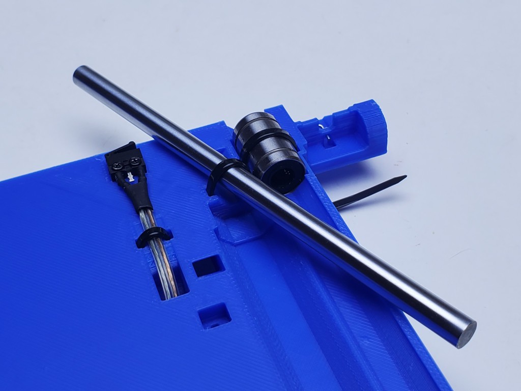
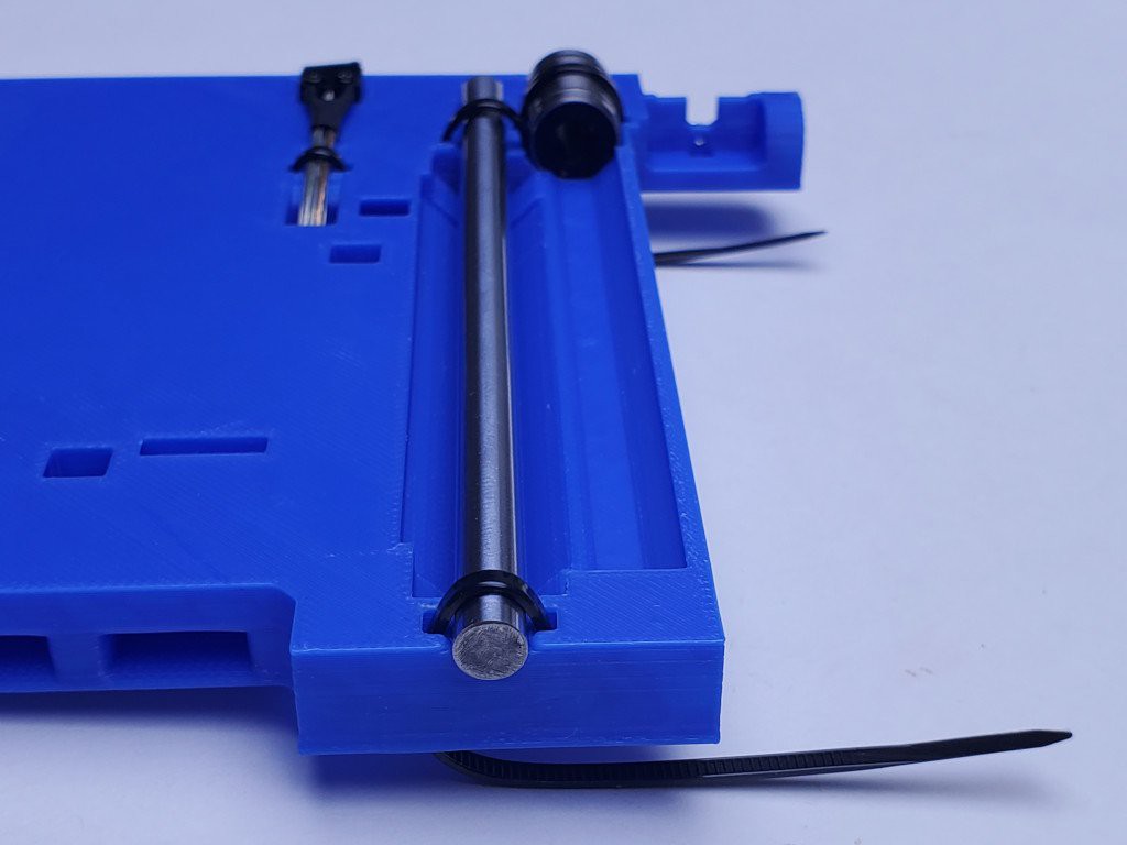
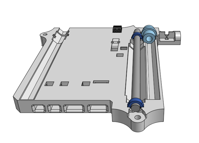
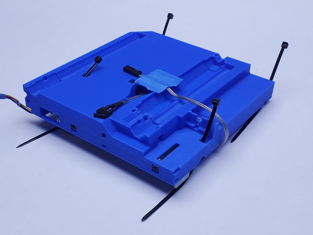
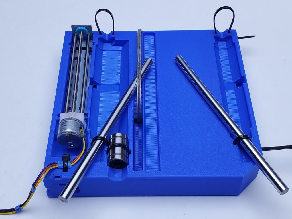
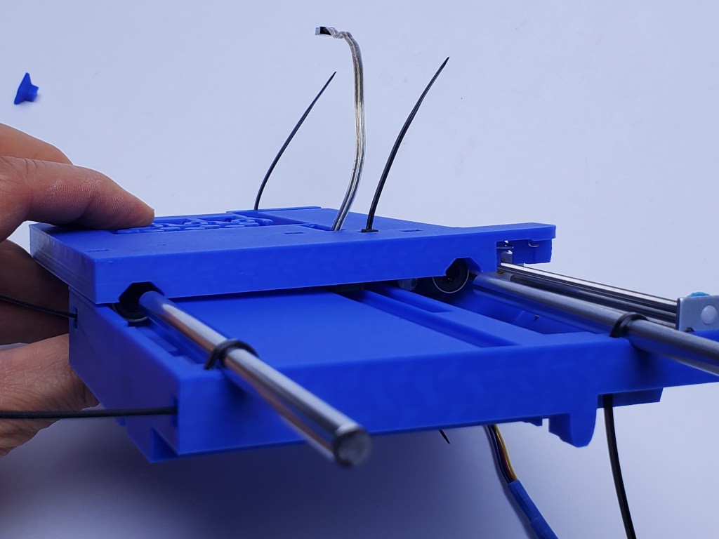
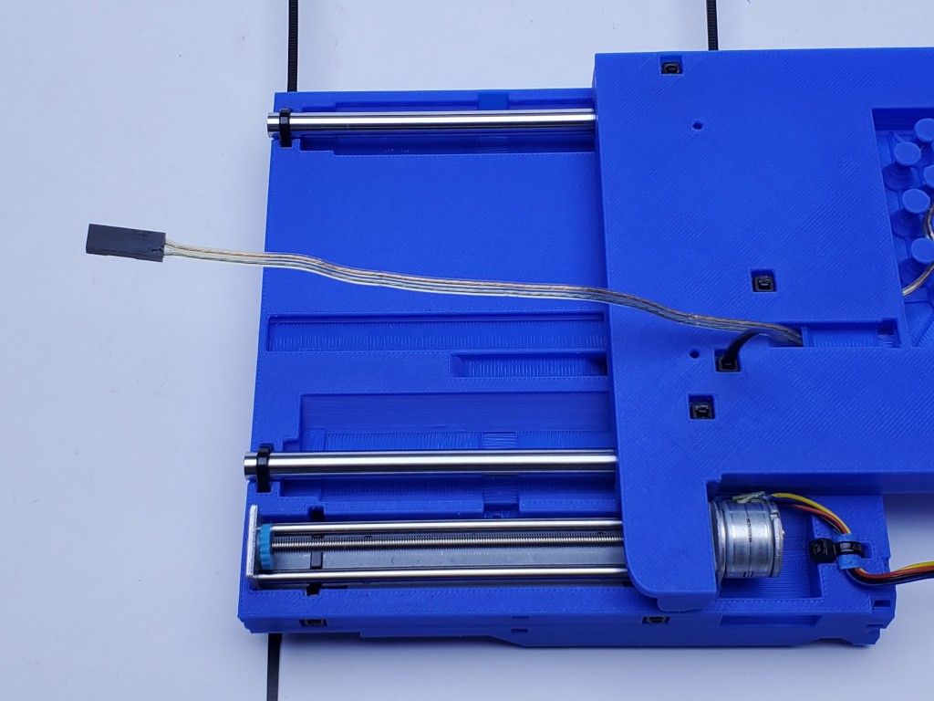
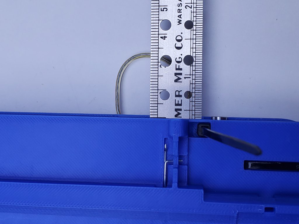
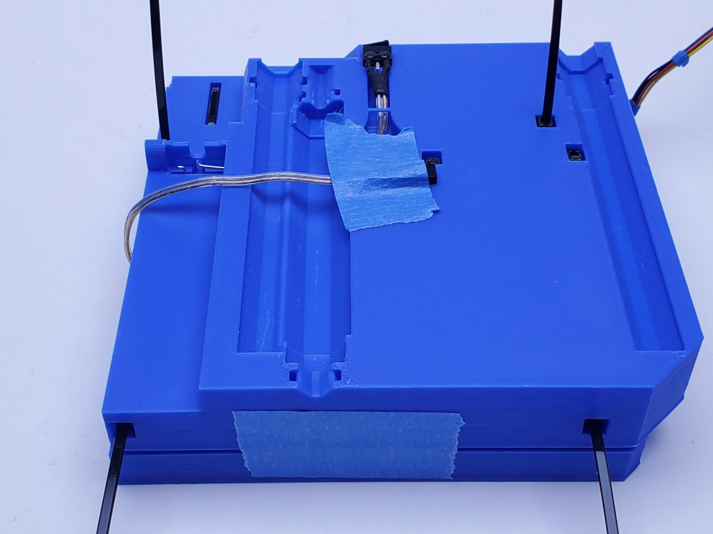
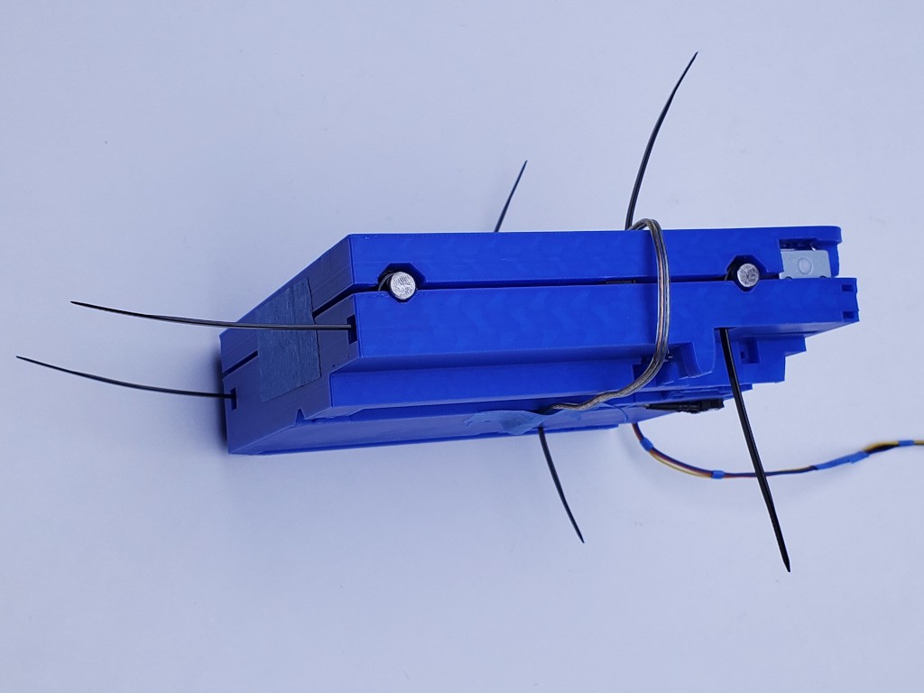
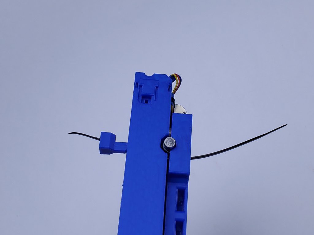
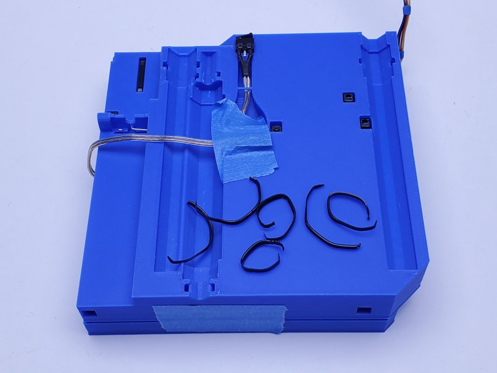
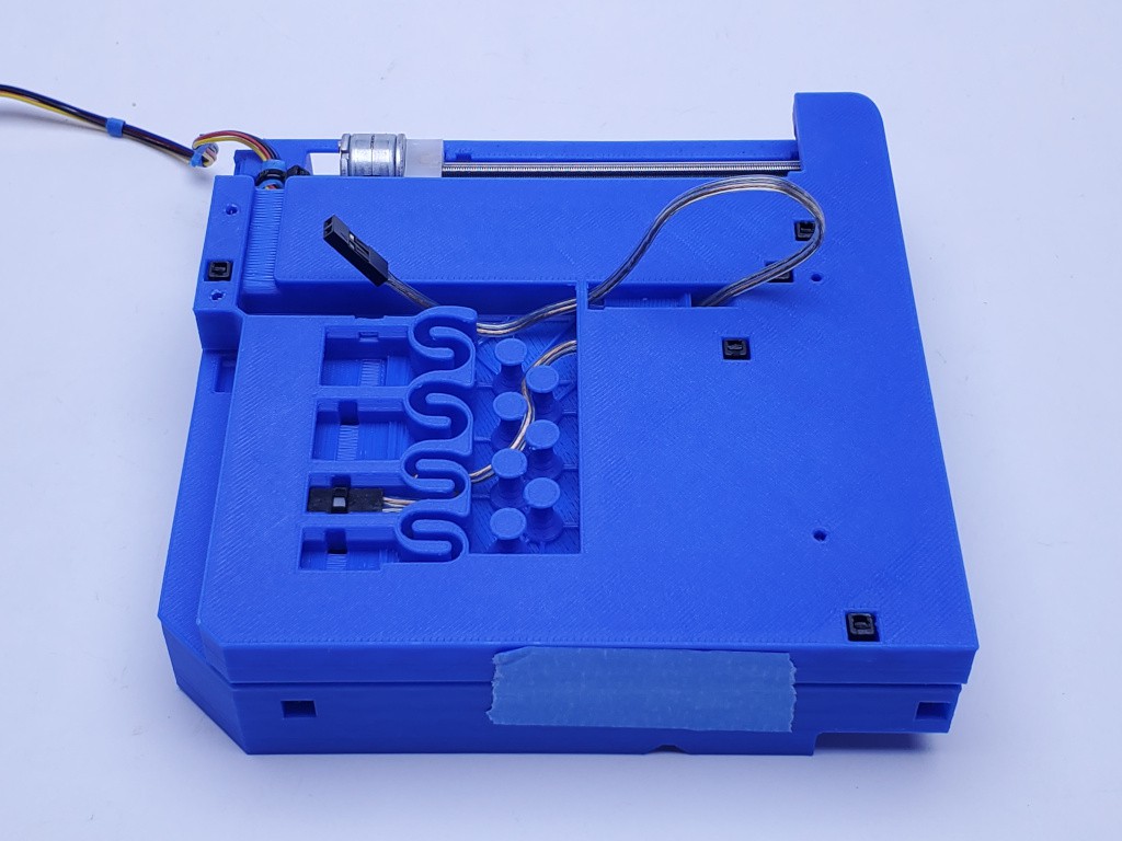
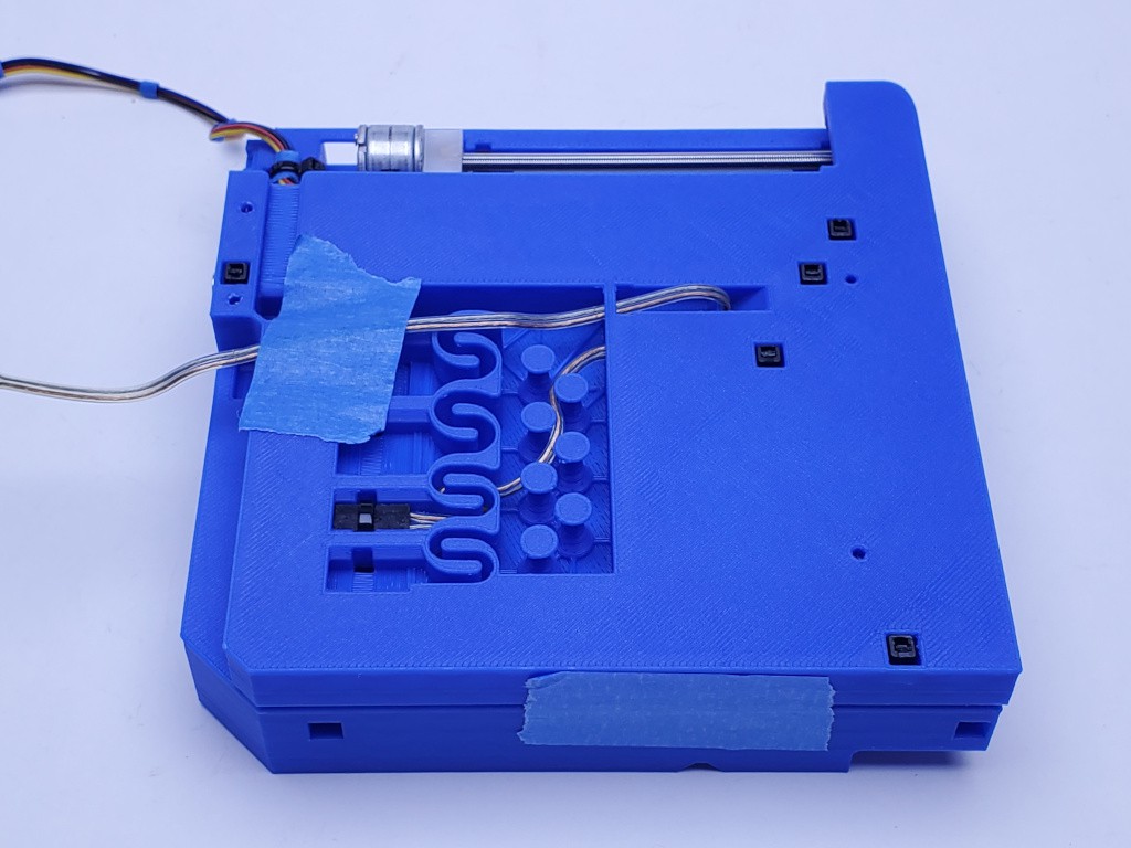
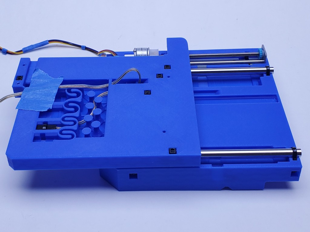
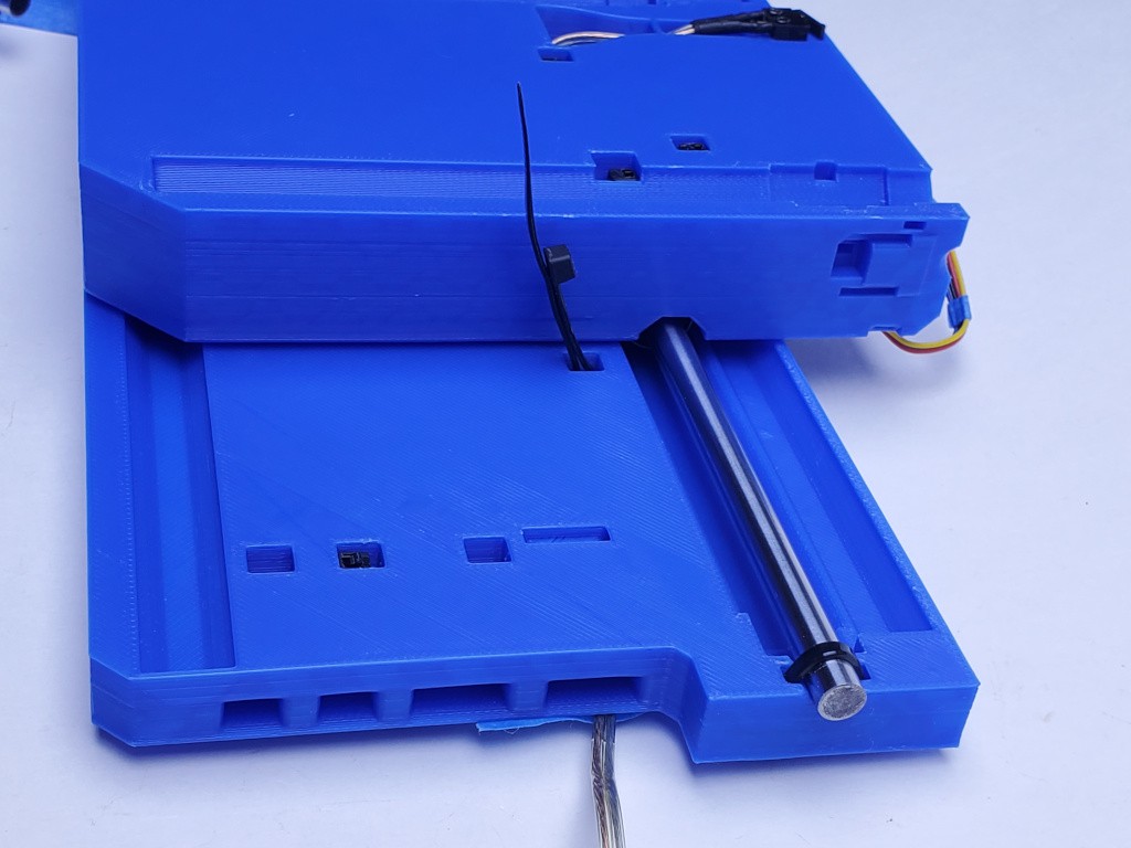
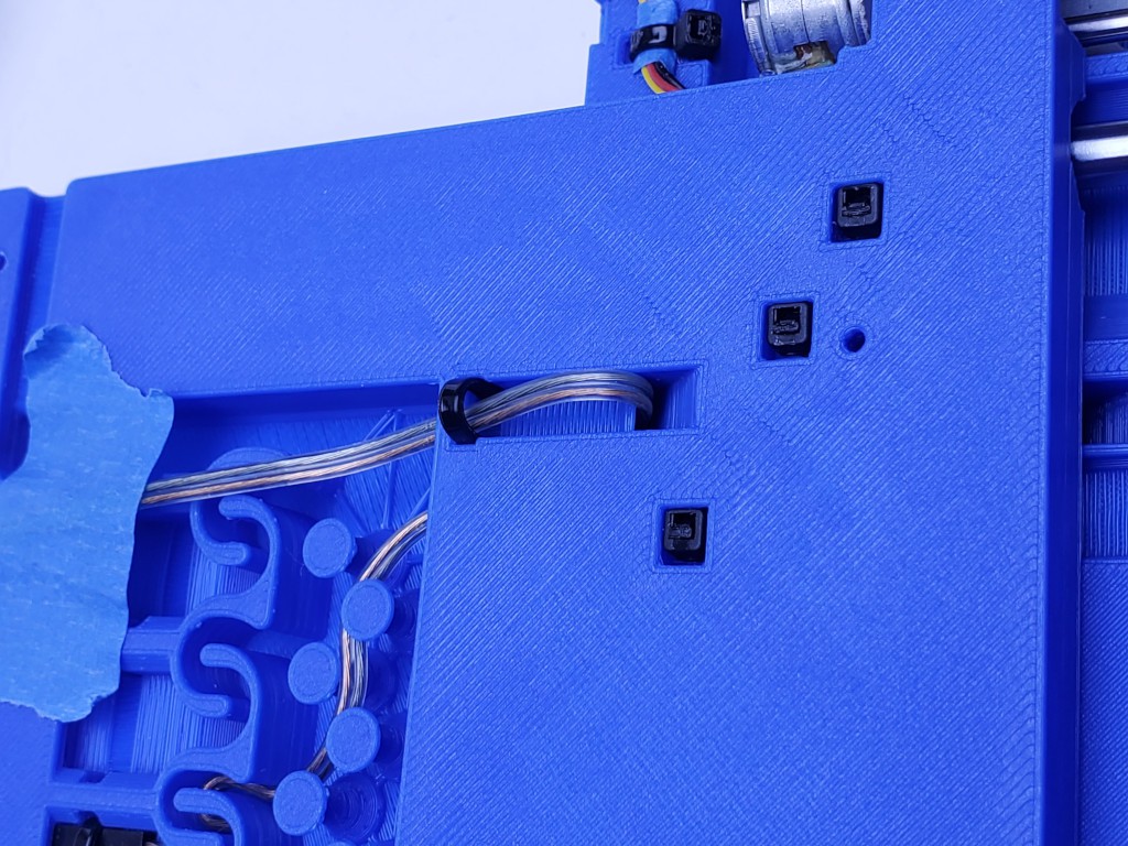
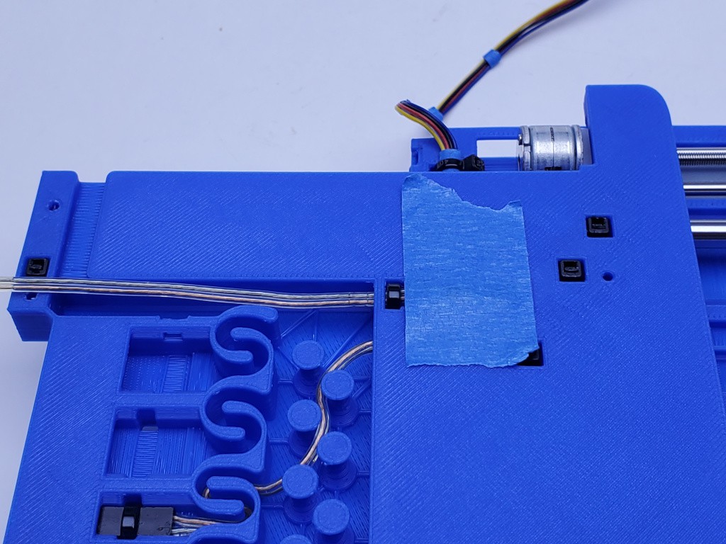
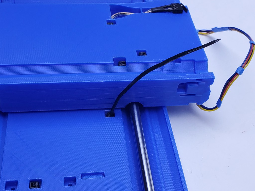
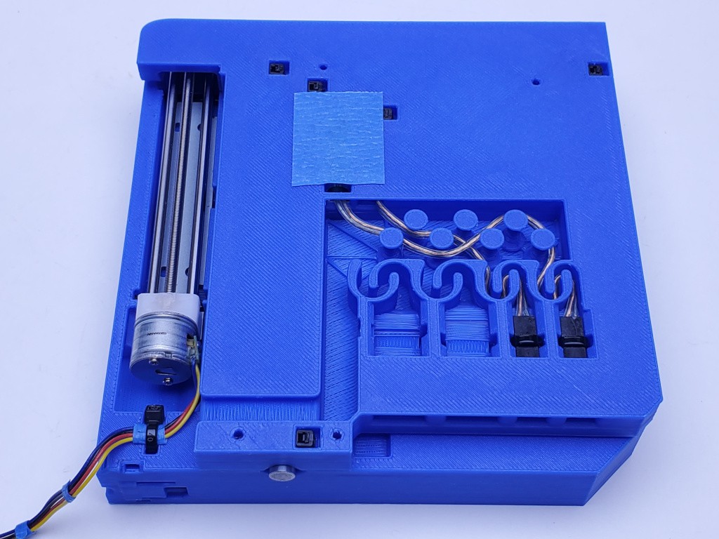
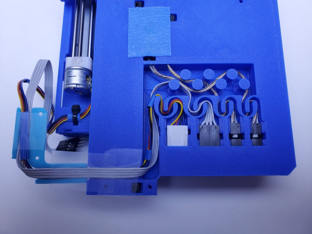
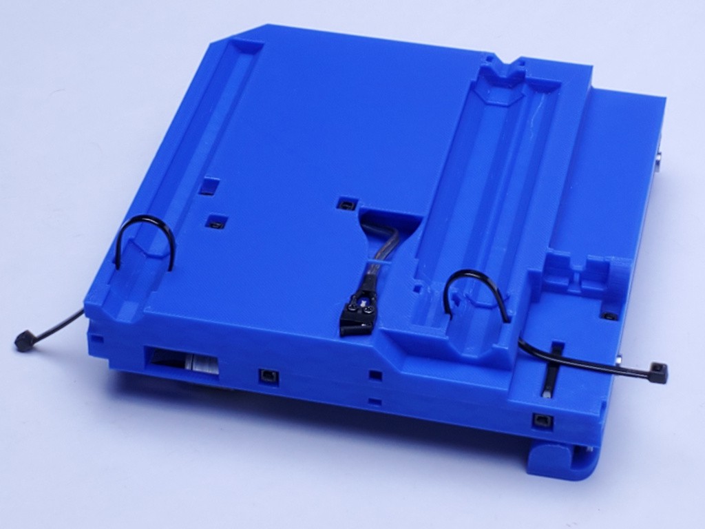
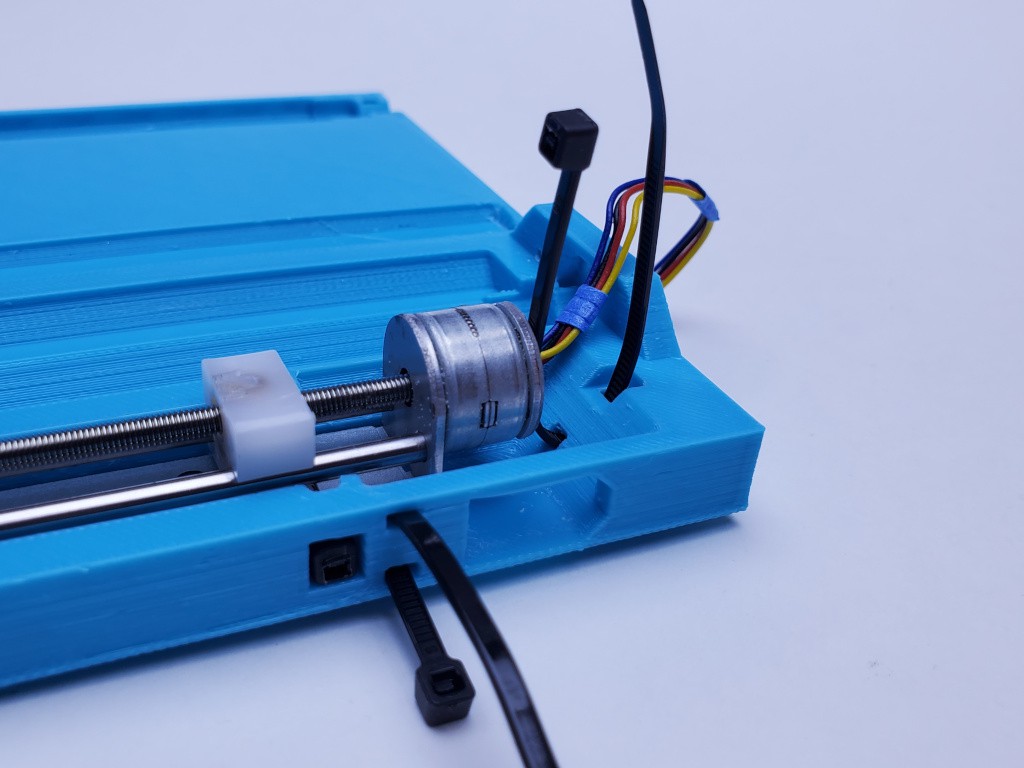
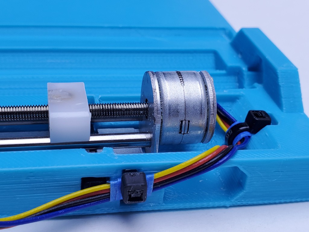
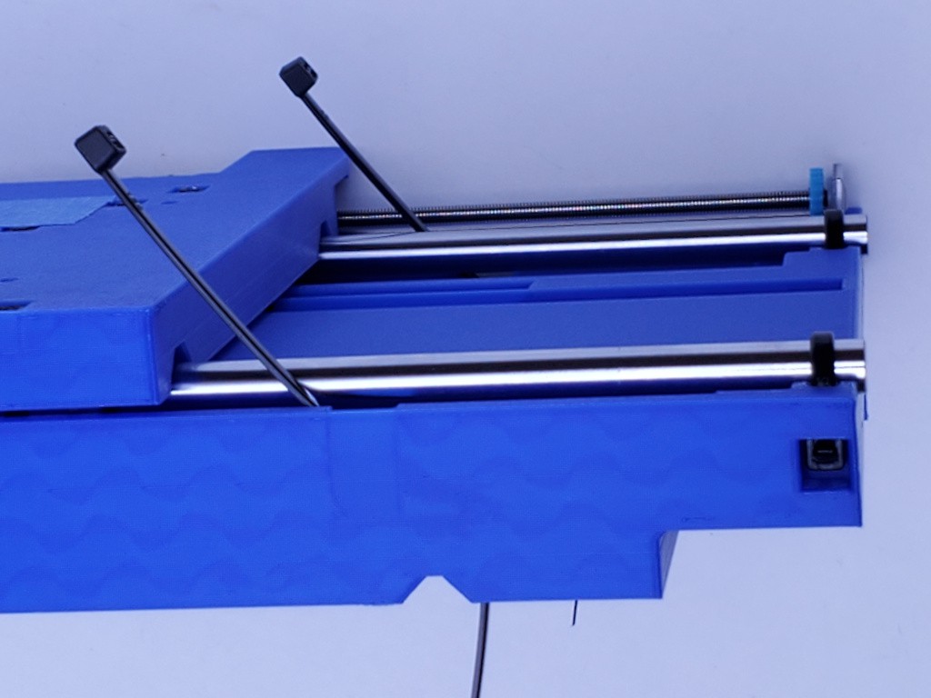
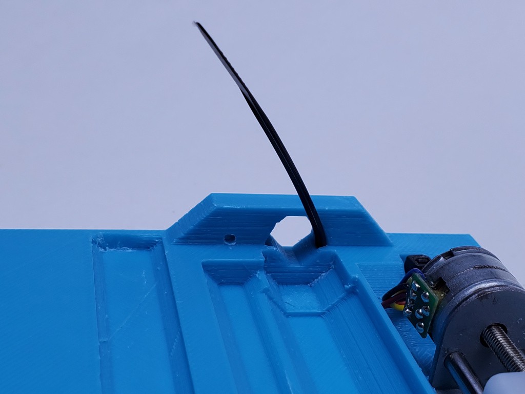
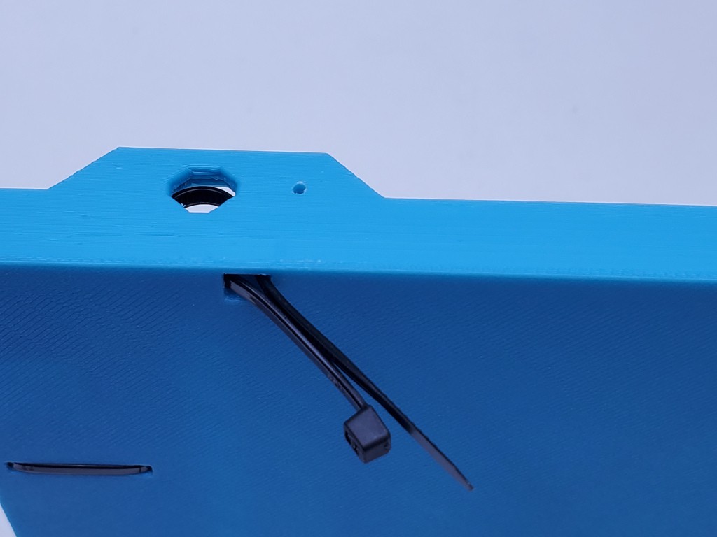
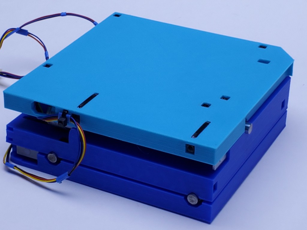
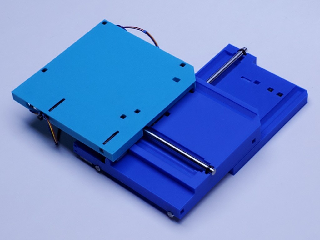
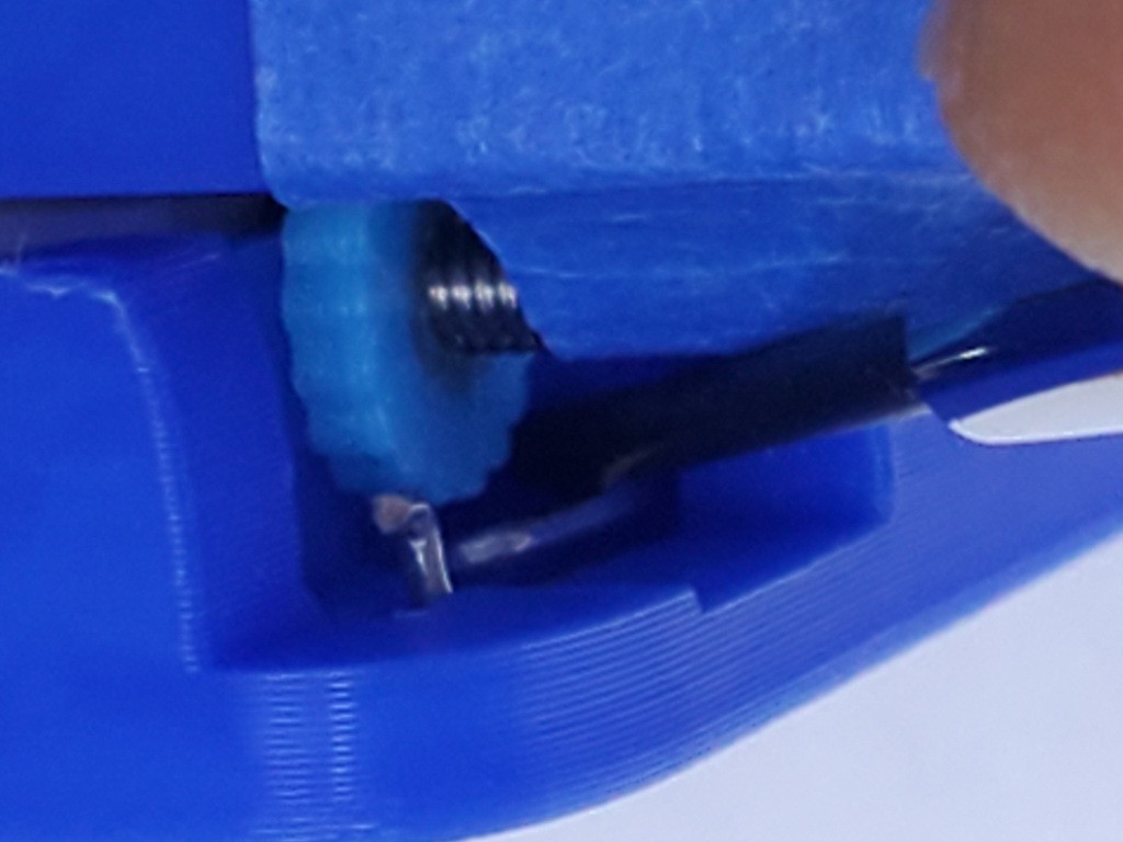
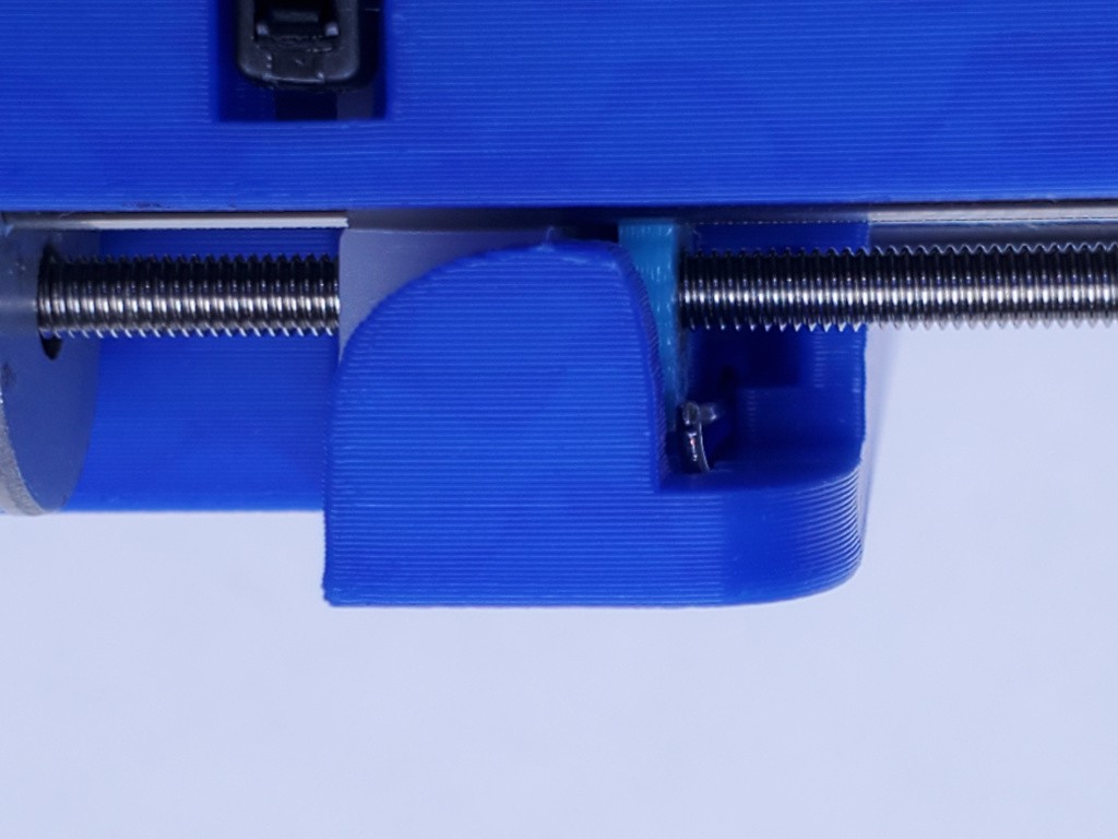
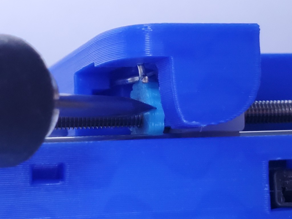
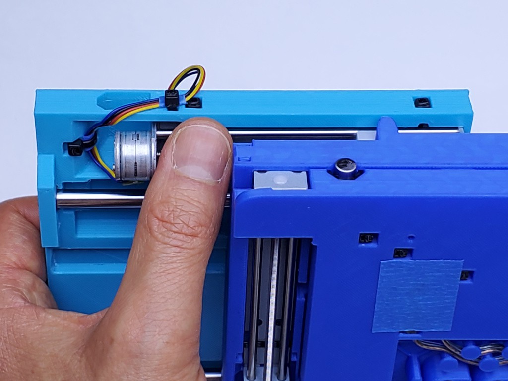
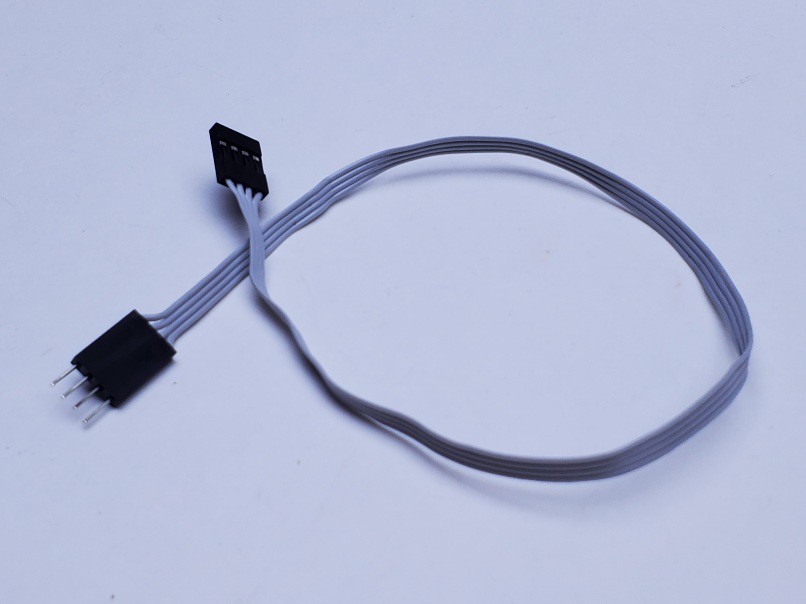
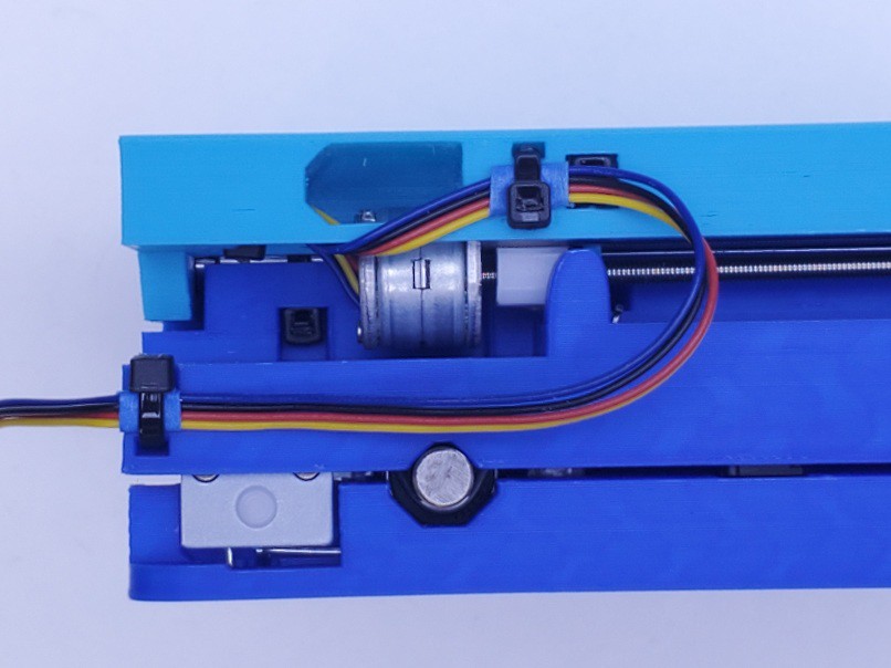
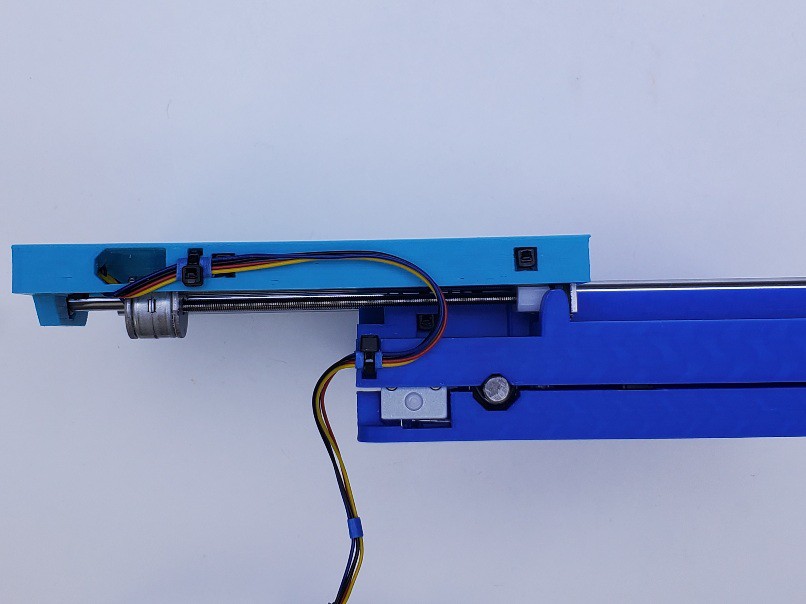
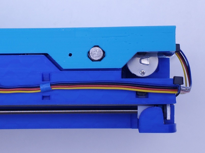
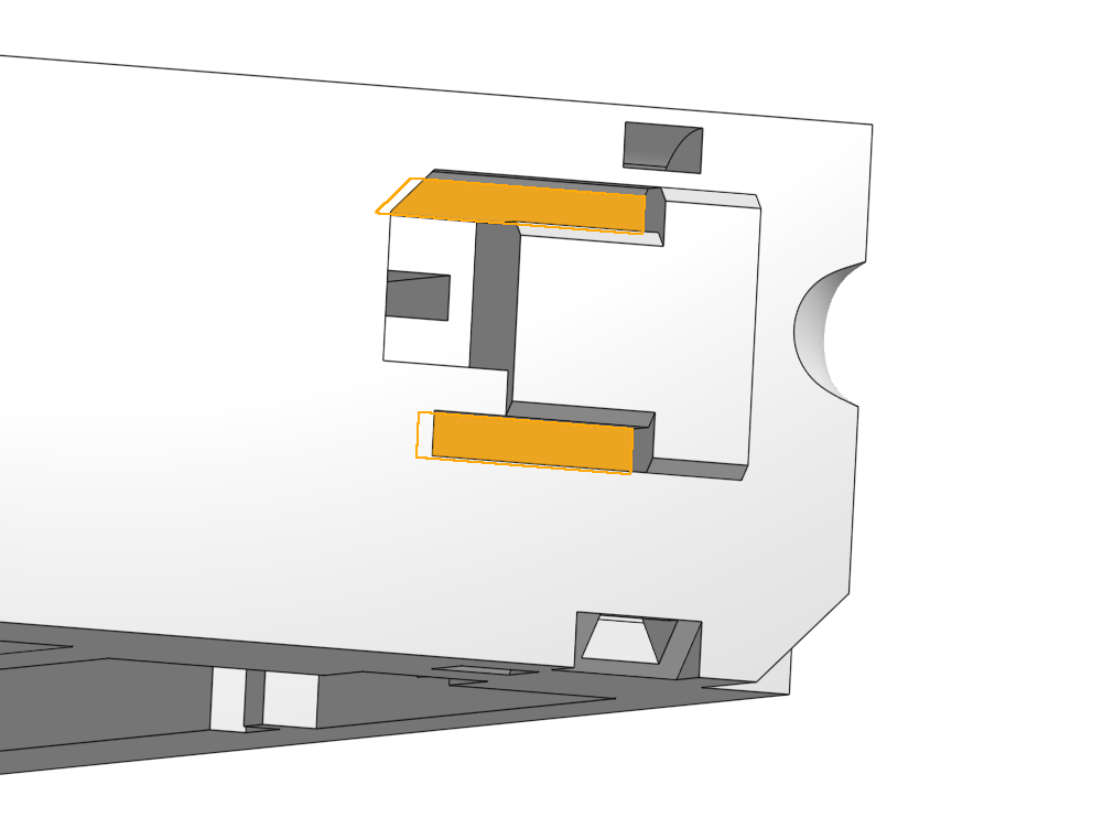
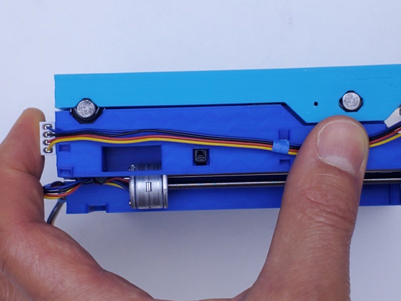
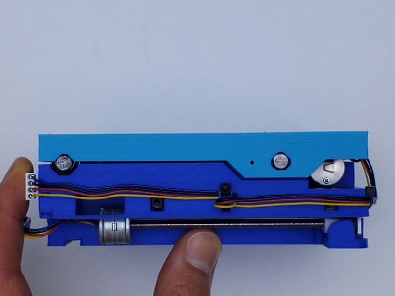
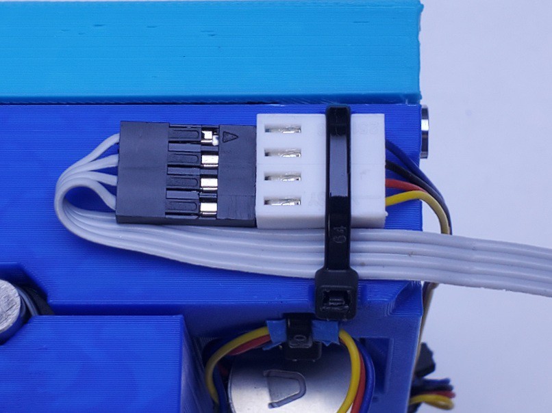
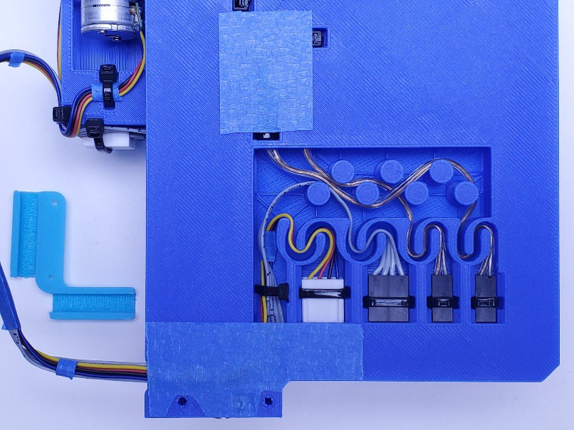 For convenient handling, a neatly placed piece of tape holds the wires in the channel. In this pic, I left a little extra tail on the Y connector zip tie which also helps to keep the wires up in the channel. Just opportunistic; not necessary.
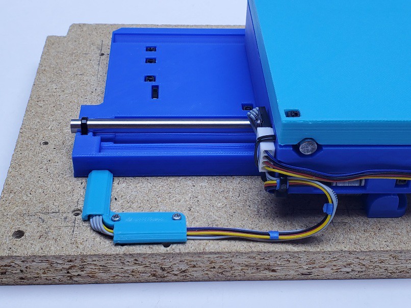
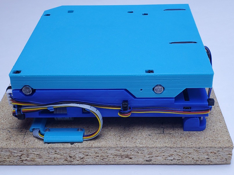
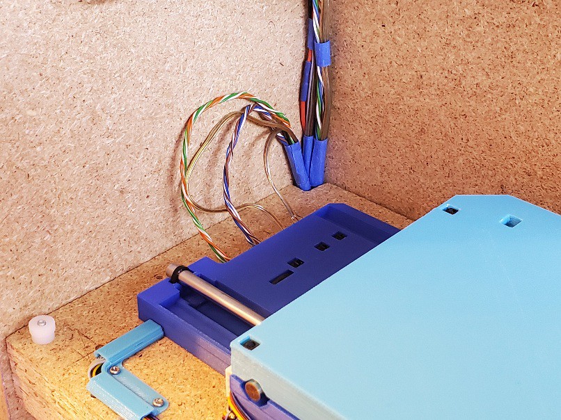
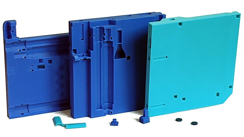
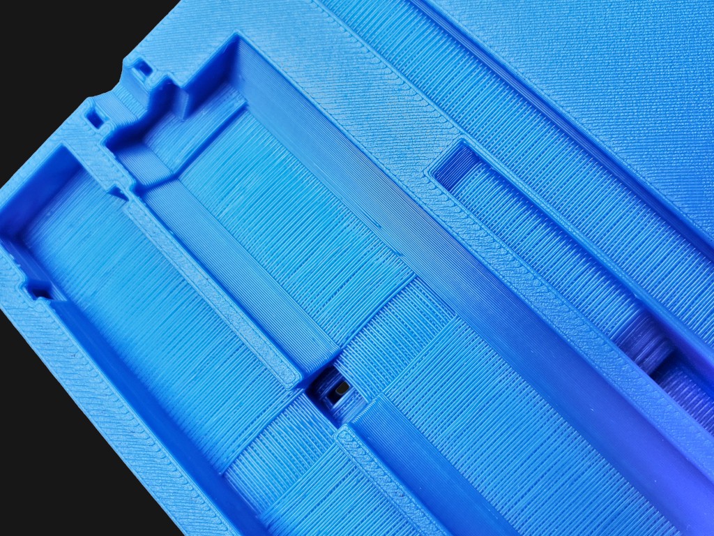
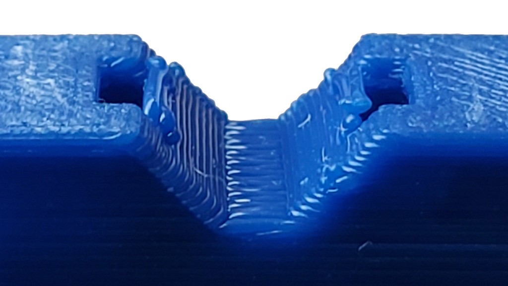


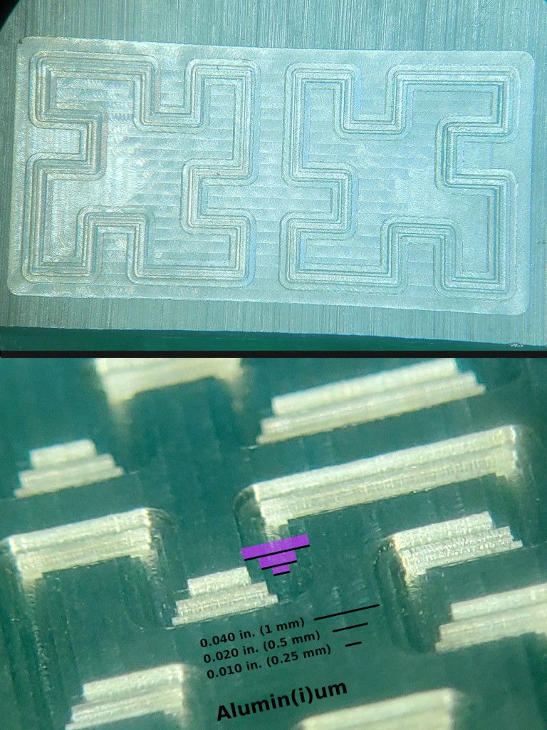
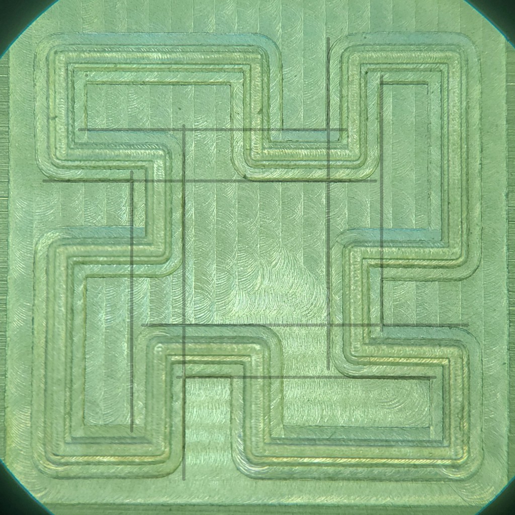

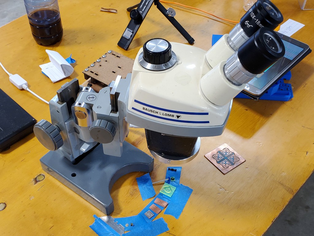
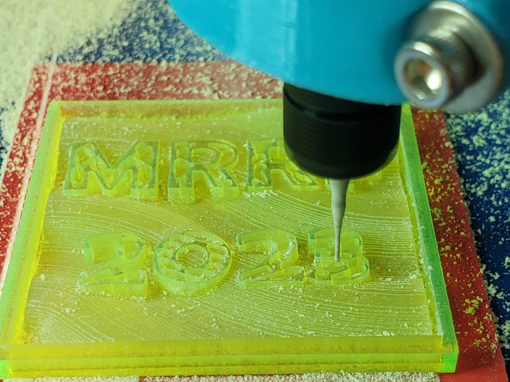


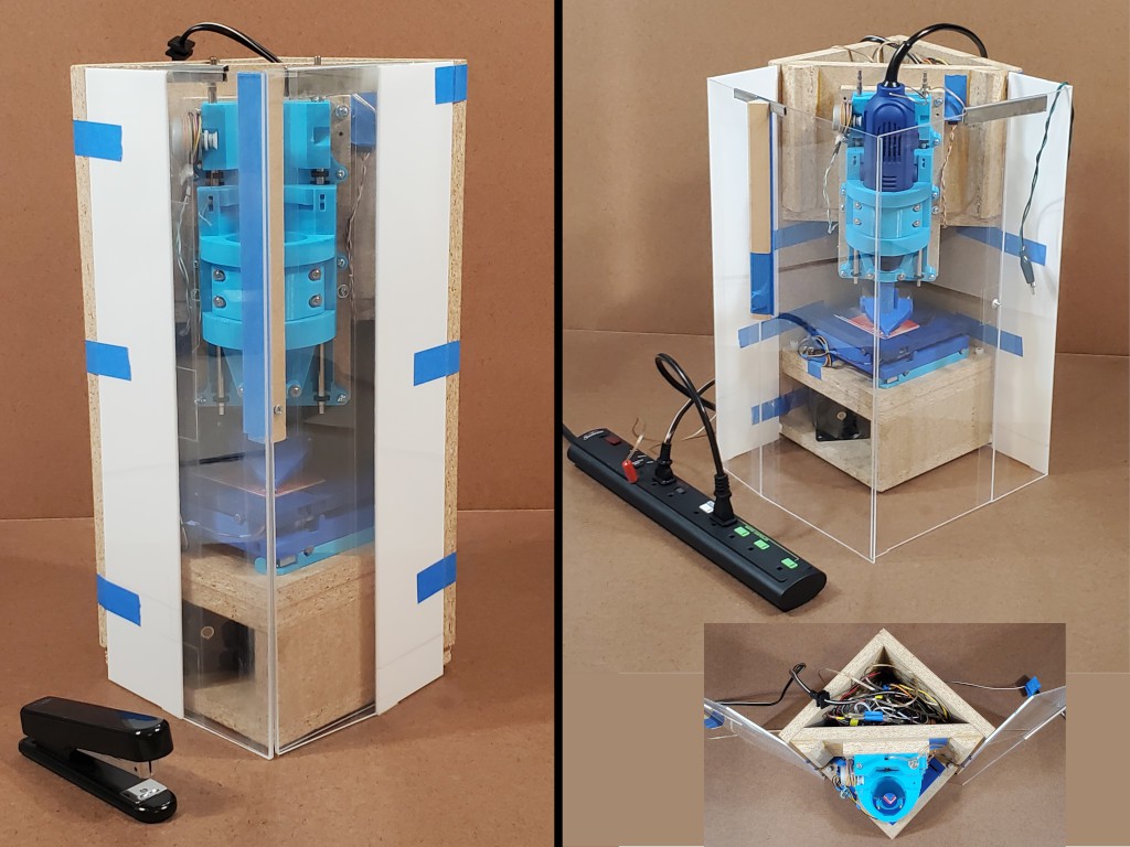
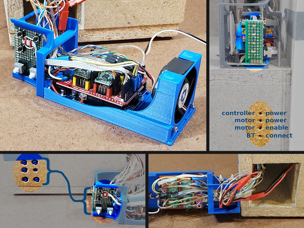
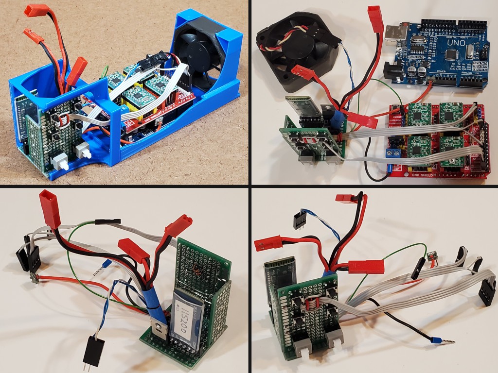
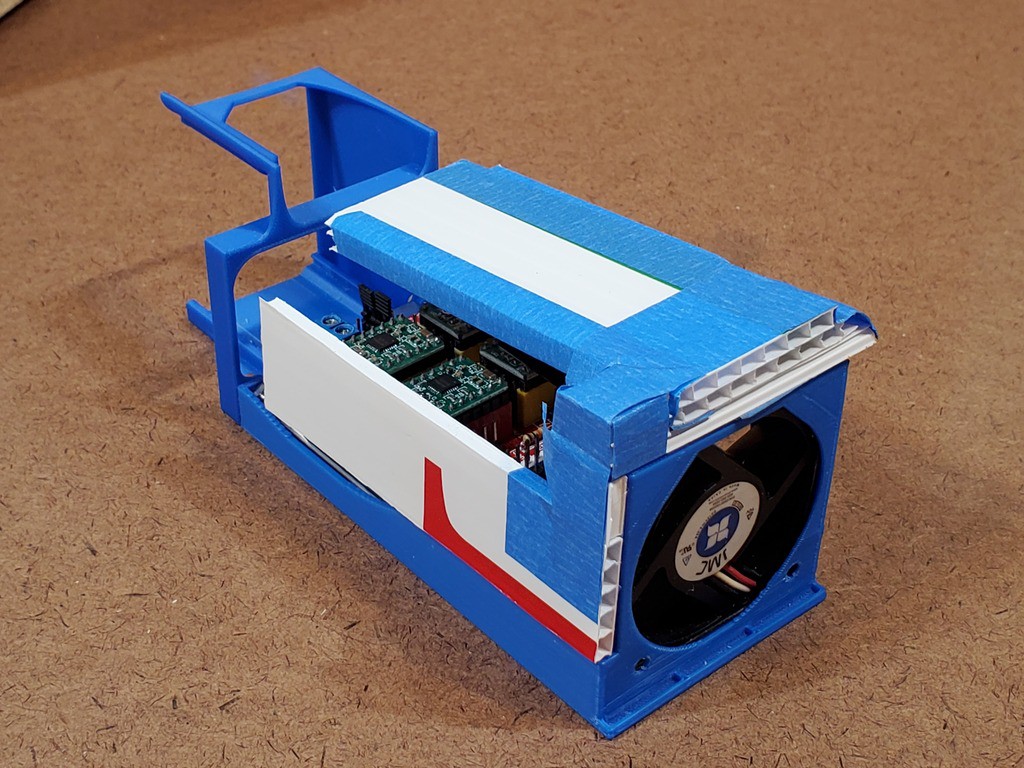
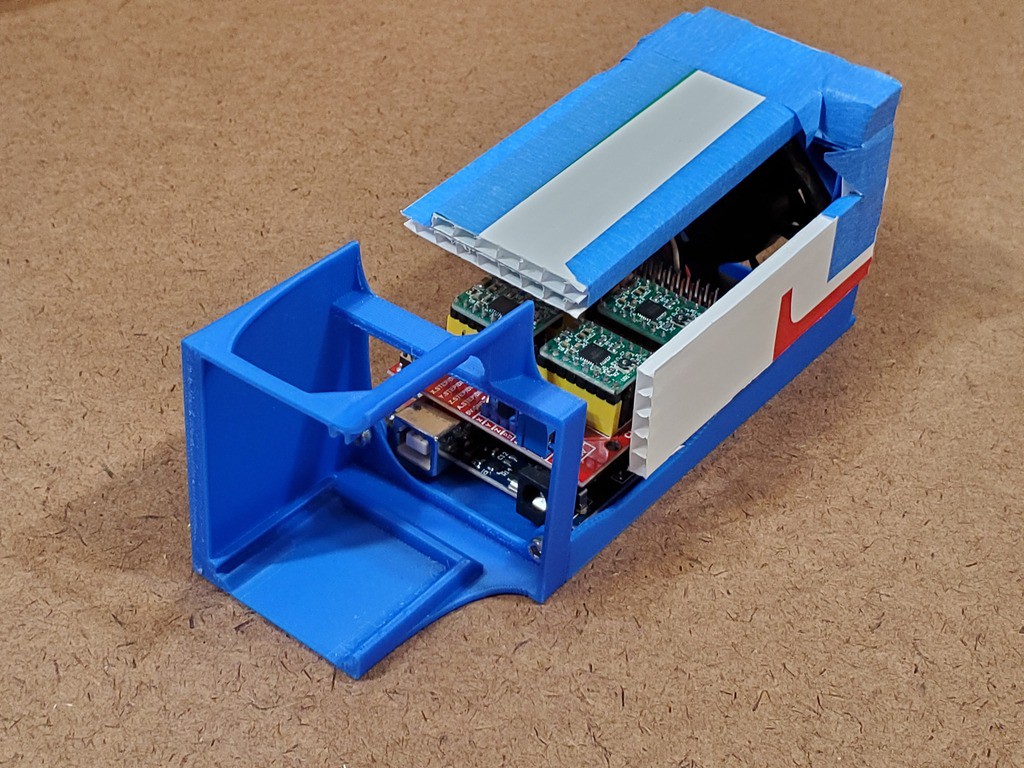
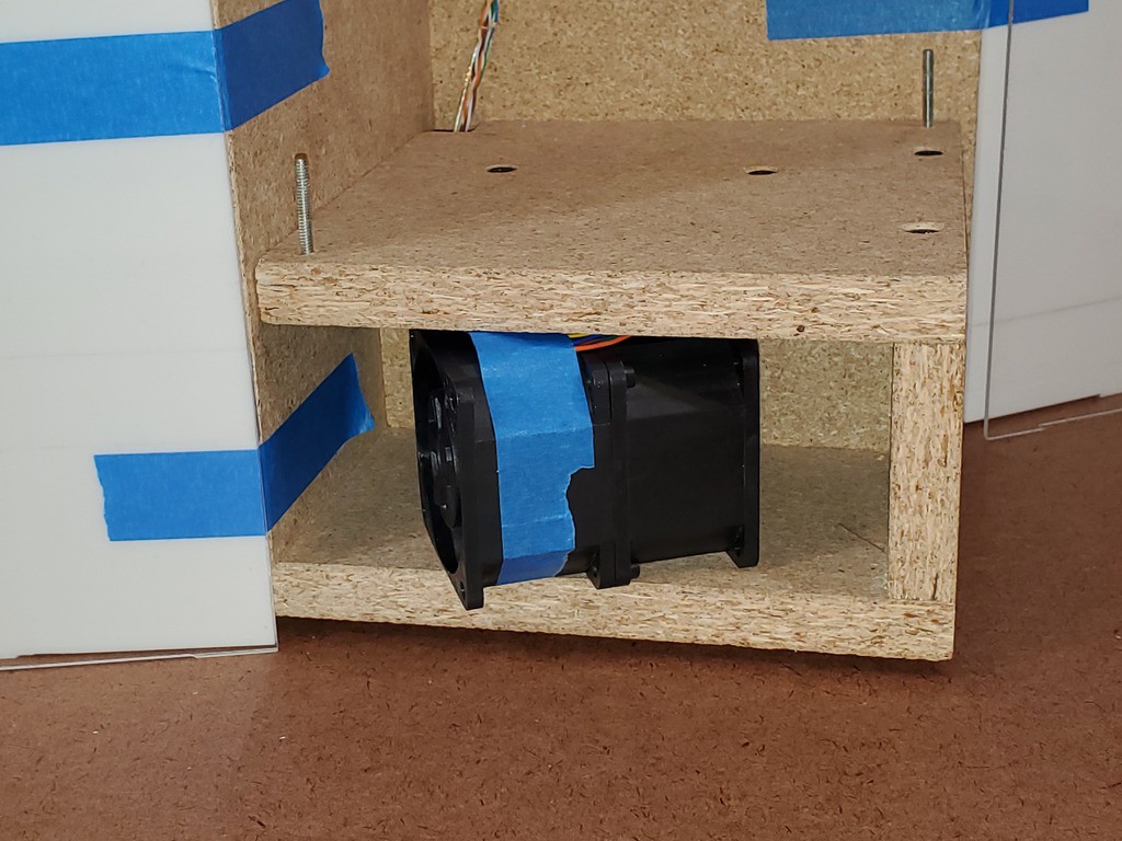
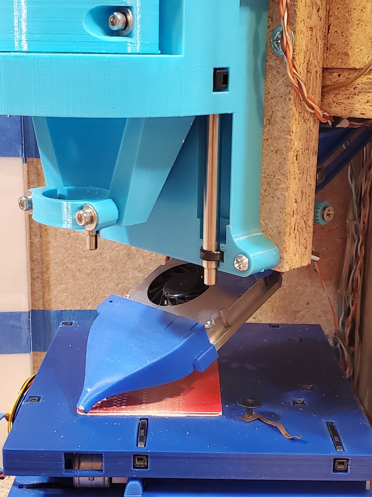
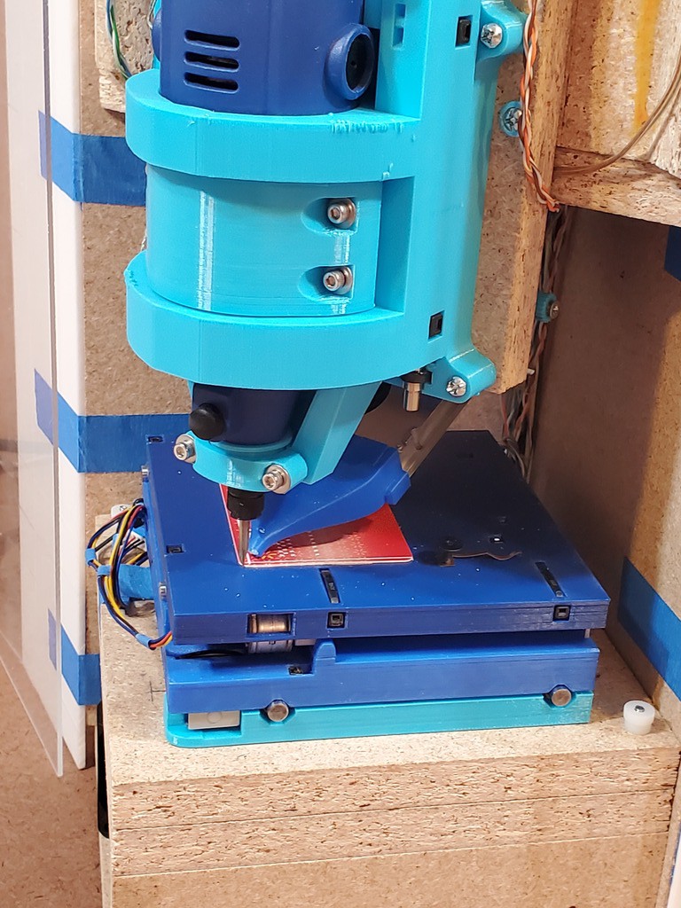
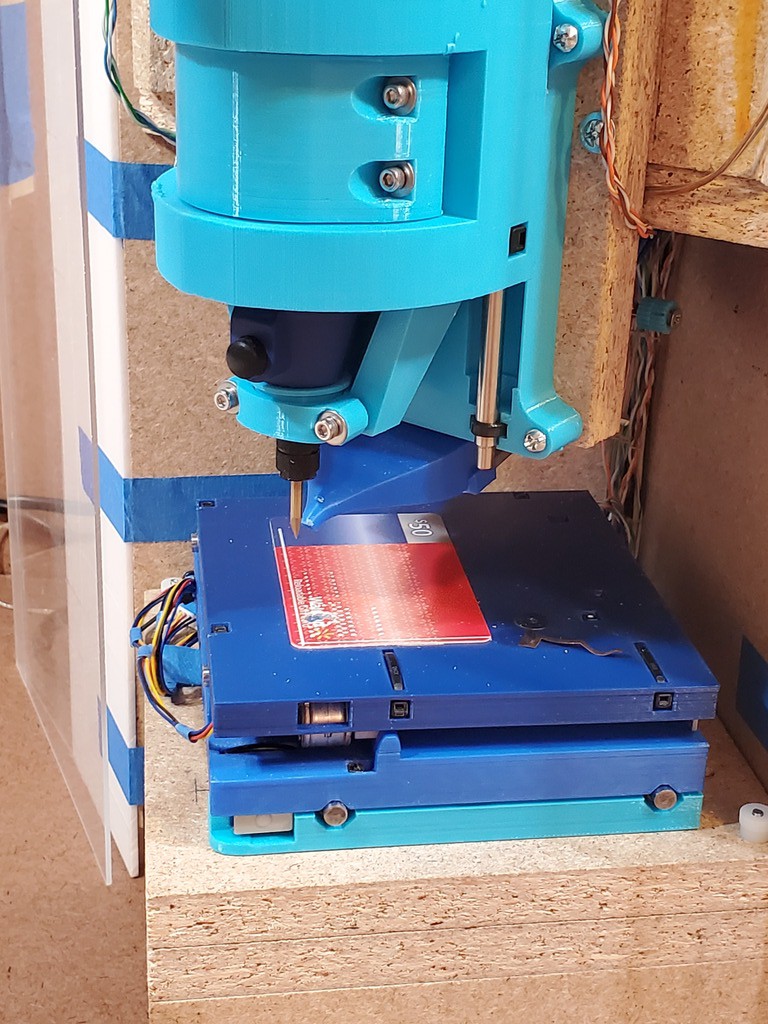
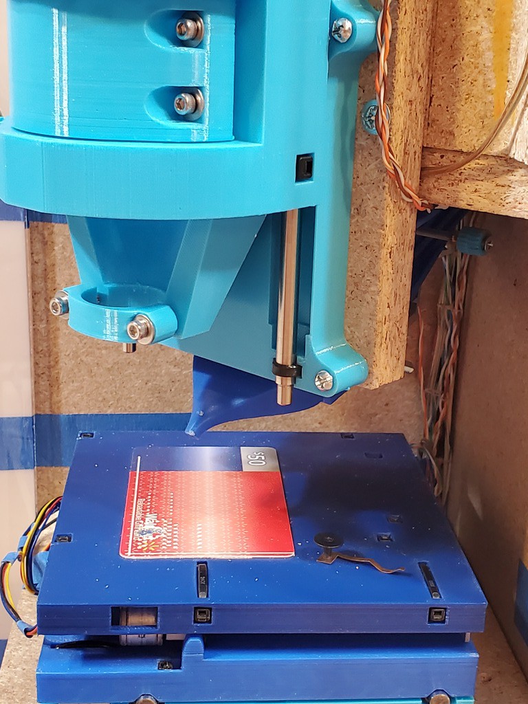
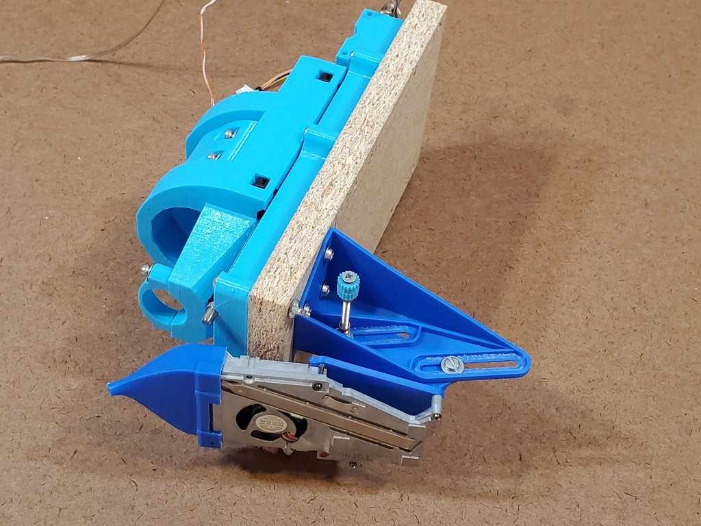
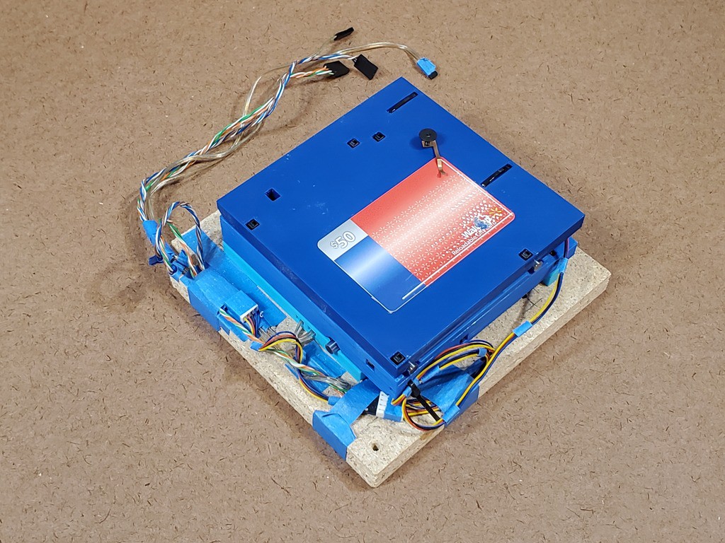 ...and which is stiff enough to pin down with two thumb nuts in the reachable pair of opposite corners.
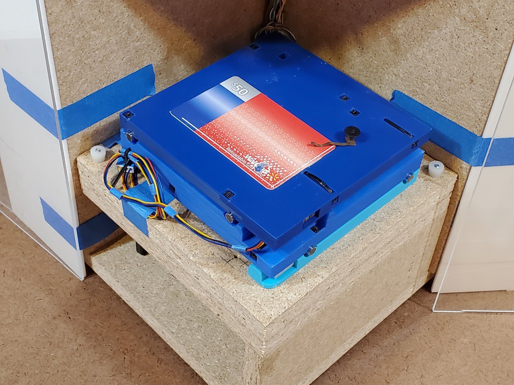 Actually this "first draft" started with wing nuts instead of thumb nuts. That worked. But they need a lot of room for the wings to swing. This version has the room but I was thinking of a frame shrink before MRRF. When I get to that, it will require something more compact. These thumb nuts are the current candidate for that.