 Xieshi Zhang
-
1Welcome to the assembly process!
This is going to be a long process.
![]()
Gather all the materials in the components section, including the custom PCB (see electronics assembly).
-
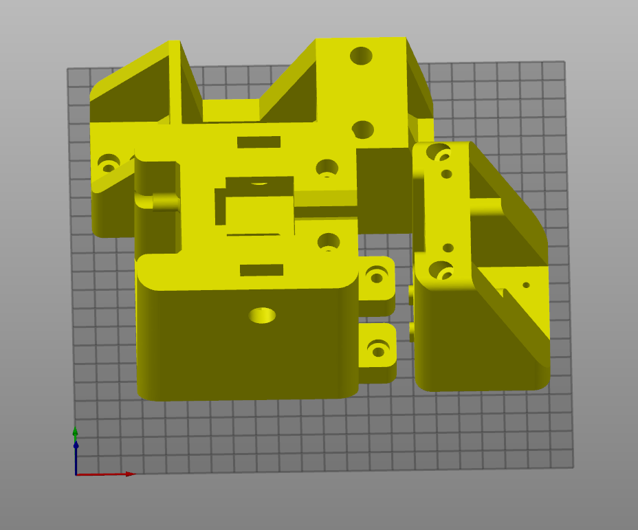
2Preparation of 3D Printed Parts
Let's begin with preparation:
Print the parts in the orientations shown in the picture.
![]()
![]()
The amount required are as follows:
- 1x Stationary Fixture
- 1x Moving Fixture
- 1x Moving Load Cell Mount
- 1x Stepper Motor Mount
- 2x Alignment Tool (Tool 1)
- 4x Grip Block
- 4x Grip Screw Head
It's recommended that the parts be printed with:
- Either 100% rectilinear or >30% gyroid infill.
- 6-8 perimeters/shells.
- A rigid material like PLA or materials of higher rigidity. DO NOT use (regular) PETG.
-
3Physical Assembly - Video
This is a video assembly animation. Detailed instructions will be below.
-
4Physical Assembly Stationary Fixture
- Place the 2060 aluminum extrusion on a flat surface.
- Get the stationary fixture and fit the 6001 bearing in the bearing holder. You may need to use a bit of force to get the bearing in, and you may sand the bearing holder to allow for a easier fit.
- On the back of the fixture, screw in the M5x90mm bolts directly into the plastic into the reinforcement screw holes. Doing so may require a bit of force, but with a proper Allen wrench, this should not be difficult.
- On the top of the fixture, there should be two nut insertion cutouts. Place M12 low profile nuts in those cutouts.
- On the top of the fixture, there should be two reinforcement mounting holes. These holes do not require the screw to thread in and should allow the bolts to directly slide in. Slide in the bolts all the way.
- Slide in M5x14mm bolts on all mounting holes of the stationary fixture.
- Fit M5 T nuts on all the bolts that were fitted, including the reinforcement mounting bolts. Do not screw the T nuts in all the way because they are meant to rotate and hold on to the aluminum extrusion.
This is a tutorial on how to use T nuts on aluminum extrusions.
![]()
-
5Physical Assembly - Linear Rail
This is the hardest part if you don't know much about linear guides (the fancier name for linear rail). Linear rails are precise components, so you want to work with them carefully.
- First, place the linear rail on the extrusion and align with the printed plastic tool and the cutout in the stationary fixture.
- If you received your linear rail and carriage block separately, very carefully align the plastic rail it came with to the metal rail. Make sure the carriage does not fall out of a rail (or otherwise you will lose the tiny bearings inside the carriage).
- Very carefully slide the carriage from the plastic rail on to the real rail, being gentle and correcting any misalignment on the way.
- Place M3x8 mounting bolts into the rails and use T nuts on the bottom to bolt the linear rail in place.
Linear rail manufacturers often recommend using a datum surface to help align the rail. In this case, precision is not required, and therefore plastic alignment jigs are sufficient.
![]()
-
6Physical Assembly - Stepper Motor & Mount
- Place the stepper motor mount on the other side of the extrusion.
- Insert the set of 7201 bearings. Ensure that the direction/setup is correct! Single row angular contact bearings are NOT symmetrical. You want the thicker outer rims to face each other.
- Mount the stepper motor. Use M3x8mm low profile bolts.
- Place M5x50mm bolts into the longer holes.
- Place M5x14mm bolts in the regular mounting holes and use the T nut technique to bolt the assembly down.
![]()
-
7Physical Assembly - Moving Load Cell Mount
- Place the moving load cell mount on the left linear carriage.
- Insert and screw in M3x8mm bolts so that the part can be fastened to the linear rail.
- Place a T12 flanged nut against the "wall" and align it with the mounting holes.
- Insert M3x22mm bolts and use M3 nyloc nuts to secure the T12 nut.
![]()
-
8Physical Assembly - Moving Fixture
- Place the moving fixture on the right linear carriage.
- Insert and screw in M3x8mm bolts so that the part can be fastened to the linear rail.
- On top of the moving fixture, there are two nut inserts. Insert M12 low profile nuts in those nut inserts.
- On the front of the part, there are two reinforcement screw holes. Thread in M5x90mm bolts in those screw holes.
![]()
-
9Physical Assembly - Load Cell
- Place the load cell in the appropriate position.
- Use M16x25mm hexagon bolts (or whichever one that fits your load cell) to mount the load cell. Finger tight is enough.
![]()
-
10Physical Assembly - Grip Assembly
- (not shown in animation) Apply 40 grit sandpaper or grip tape onto the grip blocks. Use super glue or strong epoxy to glue down the sandpaper.
- Slide in the grips one by one into their cutouts.
- Screw in the M12x50mm external hexagon bolts.
- Push the grip screw head onto the external hexagon bolts. It should have a tight fit if printed properly.
![]()
Low Cost Universal Tensile Testing Machine
An extremely low cost universal tensile testing machine made from 3D printed and commercial materials


Discussions
Become a Hackaday.io Member
Create an account to leave a comment. Already have an account? Log In.