Project contains lithium batteries - take care when working with them;
All dimensions are in milimeters;
Bolt dimensions specify metric size, bolt length specifies thread length (not total length); "Ф" is a diameter for whatever part it is specified; nut dimensions specify thickness alongside of thread size;
Every 3d object in this project and their dimensions are tuned to be correctly printed on my printer, and that is why you should be ready for cases when parts with tight dimensions (like attachment rails vs a handle attachment) are either too loose or too tight, and thus - STEP files provided for further ad hoc adjustments;
This guide does not include detailed steps for painting but may touch the subject a bit;
This guide may not include some late assembly stages that will be featured in project log, nor parts list will include parts that constitute those late stages (e.g. separate attachment assemblies - they will feature their own mini part list and build instructions in project log section), however i will try to keep files/archives up to date.
I will skip bootable image setup entirely - internet is full of stories like this, but i will mention that my build currently runs on Pop!_OS.
If it was not apparent already - brace yourself for the fact that English is not this hacker's native language;
So, are you ready? (Casio for scale)
2
Print parts
No step-by-step instructions here, follow your printing intuition/experience, but few tips would be:
I'd say print everything except small covers with 3-4 walls and 30-40% infill. Most parts do not require much printing support except maybe if you have trouble printing long bridges. Handle, skeleton hinge parts and ethernet carrier require support. Orientation wise - handles should be printed with their mounting points in same plane as primary case like so; zvychai_v4_skeleton_hinge_omega will require support in this orientation; ethernet switch carrier is best printed like this; zvychai_v4_handle_reinforcer_strapslot element will require support when printed flat on largest side;
There are parts that require large printing volume (zvychai_v4_primary_case is roughly 266x148x67mm) and are not pre-split for standard volumes (like my old e3). I've printed those via local printing services. However at some point i've cut the keyboard plate in half (zvychai_v4_bm43a_key_plate_left/right, but "whole" variant is also present) because local printing services can shove their per material gram rates up their hotend fan intake.
Parts that will be closest to heat sources (like zvychai_v4_primary_case) should be printed with something more heat resistant than PLA or you're gonna be upset with me. What i've found out lately is that Pi can get hot when CPU is loaded and especially when charger is connected (UPS HAT heats up the heatsink lmao) - a late discovered design flaw, but printing the case with PET(G)/Nylon (ABS for primary case will probably be out of the question) should get you going without fear of spontaneous deformation; batteries may heat up too when charging, but i've seen no screaming issues on that part atm.
If you plan on using stock skeleton hinge, you will need two of zvychai_v4_skeleton_hinge_omega and one of them should be mirrored.
Print zvychai_v4_paint_stencil_X only if you plan on painting the thing as they are here purely as stencils, not structural parts.
You will need 3x zvychai_v4_aux_cover to cover all aux connector holes.
If you have/plan to use strap, you're going to need 2x zvychai_v4_handle_reinforcer_strapslot and it should be printed with something that has higher tensile strength, or else you're in for a surprise impact test at some point. If you are not planning to use strap, zvychai_v4_handle_reinforcer should be printed instead - one per handle (photos depict only right handle in use that requires that reinforcer)
You will need 5x zvychai_v3_display_control_piston to reach display menu buttons. Feel free to print them horizontally to avoid heat creep on short travel distances.
Print zvychai_v4_attachment_ethernet_cover and zvychai_v4_attachment_ethernet_carrier if you plan on using ethernet switch with the board that i've linked inlist of parts. If not, you can leave left attachment slot empty or print another zvychai_v4_handle.
I will advise to print two zvychai_v4_handle - one will be carrying handle, second will be a sort of a stand - rather accidental design discovery that nonetheless works almost as intended.
Everything i've not mentioned before should be printed atleast once if you expect for your build to look close to pictures presented in the project gallery.
3
Printed parts preparation - painting, threaded inserts
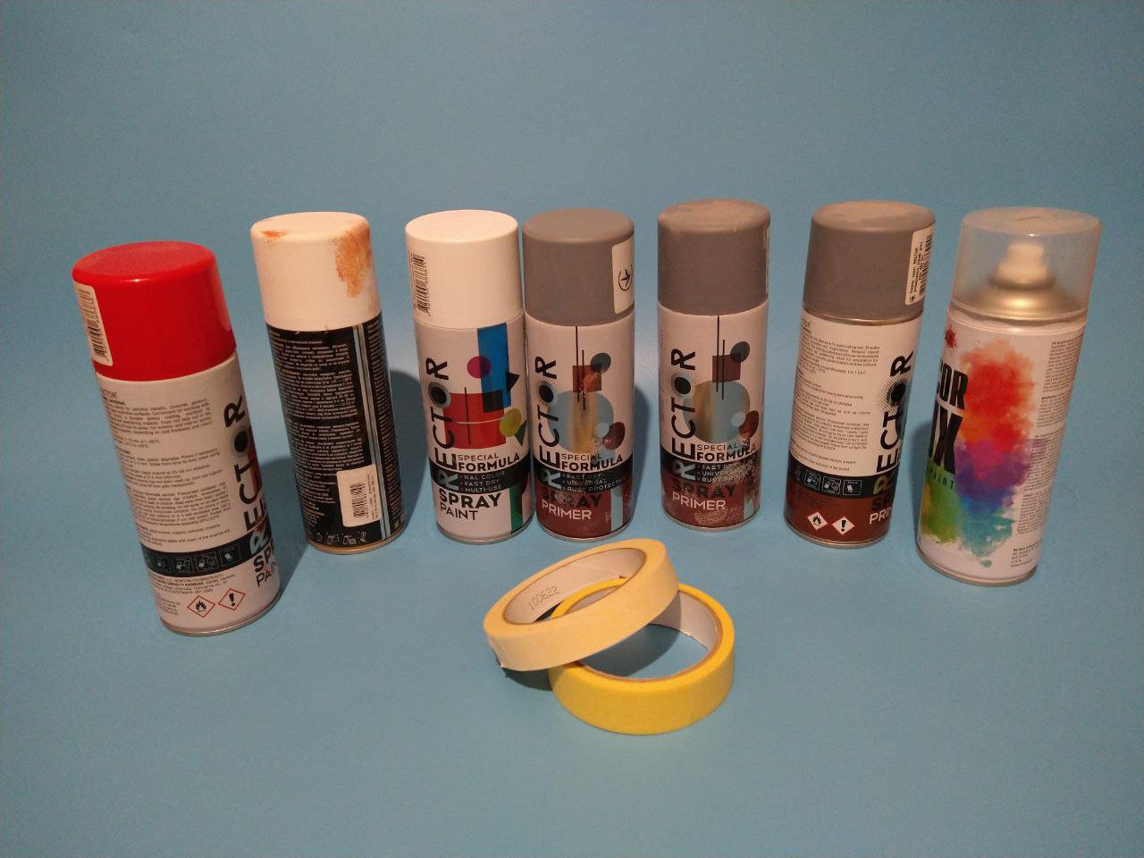
If you plan on painting parts, this is probably best time for it - before you thread in any wires, install any other parts and before you melt in heat insert nuts. Remember to sand surfaces, degrease them before priming and painting. I've used cheapest enamel primer i could find in my local all-in-one shop, then it was white and red enamel. Grab a painters tape to add patterns, follow 45 degree slopes and you too can get your unique blend of Dazzle camo and classic mecha vibe.
Or not, i'm a sign, not a cop. It's not pretty process, must i warn you:
But unlike painting, M3 heat set nuts (brass insert, threaded inserts etc.) are mandatory here.
Hope got yourself a kit of those. Grab a heat set nut inserting guide, practice on failed prints and get going.
You will need them in primary case, back cover, top right cover, top left cover and "spine" parts, in every Ф4.5mm hole that looks like a shallow "well" - that where they go. Most of them should be no longer than 5mm. Those wells that are on top covers can be shorter - 3-4mm long nuts should be ok.
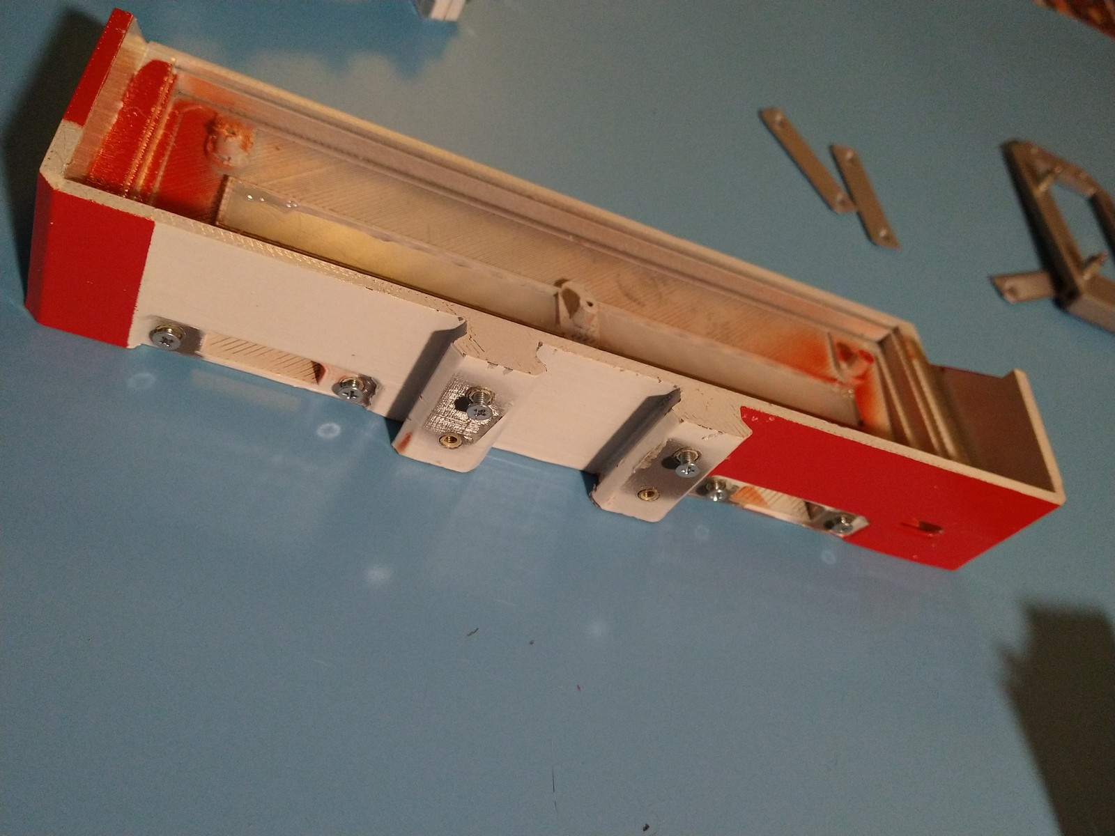
Basically, wherever you see a bolt sticking out on the following images, that where a thread insert is:
This part here is your bravery test - you need threaded inserts inside of the case for the battery caddy to be able to hold the Pi assembly tight. You will have to thread your soldering iron through the slot without melting it two times. SH72 with conical tip worked for me here.
4
So how do magnets work?
Clicky lid action is achieved by inserting 2x4 cylindrical neodymium magnets into special recesses on connector lids and back cover.
Just remember to put them inside with appropriate polarities before applying epoxy, or else you will get magic levitating lid box to entertain people with - but that does not come with connector dust protection functionality.
5
Raspberry sandwich with some spaghetti
There is no mention of acrylic insulator plate in part list simply because i've got mine from some other cooling system for the SBC and i have no idea where do you buy it separately. You can probably get away with printing your own - it should just cover whole board silhouette, but do not make it thicker than 3mm, or else it will not fit into primary case slot as an assembly mounting point. I've provided STL in files section for you to try - mounting point was modelled around that.
So, to put your raspberry sandwich together, grab your acrylic plate, 4x M2.5 4mm standoffs, 8x M2.5 5mm standoffs, 4x M2.5 nuts (picture there says M3 but it is actually M2.5), a copper heatsink and snap them between each other like so (remember to put some thermal grease/pads in appropriate places, you might have to wiggle things for them to be flush and snug after that):
You might have to file the heatsink for it to fit PoE header in it:
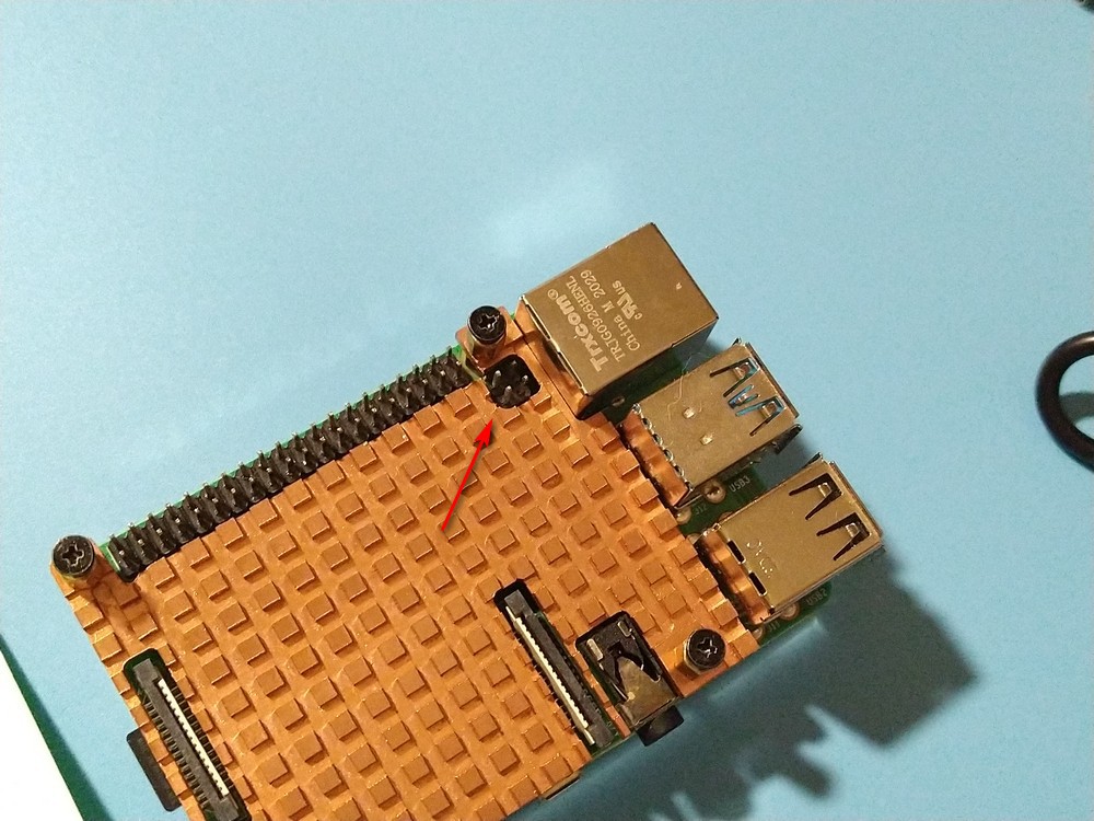
Now install your Geekworm X708 v2.0 UPS HAT. HAT kit will also provide some standoffs and bolts, so use those, they have nice flat pan head. Note the closest jumper to the fan, near the type-c connector - AON jumper should be open for the board to start only via switch press.
Now on to spaghetti and proscuitto. Grab your HDMI FFC parts and connect them together. For now forget about velcro - you will adjust FFC length later, but remember that they are fragile so bend really, really carefully.
Now for display power grab around 20cm of 22AWG wire, a XH2.54-2P connector (refer to X708 schematic on which exactly do you need) and micro USB male breakout. Check the polarity on the board connector and solder "+" to VBUS, "-" to GND, crimp other ends to the connector metal parts (look up how to crimp XH2.54 connectors, people been doing this even without tools, but you really dont want to solder to the UPS HAT, believe me). You should also thread wires through primary case because neither of the connectors will fit into wire slot on the back. In the end you will get something akin to this:
Double check your power polarity and it is a good opportunity to test if rails are routed where they should. I've used separate micro USB to power the display and HAT can start without batteries for now. Connect the power, press blue button on the HAT and if your Pi has bootable card, you should get something like this:
6
More spaghetti
Grab yourself another double 15cm 22AWG wire and crimp it with XH2.54-2P on each end. This will go between battery holder and UPS HAT. Double check polarity on the board and on the battery holder.
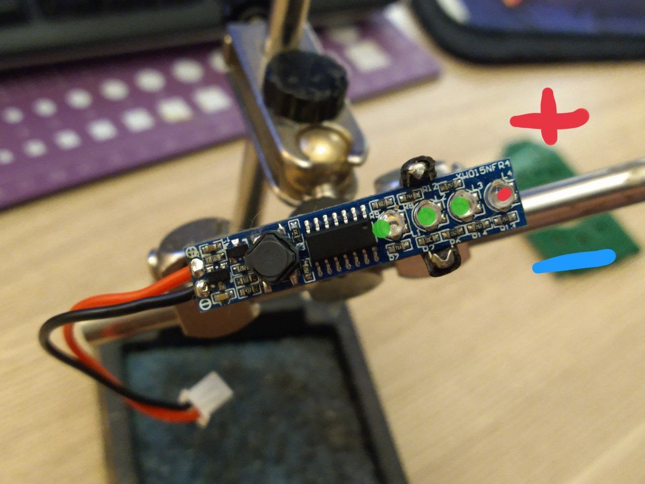
Now get thinner wire (switch kit connector wire is too short and you will need 3 more pieces of 6-10cm wire to extend it) and PH2.0-4P connector for power switch and LED. If you have ordered your power switch from Ali via link in component list, you will acquire a crimped connector alongside of the switch itself (otherwise you will need connector for the switch too). I would gladly direct you to a " How to connector external power switch " table on board description, but my board for some reason does not have "battery low LED" pin. So i've got my board external power switch routed like so (i've also added 200 Ohm resistor for LED because i don't know if power switch has resistor inside):
Crimp, solder, apply heat shrink tube if necessary and after all this you will have this set
It's also a good idea to double check all the polarities and connections and test if the board will be able to boot Pi from batteries.
7
Eye of Zvychai
Grab your 1S charging indicator and remove LEDs and the pushbutton. You're going to connect those square leds to the indicator board with short, thin wires. You should also solder voltage input to the indicator board (around 5-6cm) and crimp the wires on the other end to another XH2.54-2P connector - this can be connected to the battery holder. Use this as reference:
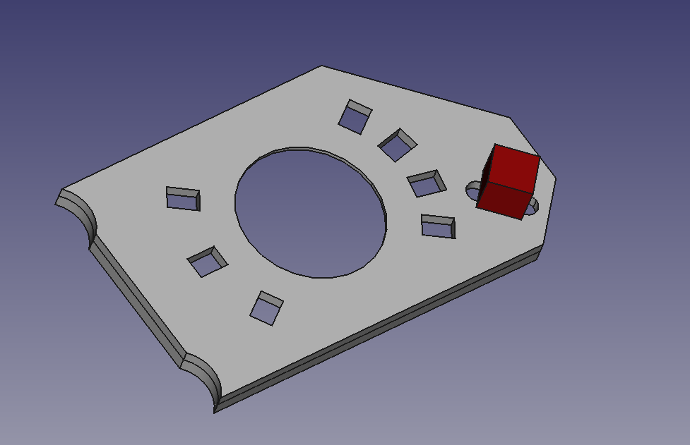
You will also connect button contacts via wires to that silent tactile button and glue this button on the back of the zvychai_v4_primary_right_cap_switch_led_riser part - between two holes that face diamond opening on the cap hull. Those two holes will be used for button wiring. Something like this (digital dramatization, button is red):
Now put riser panel against the inner part of the cap. If it for some reason does not fit, you can use XActo knife or similar to hack away plastic on the back of the primary cap to accomodate for switch pins. In the end, it should protrude like this
By the way, 4 charge level indicator LEDs go to the right. After you have soldered in the button, you can glue riser panel to the cap, but remember to align LED holes. After riser panel is installed, you can put LEDs in corresponding holes and hotglue the charge level indicator board and screw in the power switch. In the end, the innards of the indicator panel should look like this:
Note that LEDs to the right are not connected - in my build they will be routed to Pi GPIO for notifications and whatnot, but you can route them anywhere you like, this is part of the "it tries hard to be extendable platform" attitude.
If you have connected everything right, this should be the result:
And when you connect power switch header to the board and the board is powered, you may be greeted by this:
8
Bolt on the spine, put the heart in
Prepare to install the screen and to bolt the "spine" to it. Display button pistons should also be ready for this phase.
You can temporarily affix the display with 1/4 tripod bolt so it won't fall off in further steps. Just don't bolt it in too tightly, leave a wiggle room.
Put the button pistons in the spine armature, aligning the slopes:
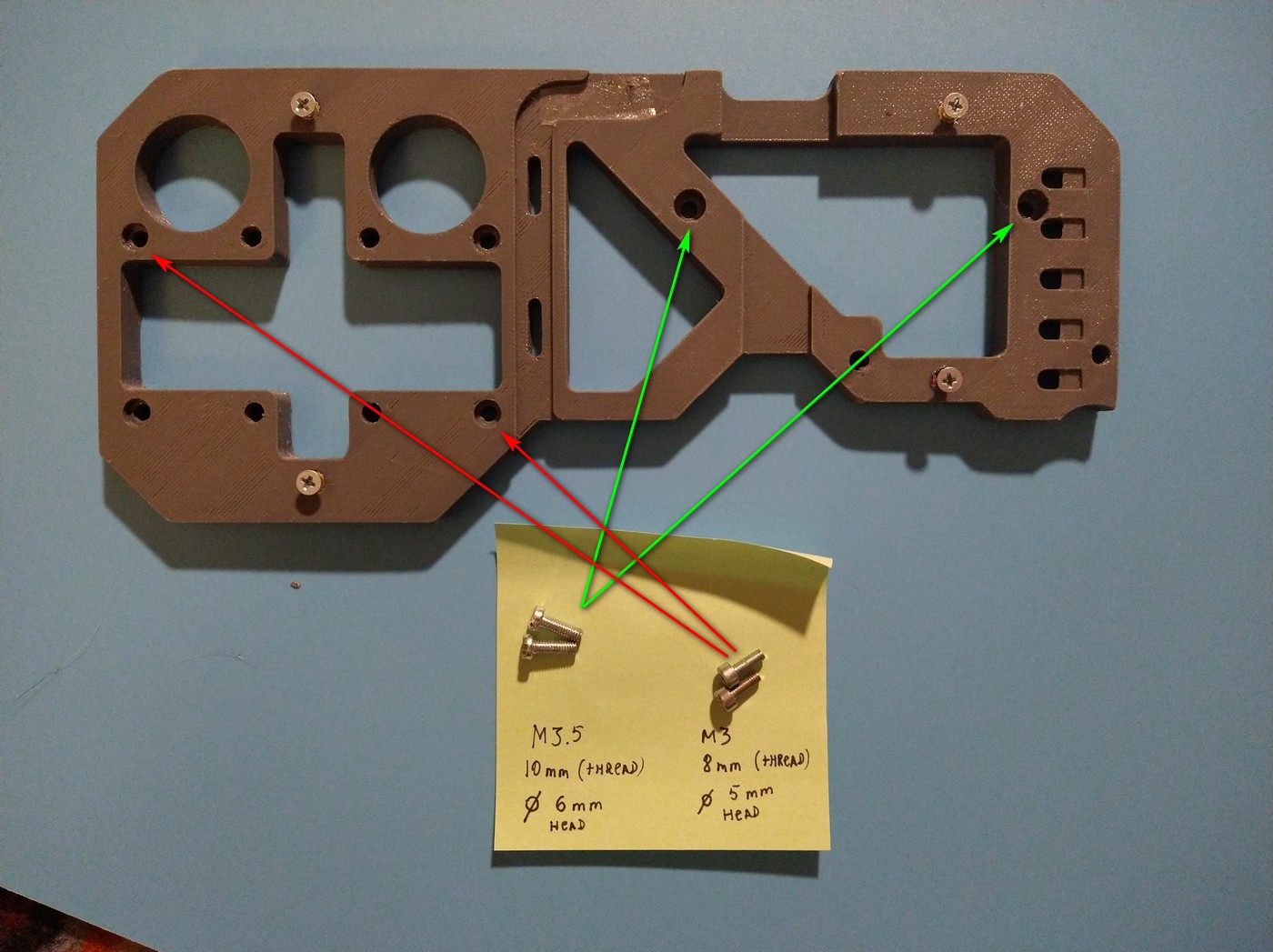
Remember those weird M3.5 bolts? You use those to put together the display, the primary case and the spine together. It's like a sauce. M3.5 go to the right, and M3x8 go to the left:
I assume you have connectors in the HAT like so (fat red-black to the battery, yellow-green to auxiliary power output - to the display, 4 pin to the switch, AON is open)
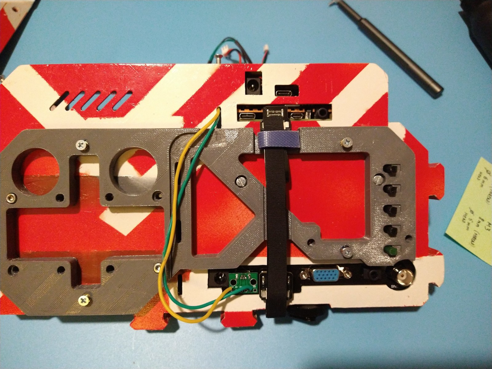
Now cable-manage the devil out of it, because if any of those wires cover the fan - boom you will have none of that silent cooling it provides. And watch for the blue button. Mine is routed like so:
Now comes the fun part. Put the assembly inside, so that connectors face their openings to the left. Carefully align bottom nuts and the insulator plate so that nuts go into eliptical recesses and insulator is caught in the plate holder bracket. After that, push the whole assembly down to insert nuts into the recesses and slide the assembly to the left.
It's ok to try it a few times. Remember that no wires should be caught up in the cooling fan and power switch and battery wires should go to the right. Display wiring should be stretched to the back as far as possible so none of it's free length is inside - this is important for later.
Now turn it around again - install the HDMI FFC and connect the display power. There is a duct in the spine that you can lay wiring into. This is where you also adjust the FFC length, use some tape or velcro to fix the bend, but do not bend it too hard or it will snap and no cyberpunk imagery for you.
Can i stress enough that you should test everything after assembly? No, i cannot.
Now put the back panel and lids on
9
Battery caddy assembly
It's not mandatory to put it together like i do here - you can omit the standoffs and just use 4x M2.5 bolts and 4x M2.5 nuts and call it a day.
However those standoffs are here for the purpose of rising the battery holder over the caddy (washers are for shimming there) just enough to allow you to install a micro SD card extender, connect it to the Pi and route the extender somewhere on the external attachment - so you can swap boot images without undoing the cap and removing the caddy for SD card access (haven't tested the perfomance impact this trick applies on the build). But this hack is not used in the build currently and is for a brighter time.
Now install battery holder on the caddy (it's a good idea to remove batteries first because that M2.5 bolt combined with XH2.54 connector pins will definitely be enough to either blow the holder fuse, or to turn the thing into a portable hand warmer):
Put the caddy in the primary case and bolt it in with 2x M3x6 bolts using long screwdriver via opening in the top part
If your printing is good enough - Pi should be pressed down with caddy pushing on the insulator plate, which is basically all this internal mounting construct was about - two boards, one mounting point.
10
Put primary together
Pretty self-explanatory. Connect the connectors, cap on the caps, stuff like that. It is important to note that right cap front bolt (near the charge indicator button) is M3 x 10mm bolt. I have not tried 12mm but if right cap underside "finning" is able to sink completely into primary case, 10mm bolt should be enough to reach threaded insert on the other side. If there is space between front of the cap and primary case - chances are your printer flow calibration is a bit wonky and you got a corner that does not allow to pass the finning inside - some cutting must be applied.
 mkdxdx


 Now put riser panel against the inner part of the cap. If it for some reason does not fit, you can use XActo knife or similar to hack away plastic on the back of the primary cap to accomodate for switch pins. In the end, it should protrude like this


Discussions
Become a Hackaday.io Member
Create an account to leave a comment. Already have an account? Log In.