 mkdxdx
-
11Strapping up
You could say installing a strap holder is optional, but it shows how to bolt it to a handle, and i think handle is too nice to be skipped. But there won't be many details because it is somewhat straightforward.
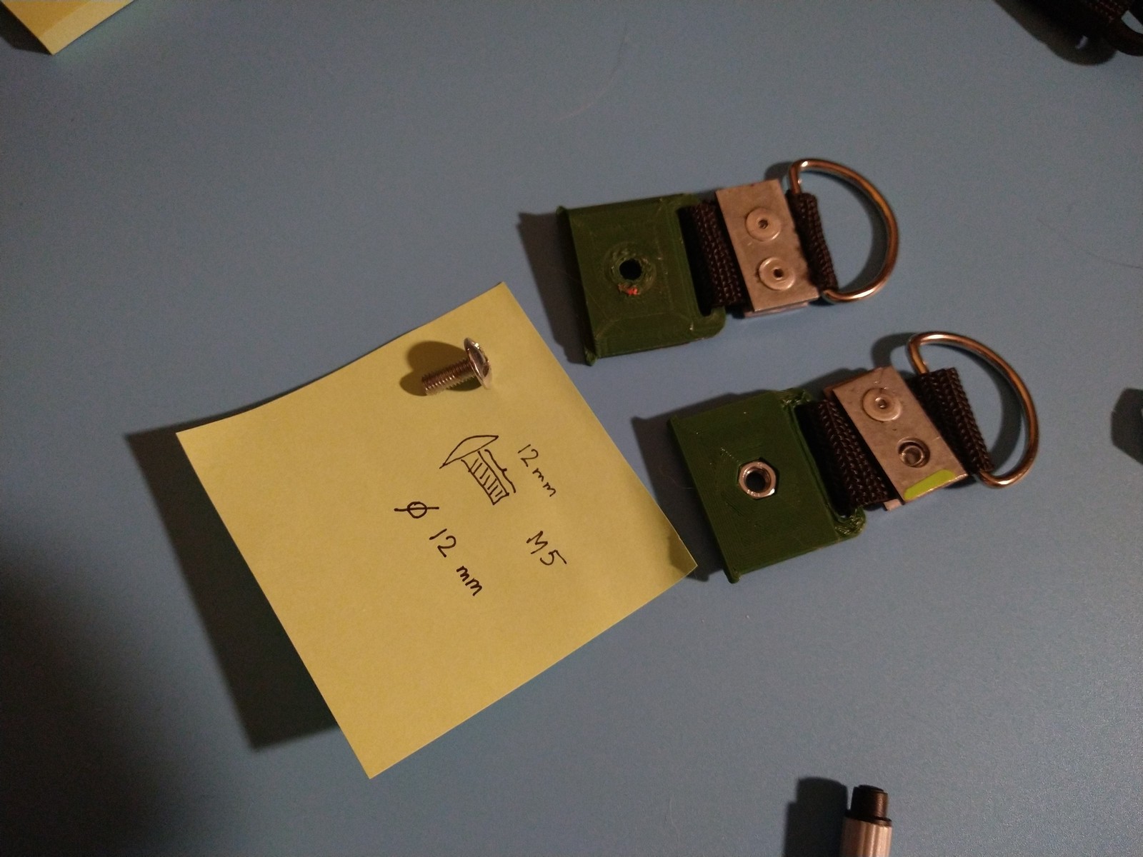
You basically print strap holders, pass a 25mm nylon strap through them and through a half-ring, rivet them together and call it a day.
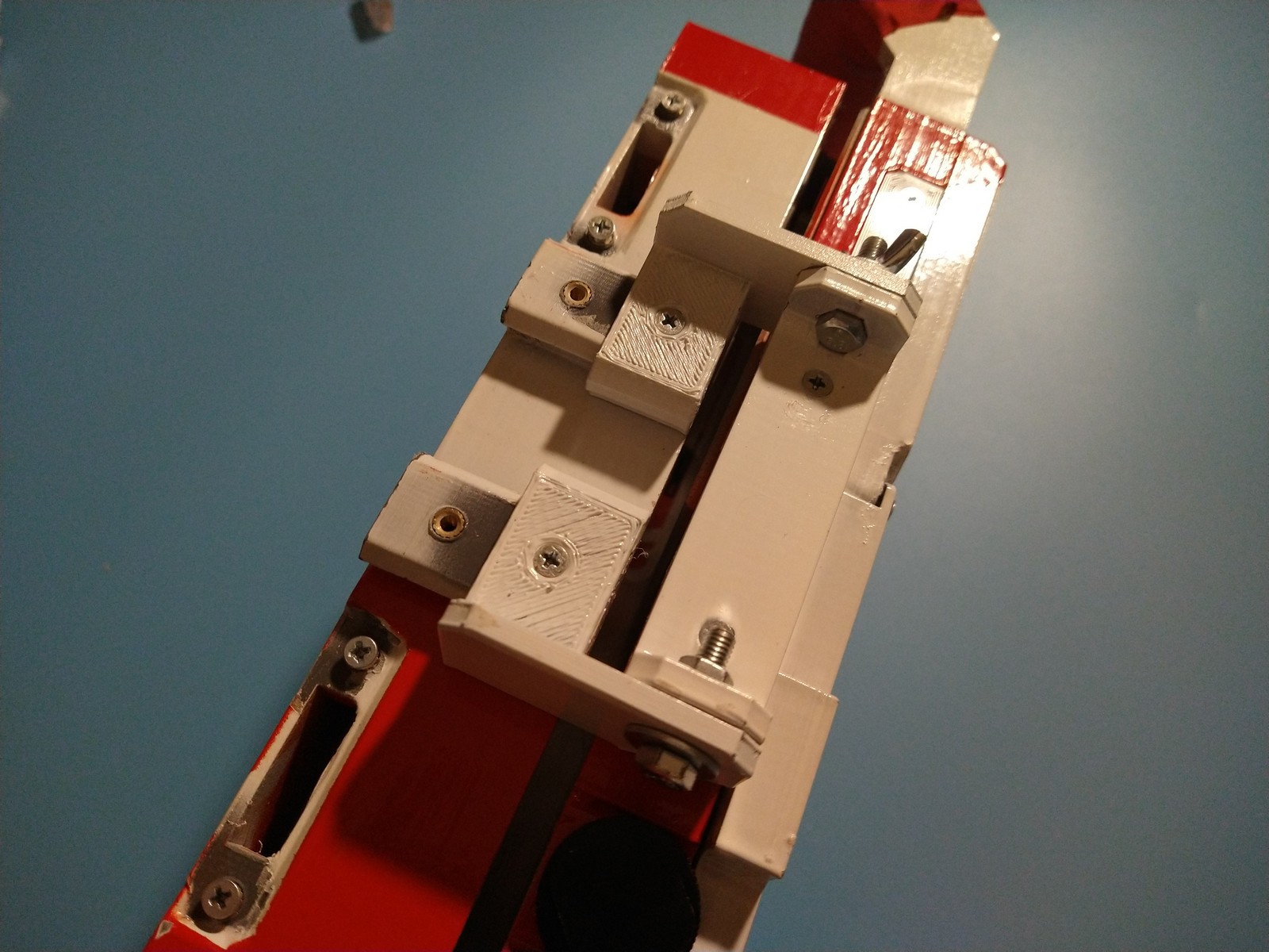
Then insert M5 nut into one of the strap holders (the one that will have handle over it), and slide strap holders under the mounting rails to either sides of the primary case.
![]()
![]()
Assuming you have printed the handle, get 2x M3x6 bolts and truss head M5 bolt and then it's assembly to a strap holder will look like this:
![]()
![]()
If you have carabiner strap available, you already can attach it and hang the thing someplace.
Oh and, red hockey tape for that handle:
![]()
-
12Keyboard assembly
I should have put a warning somewhere for you not to rush to soldering key switches to the keyboard PCB, because this is where it should start. You could solder LEDs tho.
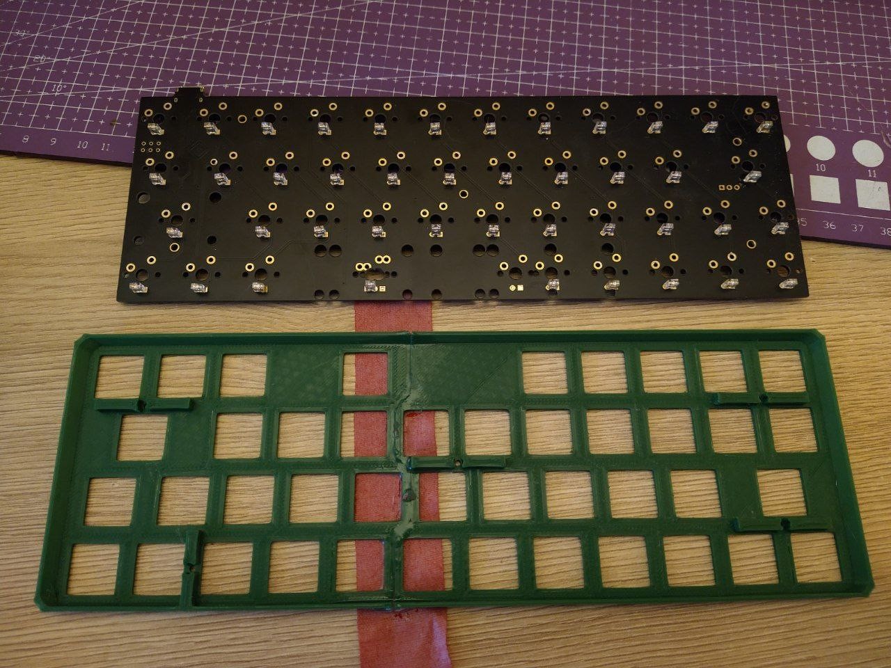
After you have printed the key plate (if you printed the partially cut version, you will have to epoxy them together now), the process is somewhat straightforward:
![]()
![]()
![]()
Make sure bolt holes and key holes align, or you, i must stress it, will be upset with me. After that you can install key switches and try to insert the assembly into the PCB for further soldering. It is also good idea to test the board without panel and all that jazz before final steps - unsoldering everything is not fun.
![]()
Before you install PCB with keys and key panel inside keyboard carrier, you probably should flash the appropriate firmware. In the files section there is a zip with QMK configuration that you should put into your QMK repo/installation repository (i'm talking about QMK "sdk" or buildable sources, not the QMK configurator). Latest QMK repo version provides base configurations for KPRepublic BM43A and you can just extract provided QMK config archive into BM43A folder inside the repo:
./keyboards/kprepublic/bm43a/keymaps
What you then should do is open config.h in bm43a directory and change define RGBLED_NUM to 6 and also add to the end of the file the following lines:
#define RGBLIGHT_EFFECT_ALTERNATING
#define RGBLIGHT_EFFECT_BREATHING
#define RGBLIGHT_EFFECT_KNIGHT
#define RGBLIGHT_EFFECT_RAINBOW_MOOD
#define RGBLIGHT_EFFECT_SNAKE
#define RGBLIGHT_EFFECT_STATIC_GRADIENT
#define RGBLIGHT_EFFECT_TWINKLE
This should enable all the rizz for that RGB aperture to shine. Now build the firmware (i do hope i don't need to guide you through installing the QMK because of how much pain it was for me) and specify "zvychai" board to apply keymap, get the the hex file out, connect the keeb with QMK Configurator running and flash it. Or look up how to flash the QMK firmware.
So now, when you hopefully won't be needing easy access to ISP header on the board, you can focus on the keyboard carrier.
Cut acrylic diffuser to the size of the aperture and put it inside. Hot glue fixation is totally acceptable, trustmeimanengineer:
![]()
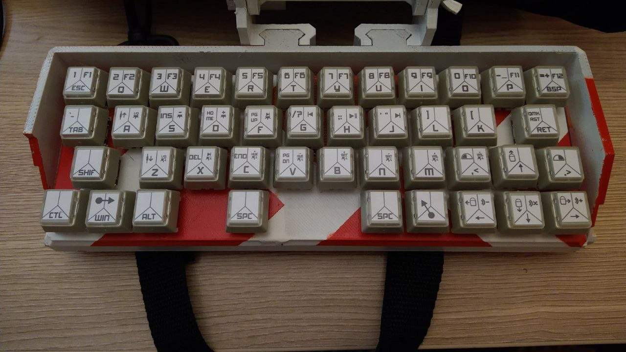
You surely can prepare keycaps also. I have not specified them in the component list, but if you are in a possesion of Cash desk/POS terminal keycaps, legend of which can be swapped, you can print provided SVG and after a bit of cutting action, you get these:
![]()
You know what to do. Then grab them smol 5x M2 fellas
![]()
Put the board inside the carrier, aligning the USB connector and start bolting it on. Boom, breathtaking:
It's also a good idea to test the keeb at some point. -
13Hinge assembly
Grab both M5 x 20 bolts, align alpha/omega hinge parts together, apply washers to the external side and put on the wing nut:
![]()
You can do this also with the hinge already installed on both keyboard carrier and primary case, but if you did not - do it now. You also should now install M3 x 6 for additional fixation.
![]()
![]()
![]()
As a side note - it's probably going to be easier to cover all the auxiliaries (those ugly openings with bolts to the sides) before you install the hinge, using 6x M3x4. There won't be a separate step for that.
-
14Ethernet attachment
You're still here? Ok.
Grab 2x M2.5x5 and bolt the ethernet switch board onto the switch carrier. This where you also add 5V power to the switch board - i do not think these boards come with XH2.54 headers installed, but if they dont - you need a pair of those. Or just, you know, solder wiring directly and call it a day.
![]()
Grab 4x M3x6 and assemble it's cover.
Then install it onto the left mounting rails. Thread in a little velcro strip to the back slot - this is a cable management feature.![]()
![]()
-
15Strike a pose
That should be it. Tighten the hinge bolt (the one without wing nut) and adjust the tension with wing nut only.
Install the second handle to the back of the keyboard as a stand.
Unfold the machine and behold.
![]()


 What you then should do is open config.h in bm43a directory and change define RGBLED_NUM to 6 and also add to the end of the file the following lines:
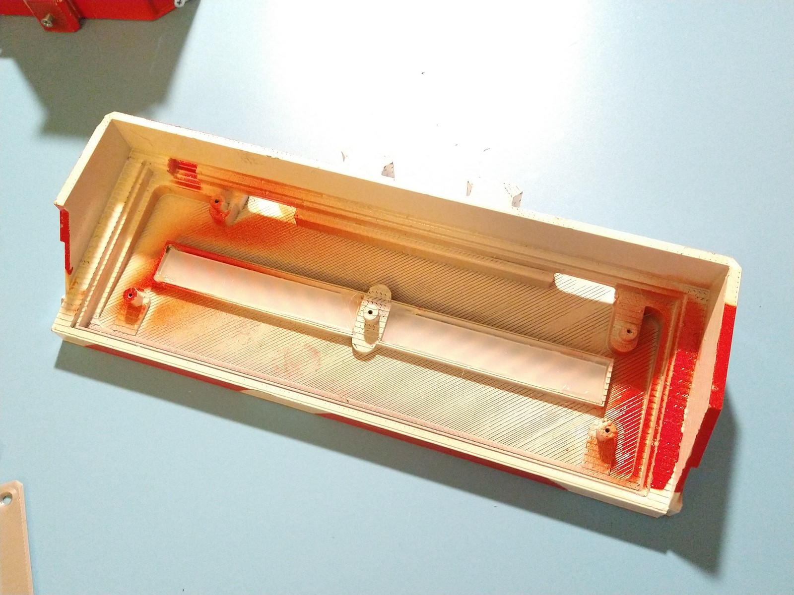


Discussions
Become a Hackaday.io Member
Create an account to leave a comment. Already have an account? Log In.