-
1Get a case
Ultimately your case is going to be one of the biggest constraints. If you don't already have one, figure out which one you are going to use then get the specs or buy it and measure it in person Once you know the size constraints of your case, you can figure out how much you can stuff in it.
Once I had my case, I verified the factory dimensions with my own measurements (always double check) to determine the interior dimensions of the case. Because I already had some parts and cables, I was able to dry fit in some of the components to begin to visualize how'd they stack and where cable routing and access points might go so I can be aware of any space constraints. I didn't yet have all of the parts so at this stage so I took a step back and began to model the interior frame and front panel design in Fusion 360 by roughing in the parts I had at that point and then creating placeholder objects if I could find the dimensions online. This allows me to make some progress on two fronts while I collect all the gear; 1) it helps me virtually organize the interior components and front panel and 2) later in the process I can take the CAD files and use them for CAM like to 3D print, laser cut or CNC elements of the deck.
-
2Shield the case
Having the case before I have all of the other parts allows me to begin work on shielding my deck. I am currently planning how to implement this shielding. I have a background in electronics so I am not completely clueless and I have some ideas but I am going to do some research on shielding and faraday cages before I jump in.
Currently I am thinking of 2 layers each layer alternating a layer of foil tape and a layer of kapton tape for each the case and the case lid. The lid and case would be electrically bonded at the base layer by way of a exposed copper braid or other connection between the two. I need to read up a little bit to validate my thoughts but if there are 2 layers of foil and the layers are not bonded to each other, there should be a small amount of capacitance created between the layers that could also dissipate any differential charge and further protect the interior. That's just me spitballing though, I'm not sure...it's just a thought.
I was also thinking of layering in some kind of mesh material akin to chicken wire (but finer) in between the layers but I still need to do more research.
Another random Idea I had was to do a cross pattern of narrow copper foil tape as a layer on top of the foil tape but I need to so more research.
I am thinking of ways to ensure the foil tape is electrically connected with the adjacent pieces of tape, on it's layer I think it matters but not sure...
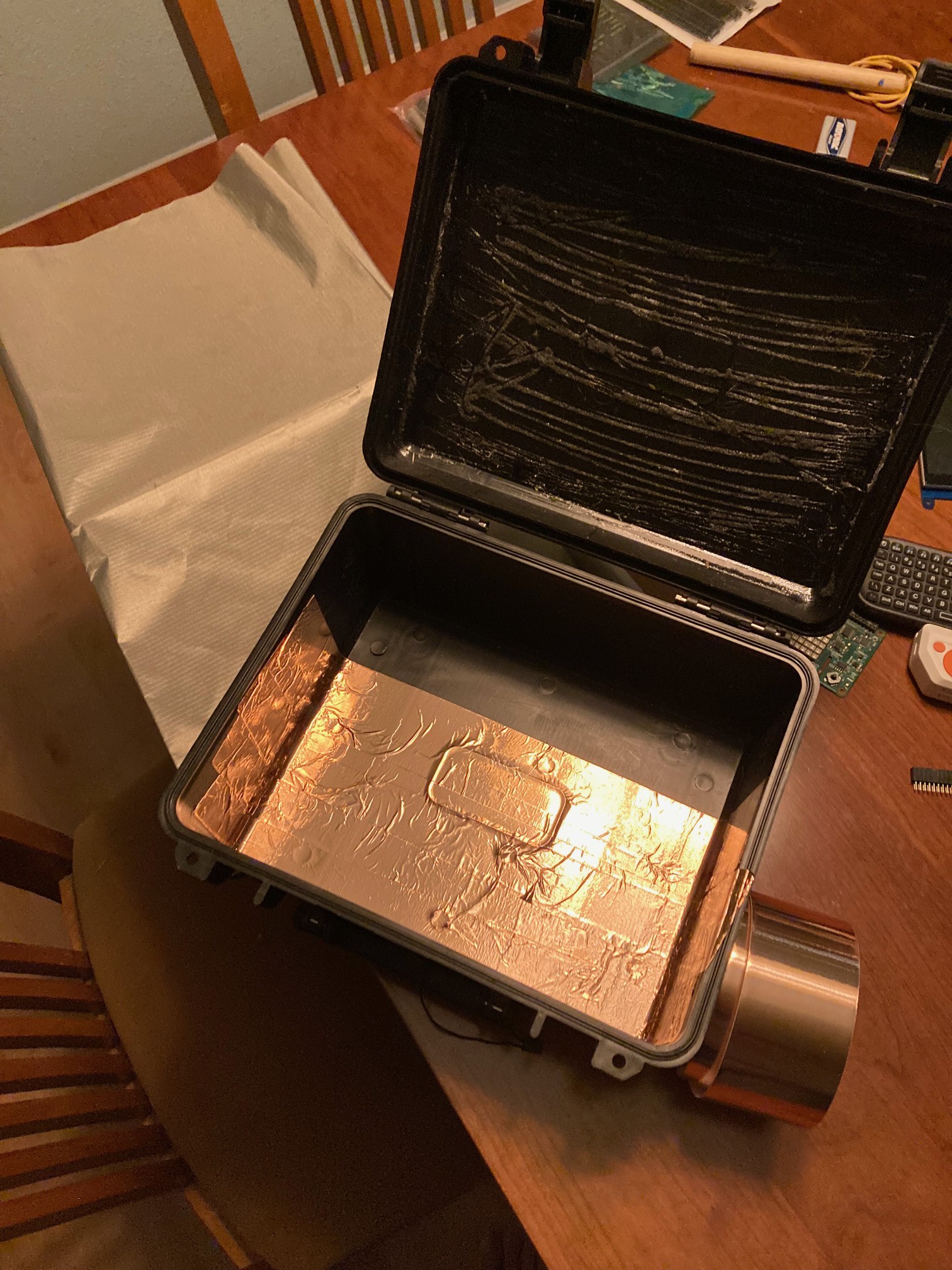
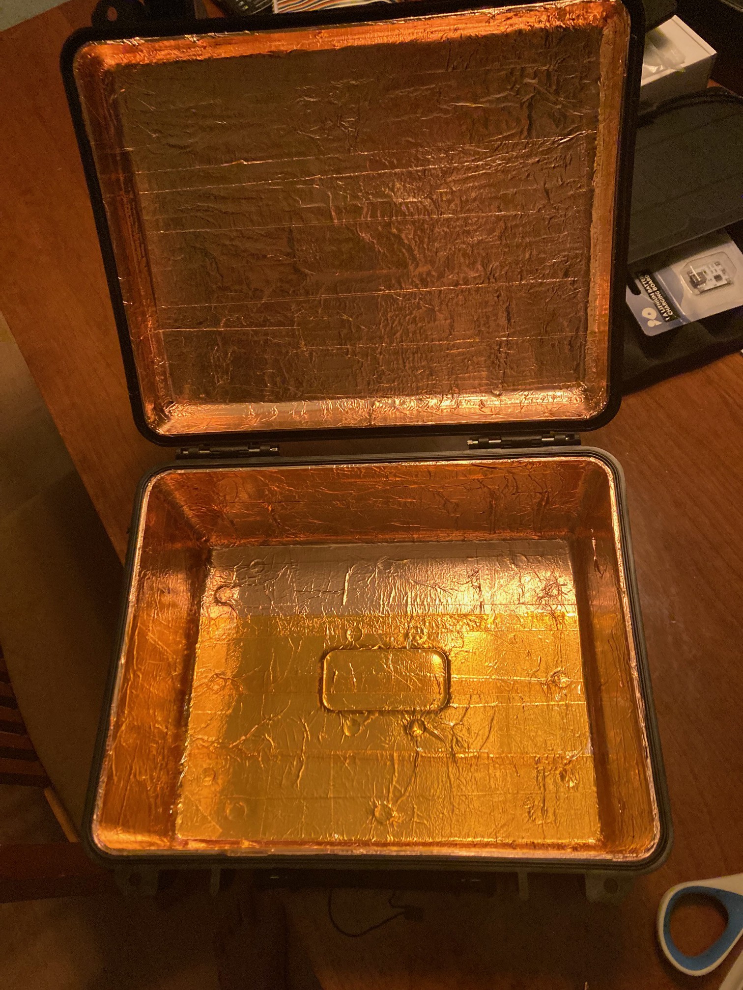
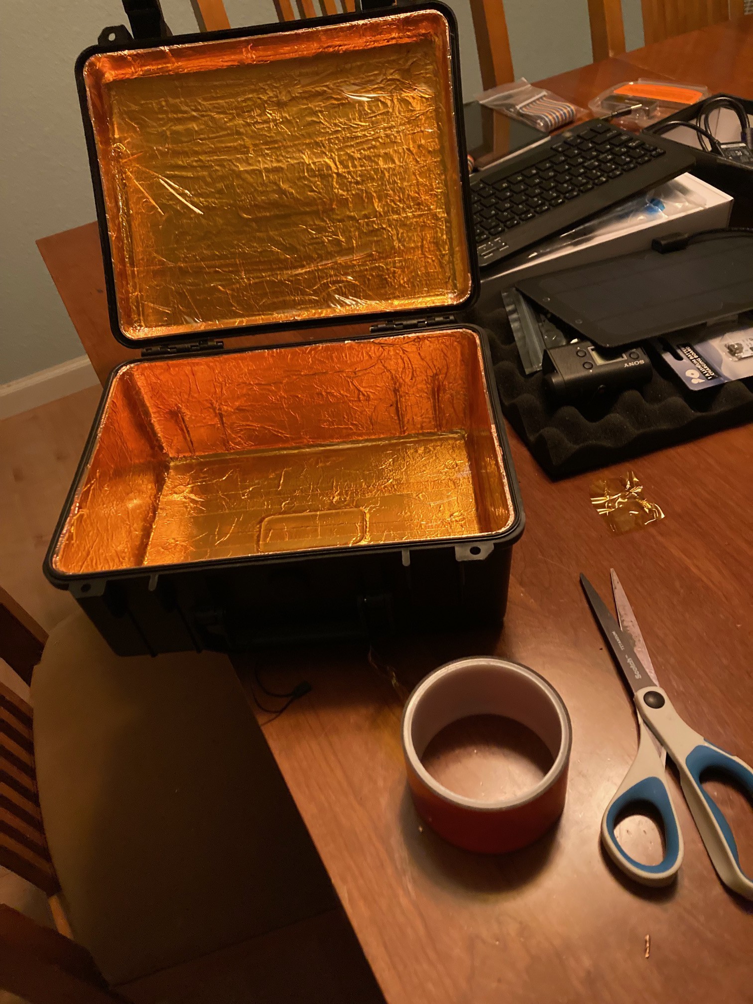
UPDATE: Started and finished the copper foil tape and Kapton insulating tape application. Now working on the shield cloth layer. I am expecting a low VOC adhesive spray to be delivered in a few days which I'll use to bond the fabric to the kapton layer...stay tuned
partially covered case
![]()
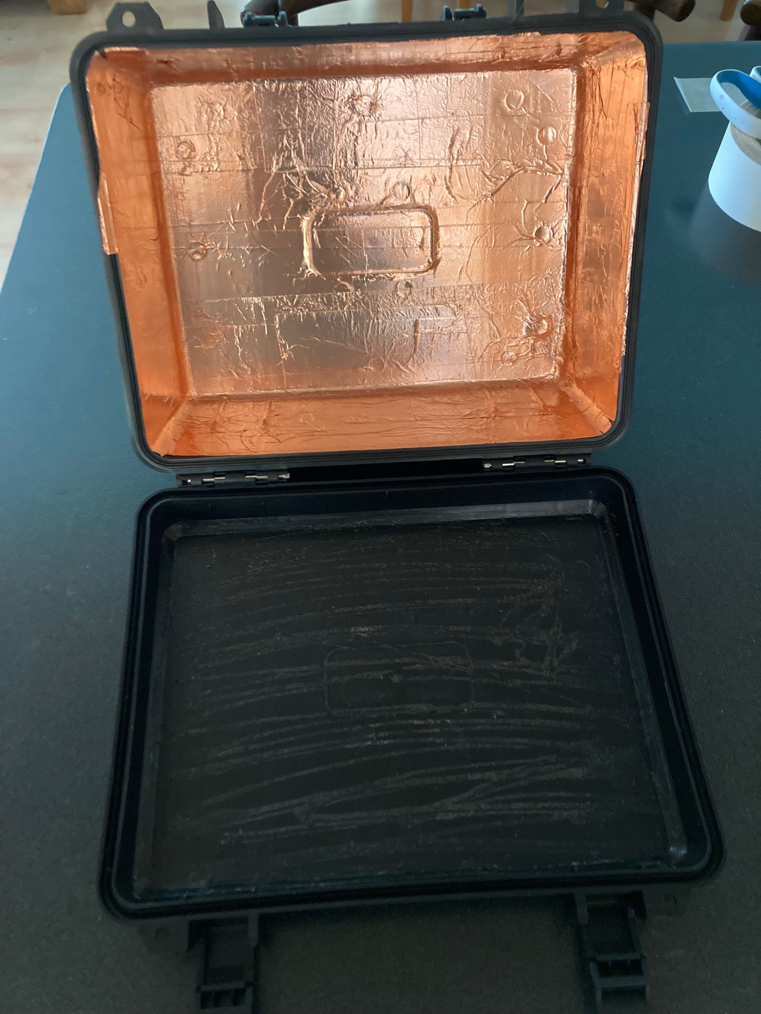
And a mostly complete layer, I have some touch ups around the edge.
![]()
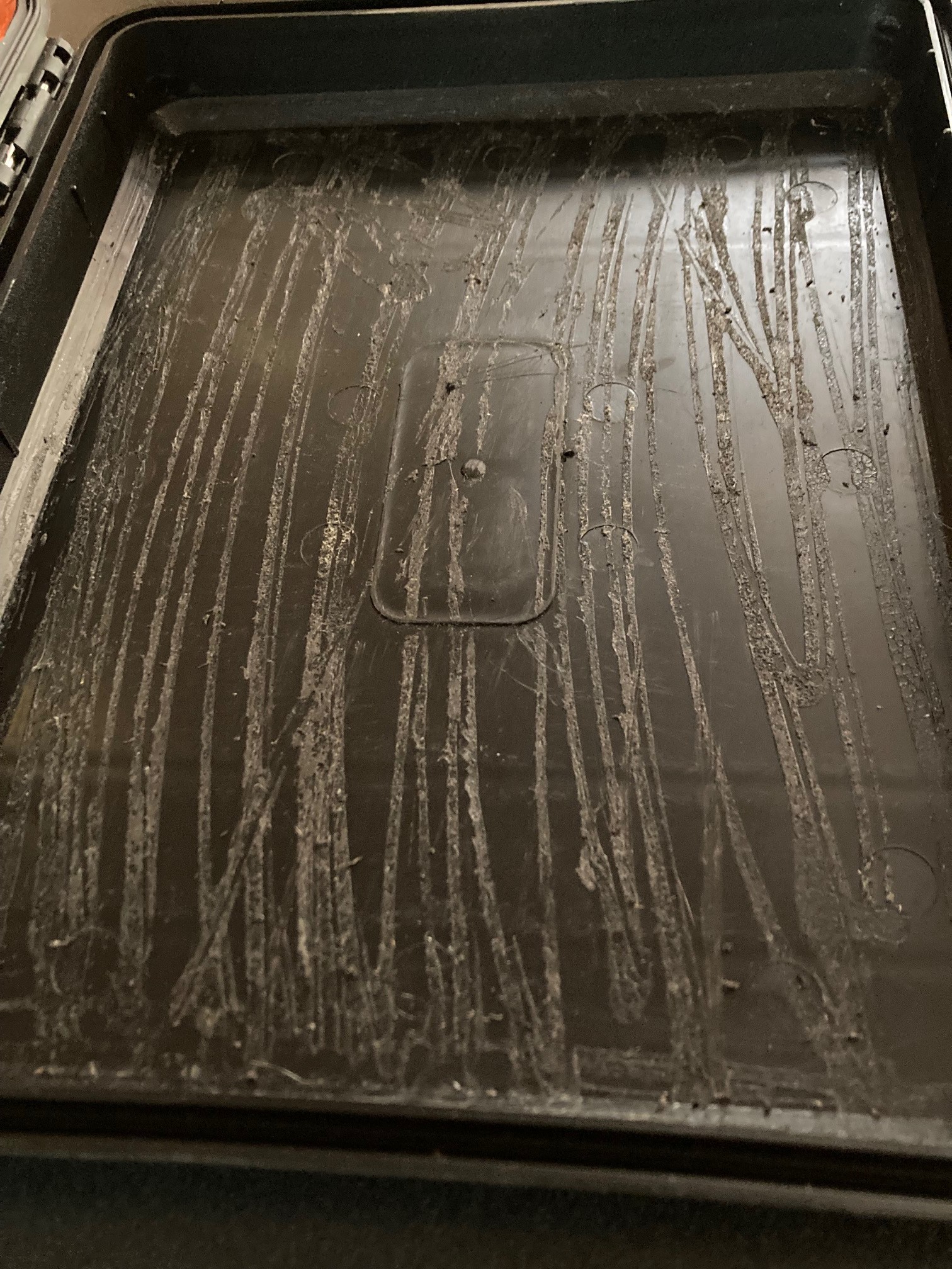
You can see that after I pulled the foam off of the lid, there is an excessive amount of residual adhesive. I 've been attempting to scrape this away before applying the shielding to the lid. Although this is much improved, I am going to try a couple of other methods before moving forward.
![]()
So I got the lid to an acceptable prepped state then proceeded to complete the copper foil layering. The pic below shows the nearly finished first copper layer.
![]()
My attempts to solder directly on the silver infused fabric have been unsuccessful. My new plan is to sew braided copper between the lid and case directly onto the shielded fabric pieces as an electrical bond. For cost and simplicity I am going to use basic solder wick as this cabling. It's flexible, low profile and I think will work well for this purpose. I have some conductive thread I'll use to sew the solder wick to the silver fabric.
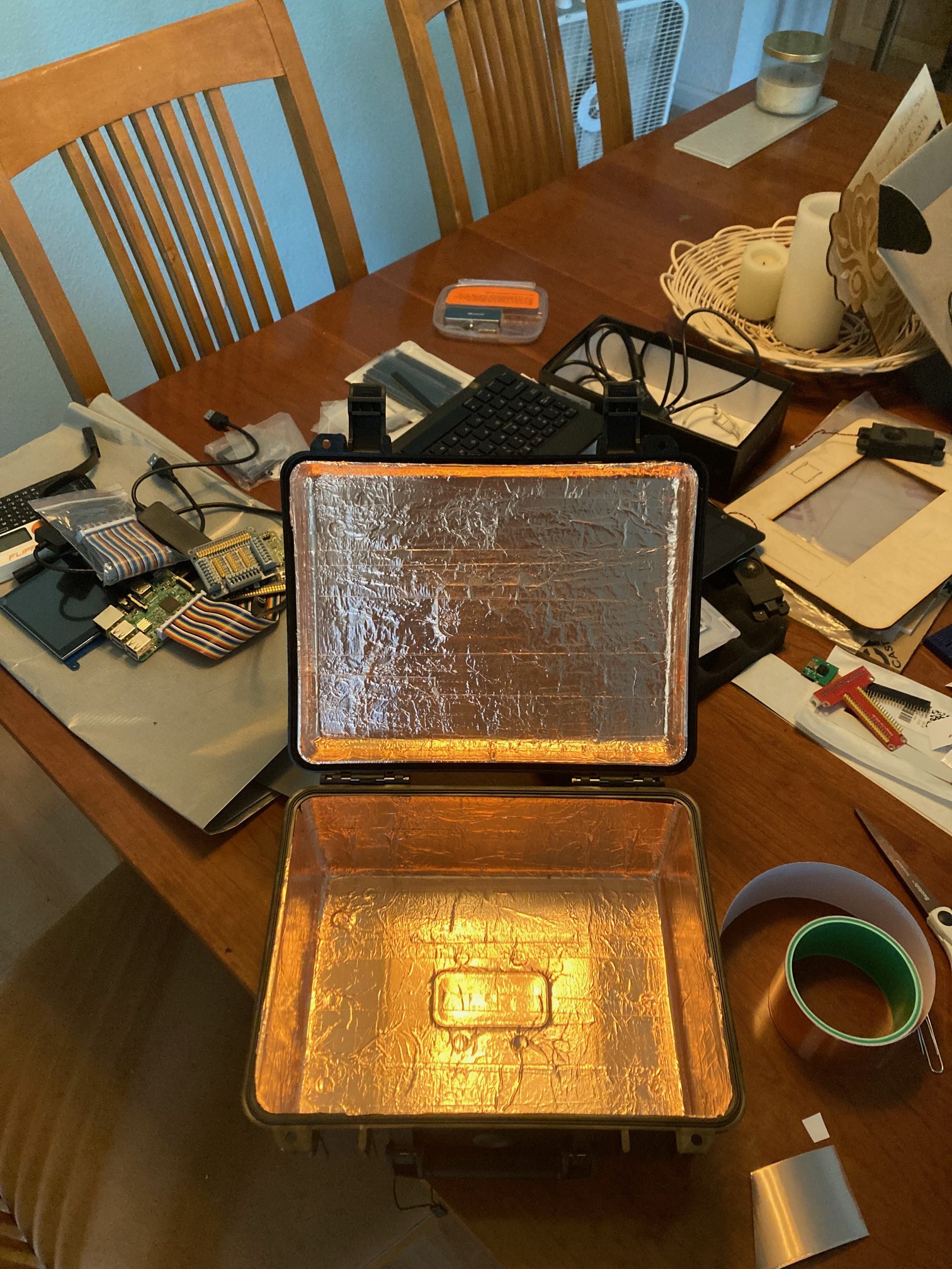
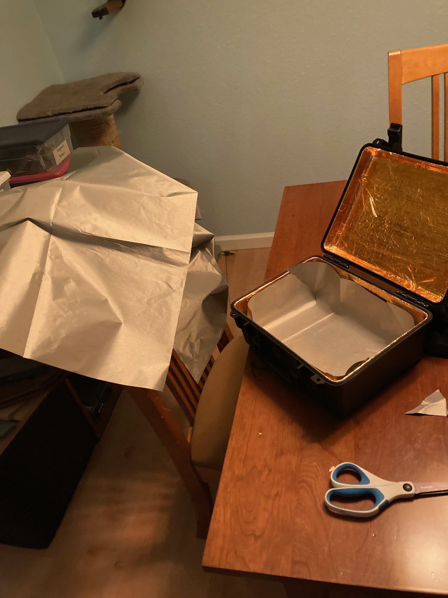
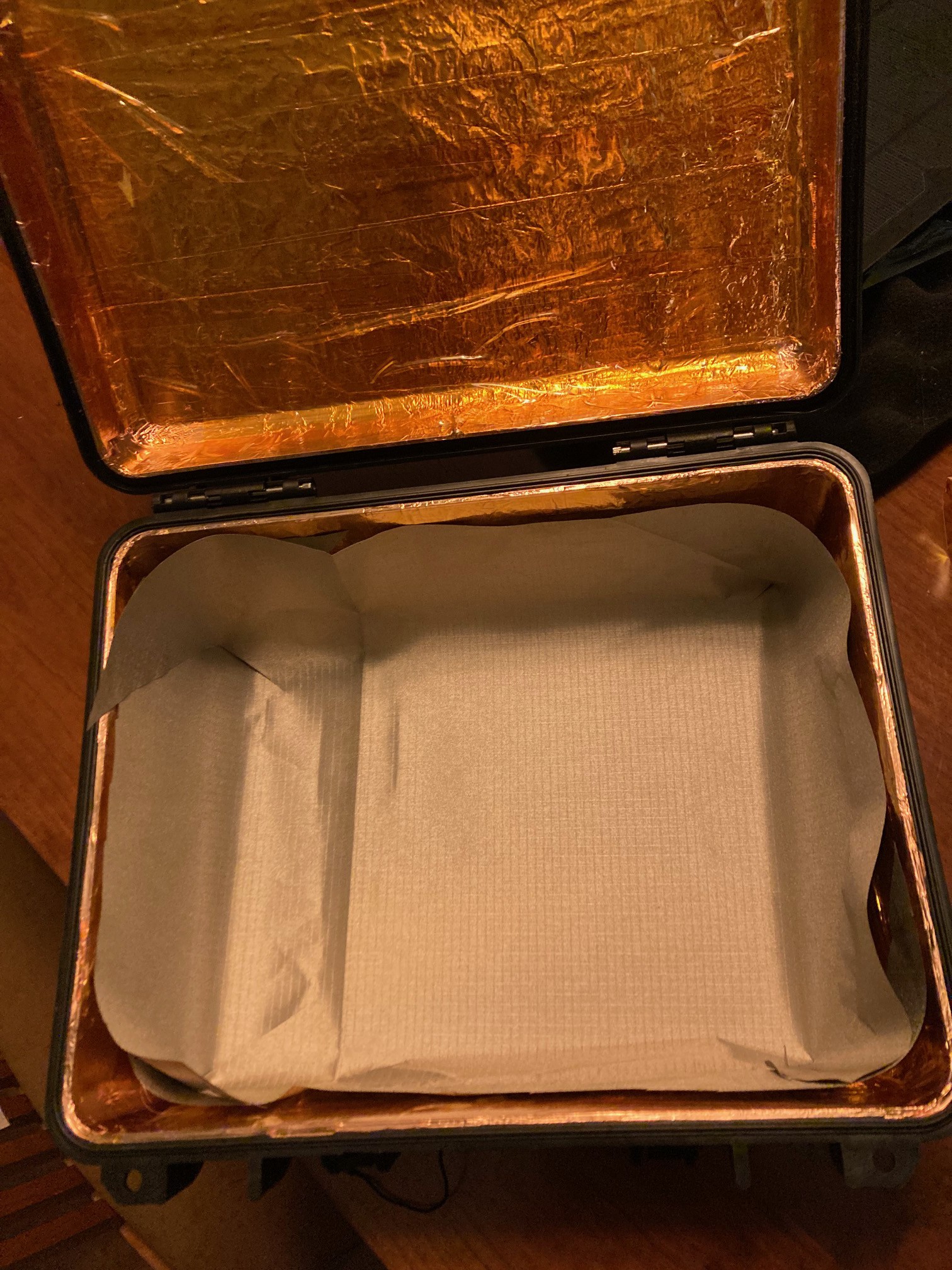
A layer of Kapton tape will go between the copper foil tape layer and the silver fabric layer to prevent any dissimilar metal interactions. The next pic shows a partially covered interior.
![]()
And finally...done with the Kapton tape. Now to ponder how to bond the shielding fabric.
![]()
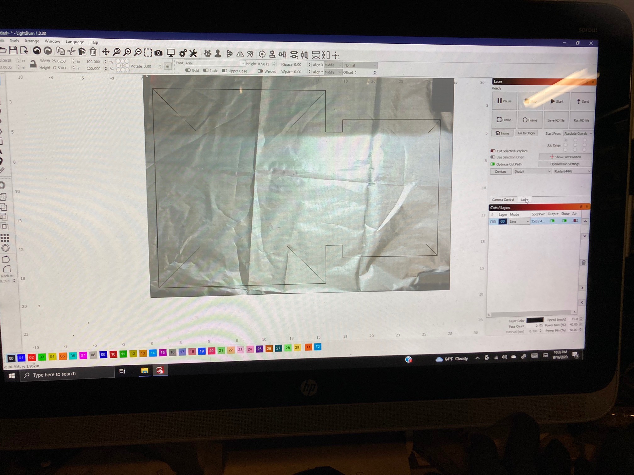
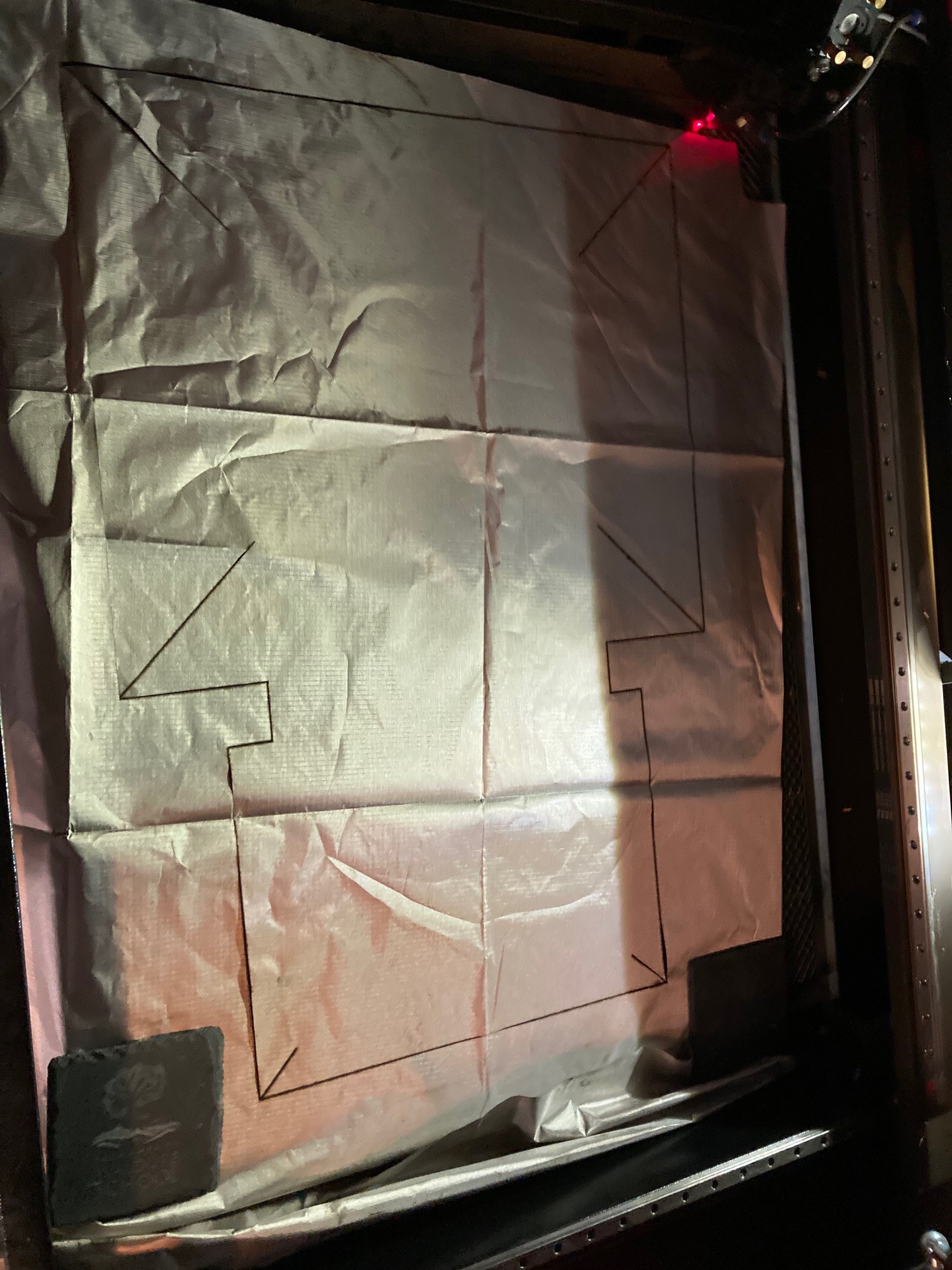
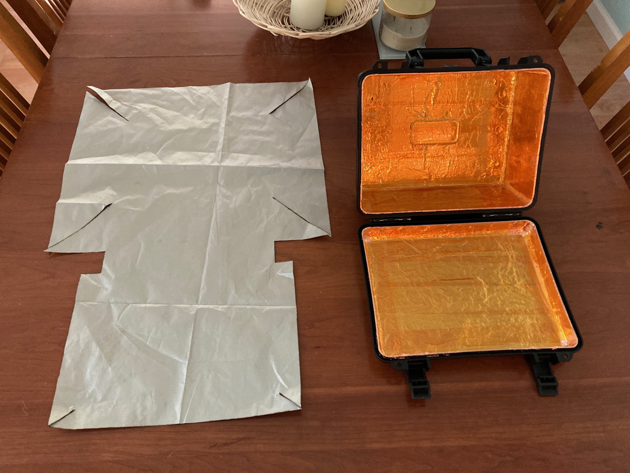
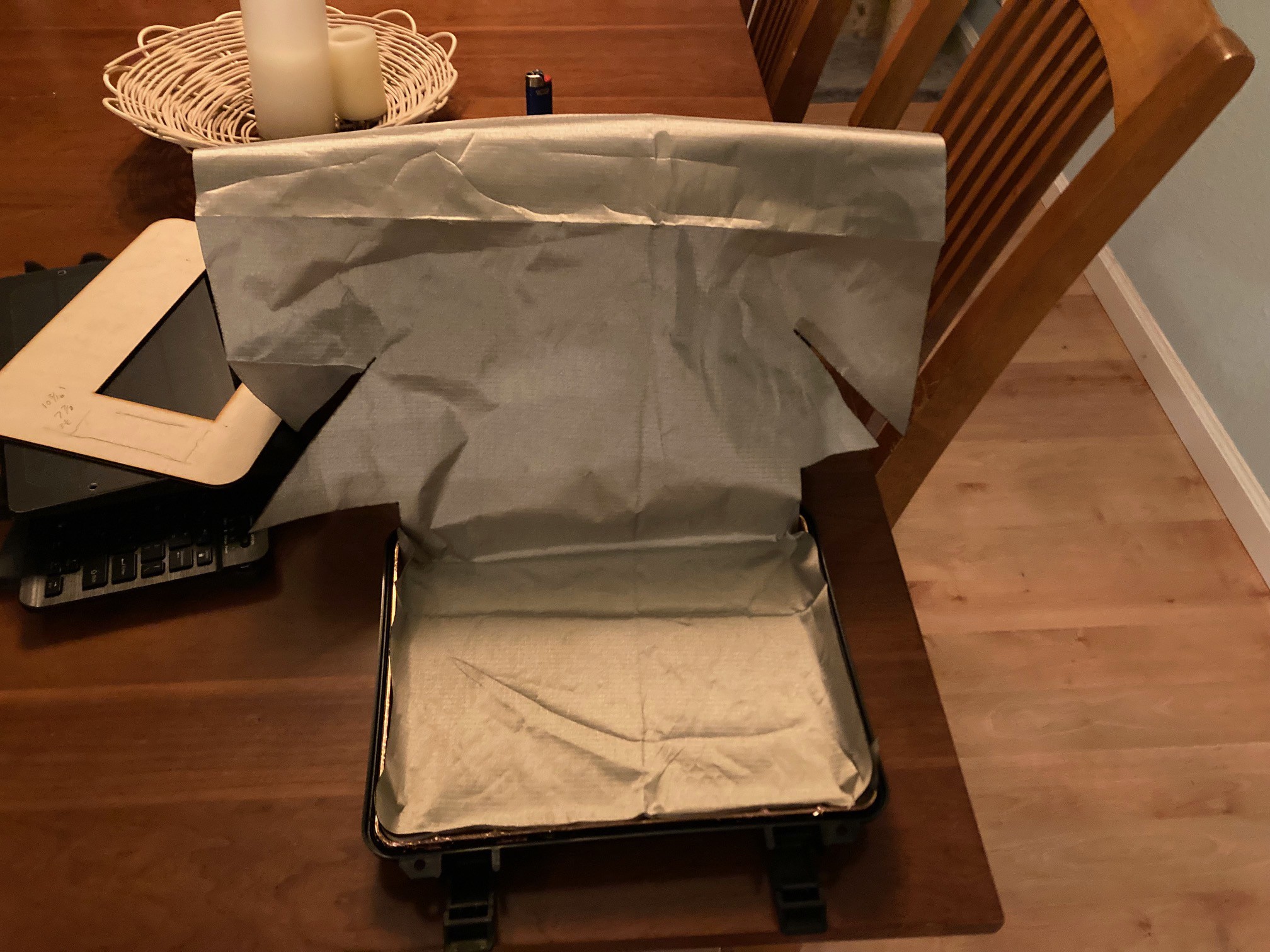
Cutting some test patterns of the shielding fabric and test fitting
![]()
test fit close up
![]()
![]()
![]()
![]()
![]()
-
3Functional Feature Design
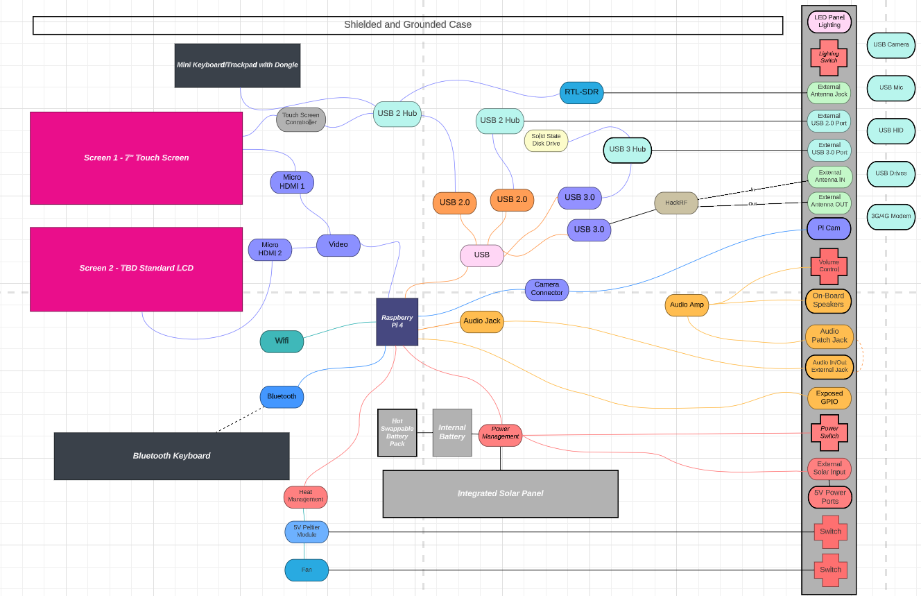
I started by visualizing what I wanted and then created a feature cloud of everything I wanted and how that mapped to the components I needed to account for and what needed to be exposed on the front panel. I created my desired feature cloud in Lucid chart. https://www.lucidchart.com/pages/
![]()
This was a kind of a visual inventory and forced me to think through these relationships. The grey bar on the right are all of the items that I envisioned being on the control panel. This was aspirational and a starting point. As I started to consider budget and space, things have been optimized and I've been removing things I couldn't support or didn't have room for. I'll update this as I get a little further into the 3D design which is also helping me to visualize the physical space constraints.
-
4More Research and some design...
So I say "More" research because if you are anything like me, you've wouldn't have gotten this far without having already done some amount of research. At this point though, you have the case, you have the feature goals, now the rubber hits the road and you start to suss out the details. Component cut sheets, 3D models, specs, ratings, compatibility, power usage, voltage, what's available off the shelf, what do I have to build myself, how are other people solving the same or similar problems...I also asked ChatGPT questions in areas I did not have domain knowledge and found it very helpful to aid in my research activities.
Grabcad has been a hugely valuable resource. Adafruit has great details on all of their hardware, 3D models and documentation of their software. Lot's of Youtube info on SDR hardware and software. Hackaday obviously with some serious sic builds. I've been more focused on hardware and hardware related concerns, there is going to be another wave of this for software which I have only just dipped my toe in so far...expect another step for that later on. :)
-
5Layout and Physical Design - CAD/CAM
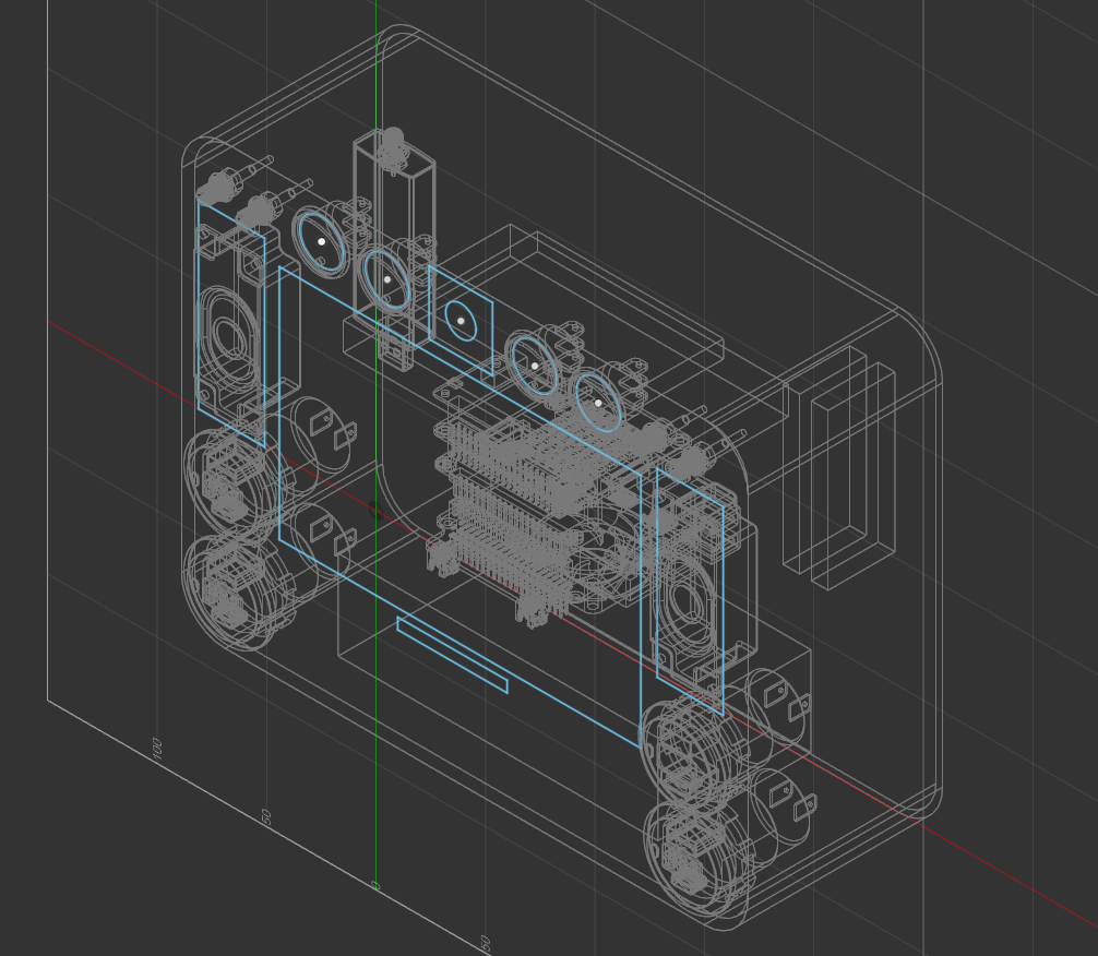
I use Fusion 360 for hobby projects so this was a good opportunity to put some of my skills to the test...to model this I used Fusion 360 which is a Parametric 2D/3D design modeler/editor from Autodesk. Fusion 360 is free for hobby use.
![]()
Using the measurements I took in Step 1, I modeled a placeholder volume that represented the interior of the case. I then used that virtual volume as the limits of my virtual interior. By placing virtual objects into that volume, it allowed me to start to assess available space overall, minimum depth needed, room for wire pathways, orientation for external ports and so on.
Once I have everything measured, placed and finalized; I'll model a frame that integrates the components into the volume and slides in and out of place. Details are still TBD on that front, stay tuned.
Everything but the kitchen sink cyberdeck
My cut on the iconic project build. I have the case, I have the PI, I have a vision. Let's see if I can get it done.
 Curtis Soldano
Discussions
Become a Hackaday.io Member
Create an account to leave a comment. Already have an account? Log In.