EDIT : To be rewritten
Project Logs :
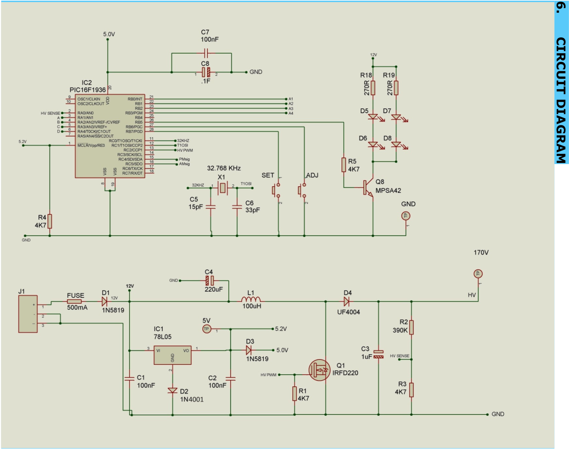
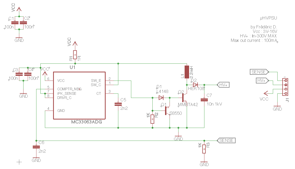
- First step : the schematic
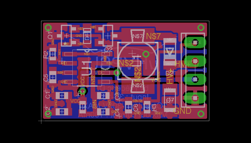
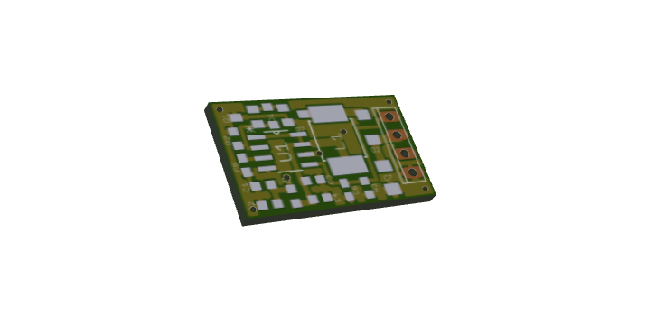
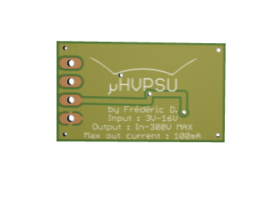
- Second step : the PCB
- Ordering PCBs
- Quick thing
- UPDATE : This project is not dead yet !!!
- v2.0
•
old description [
I was playing around with Nixie tubes, and I was using a 10$ HV supply kit on eBay to generate the 200VDC needed to power them.
My friend Manoel (@M.daSilva) uses an assembled module, which also costs 10-12$. It's a reasonable price, but I don't really understand why it's "so" expensive when you see the few components on it.
A few months later, I found a quite interesting website (link) made by Radu Motisan (Hackaday.io profile), which has a lot of projects involving High Voltage radio tubes, geiger tubes, etc.
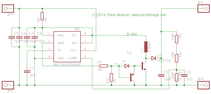
I came across a post with a really small HV boost converter, powered by a CR2025 battery (link).
This gave me the idea to make my own; the micro High Voltage Power Supply, or µHVPSU, for short.
My goal here is to make a small HV PSU that costs less than 5$, "labor" included.
The schematic is nearly entirely based on the one on the website, but I made some modifications (see project log 1)
Project progression : about 75%
If this project works, I will put a link somewhere where you will be able to buy the PCB directly on DirtyPCBs.
P.S.: I misread the MMBTA42 datasheet, so the maximum input voltage drops from 16V to 6V. For the next revision (V1.1) I'll probably use the STR1550, as V(eb) is equal to 9V, and the maximum V(eb) is 500V, which means that the maximum output voltage of the µHVPSU will be 500V !!
]
 Frédéric Druppel



 Greg Duckworth
 agp.cooper

 Radiolaria Lab
I think some of your math is wrong. It is not practically feasible to boost voltage that much with a single step boost converter. You need around 9V input to reach 170V on the output. 3V -> 200V, not going to happen. You need a tapped inductor to do that.