Close
0%
0%

EasyNixie

A simpler and safer way to drive nixies

Similar projects worth following
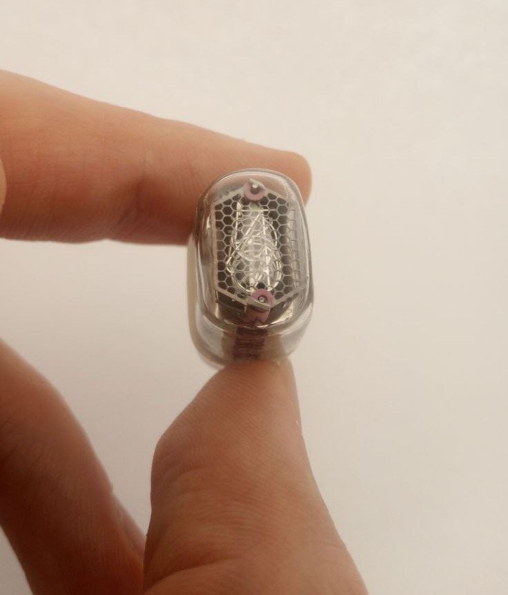
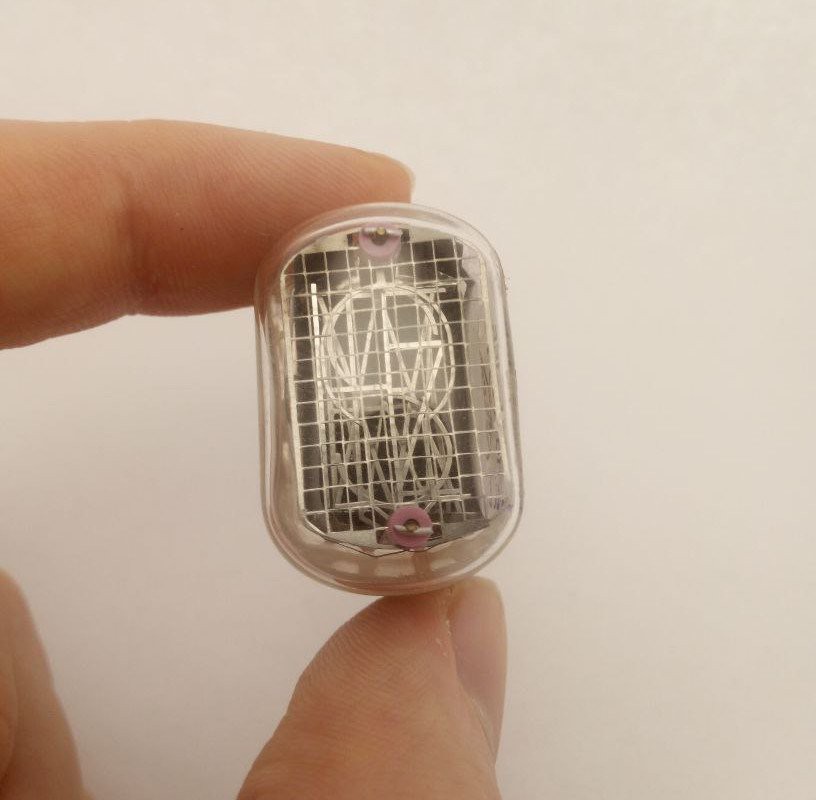
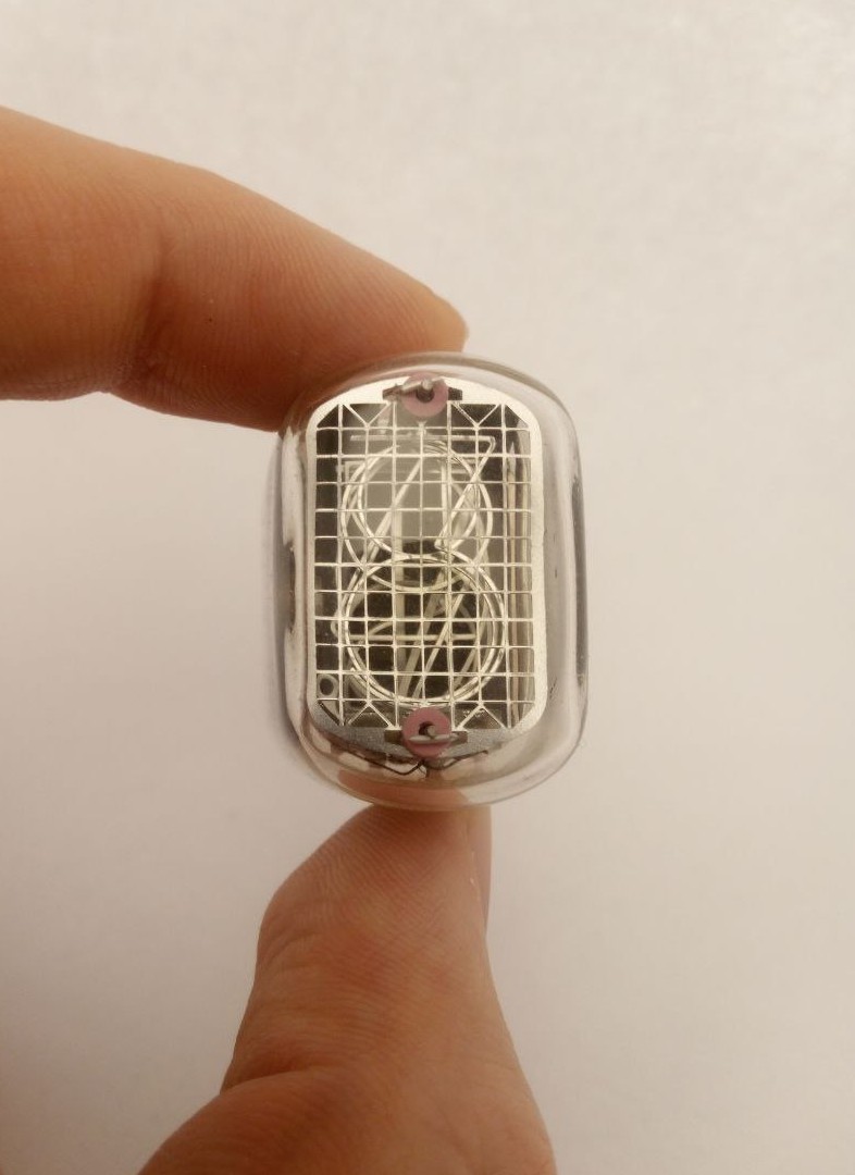
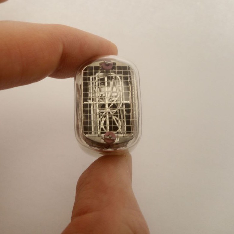
I have been fascinated by nixie tubes ever since I discovered what they are. So strange, so old school, so 'warm'. Unfortunately, they are also hard to control and can be dangerous if not handled properly. Definitely not a beginner's project. 'Of course', five years ago, when I started learning about electronics, I immediately decided to build something with them. And, I failed... I was working with a PIC16 MCU, but the code I created turned into a classic example of spaghetti code. It wasn't functioning properly, and as the winter holidays drew to a close, I decided to set my experiments with nixies aside for a while.

Five years have passed since that moment. I've learned a lot, and I'm now prepared to confront my old nemesis. Remembering how challenging nixies were for me, I decided to make something that would make life a little easier for all the nixie enthusiasts.
Checkout the Kickstarter Link.

Ok, lets dig in details a little bit...

Three hardest things about driving nixie tubes are probably:

  • High non-standard voltages - Nixies require 180VDC
  • Many control pins - Each digit has its own cathode, which brings 11 digit control pins and comma control pin
  • Non-standard pin positions require special holder sockets

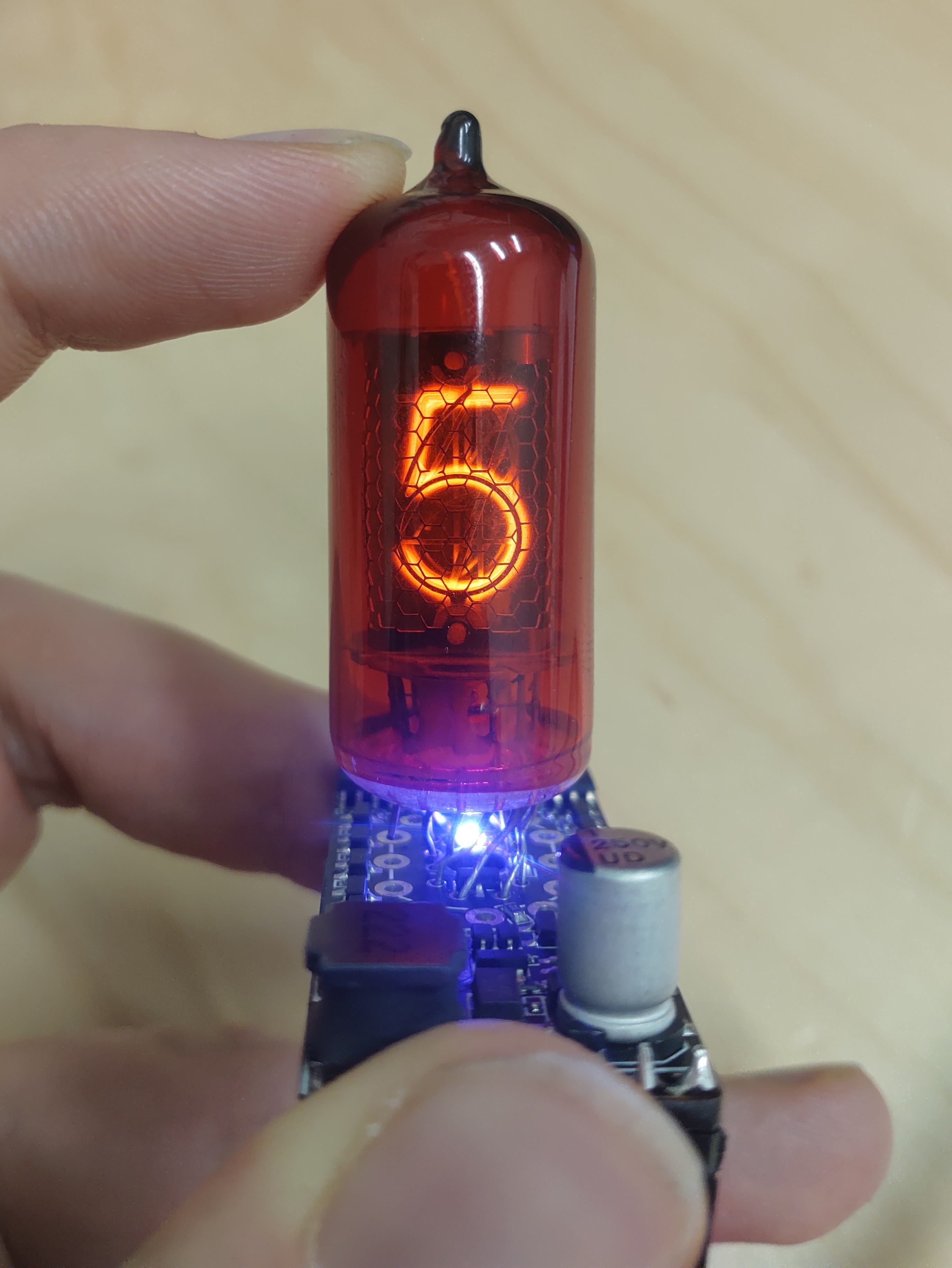
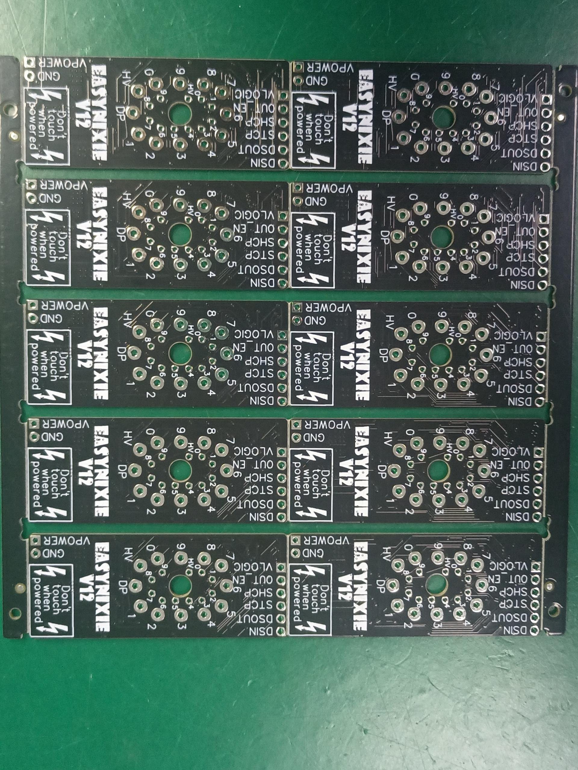
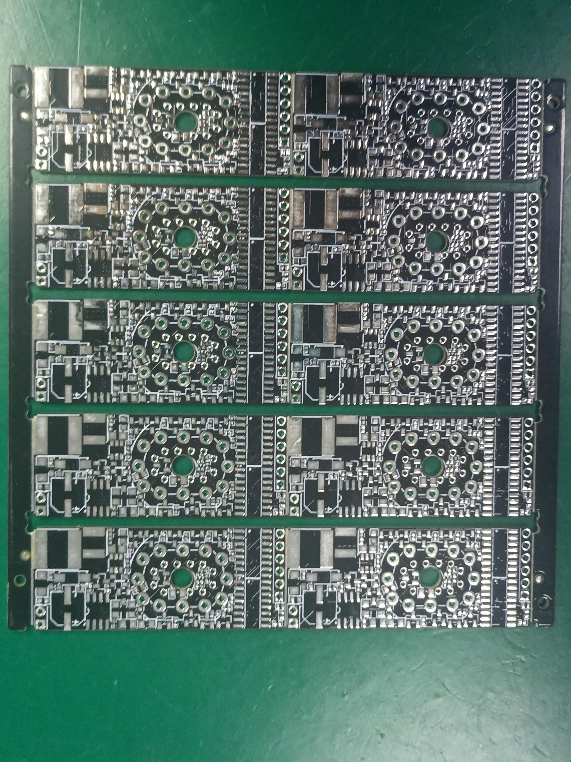
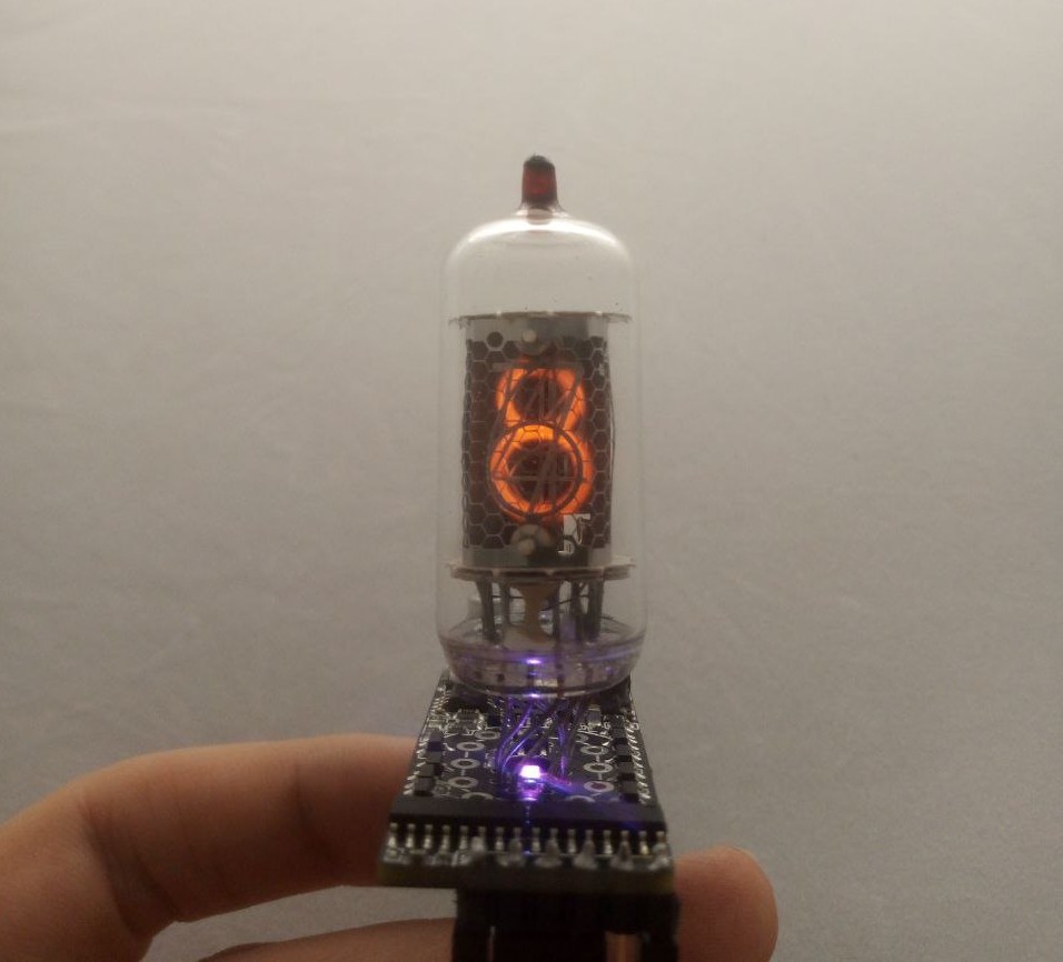
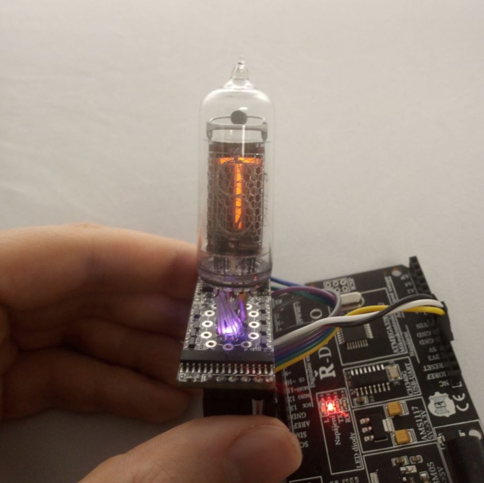
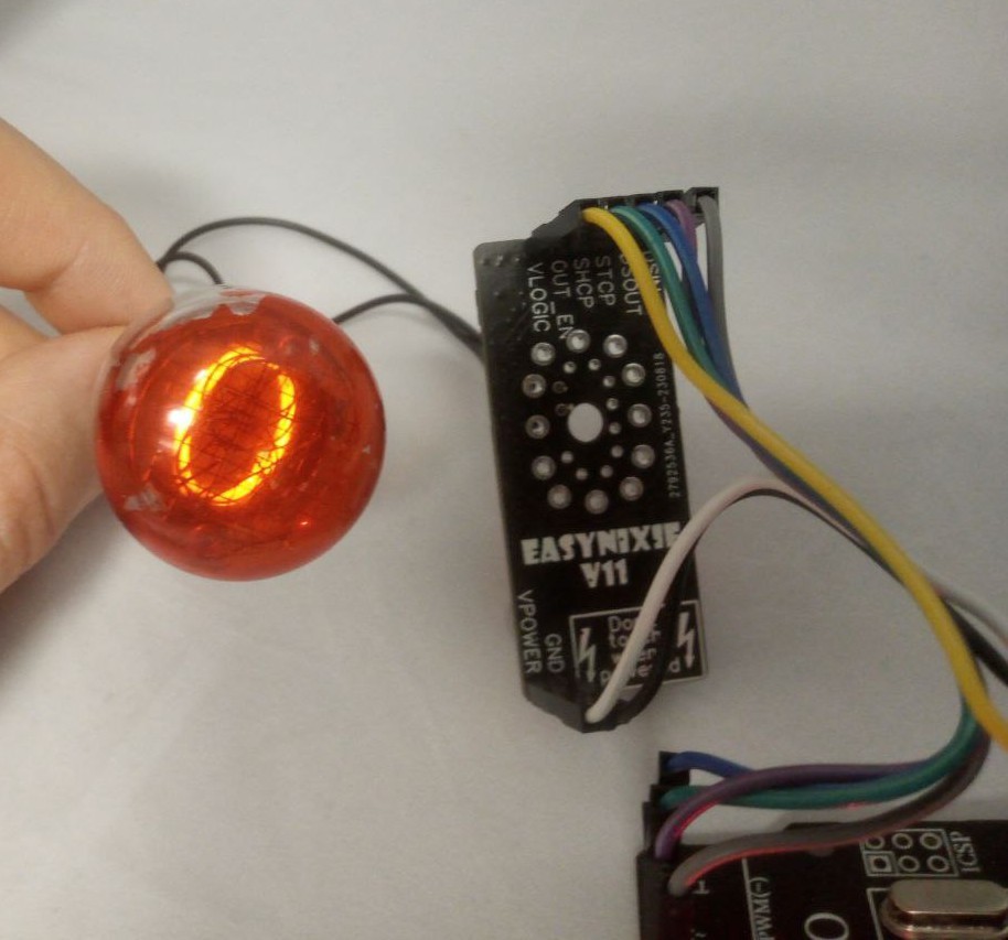
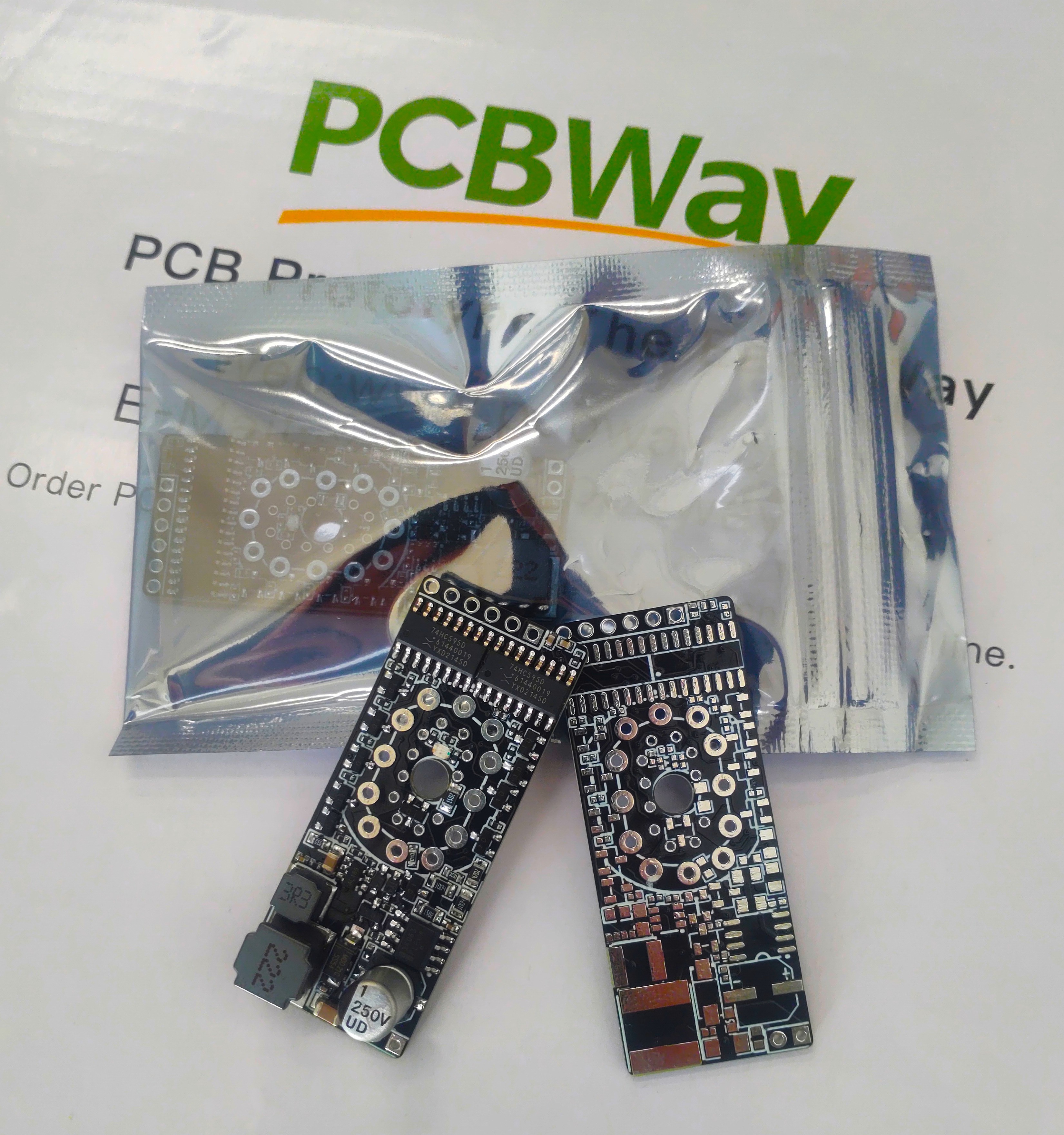
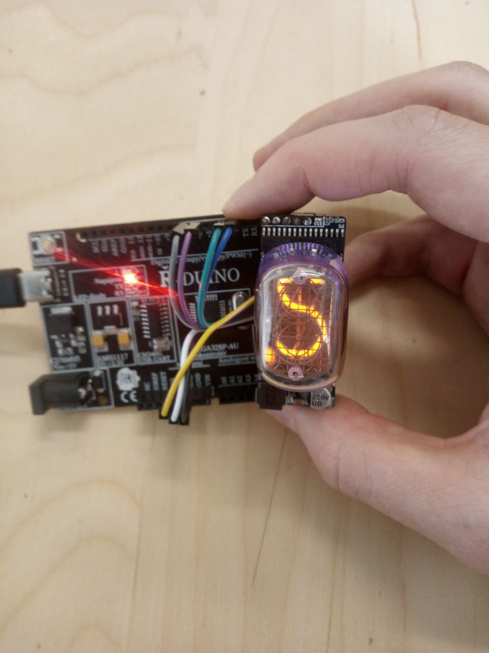
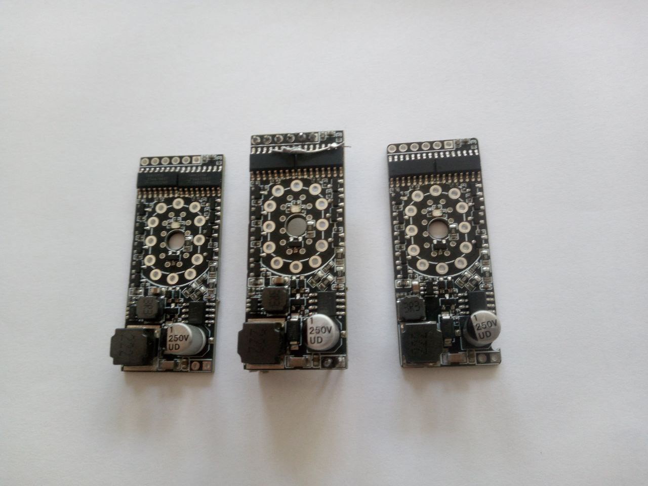
The goal of this project was to build a ‘smart socket’ that handles these problems. The designed socket has step-up 3.3V-180V converter on-board and 2 shift registers to control all the pins and rgb leds. Here is how the final design looks like:
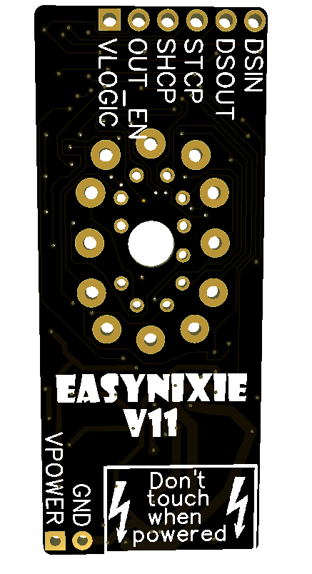
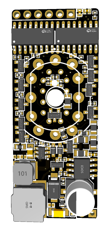
And the schematics:
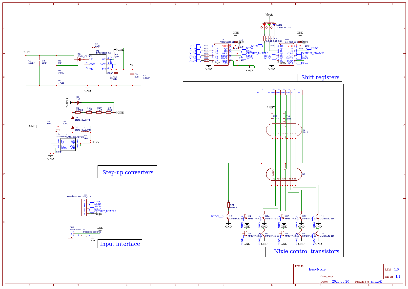
The main blocks are:

  • Step-up converters - this part does 3.3->180V conversion. The conversion is done in two steps: Vin->12V and 12V->180V. The Vin to 12V convertor is not as interesting, as the connection is pretty standard and done according to the datasheet. The 12V to 180V conversion circuit is a little more complex. The output voltage is set using the feedback pin and resistors R1, R11, R10, R13.  3 resistors(R1,R11 and R10) are used instead of one with the bigger value because of the max voltage for 0402 package, which is usually 150V. The same goes for the two diodes(D4 and D2). This convertor 'duo' can't deliver much current (about 4mA max), but it is enough to power one tube. Because of that, it is definitely safer than having one high power convertor for multiple tubes. The convertor 'duo' also have voltage enable pin, which turns it on.
  • Input interface - Just some control pins with a 500mA safety fuse. Safety fuse is a little bit redundant, assuming the step-up convertors can't deliver more than 4mA anyway, but too much safety never hurt anybody.
  • Nixie control transistors - high-voltage MMBTA42 transistors drive the nixie tubes cathodes. There are two nixies displayed on schematics because there are in-12 and in-17 sockets connected in parallel. Since in-17 is super tiny,  its socket also has additional current limiting resistor. All the supported tubes are : In-12a, in-12b, in-15a, in-15b and in-17
  • Shift registers - classic 74hc595s are connected daisy-chain style and control high voltage transistors with only 3 control pins. Of course daisy-chain configuration allows connecting multiple EasyNixie modules.

View all 8 project logs

Enjoy this project?

Share

Discussions

jcomeara wrote 04/21/2024 at 07:20 point

Lovely work, but just wondering if these would be compatible for IN-16 tubes.

  Are you sure? yes | no

allexoK wrote 05/03/2024 at 10:14 point

Hi jcomeara, sorry for the late response, must have missed you comment. I haven't tested them with IN-16, but they should work out of the box, assuming the connections are correct.(IN-16-ANODE->EasyNixie-ANODE, IN16-CATHODE-1->EasyNixie-CATHODE1, and so on)

  Are you sure? yes | no

Ken Yap wrote 08/27/2023 at 04:53 point

Nice project. 👍 I too like the look of nixies and glowing gas in general. Have a look at #Modularnixie for another way to drive nixies that only requires one 8-bit shift register per digit.

Incidentally the film Oppenheimer has an anachronism. Nixies appear in the countdown scene but they weren't invented until the '50s.

  Are you sure? yes | no

allexoK wrote 08/27/2023 at 10:06 point

Thanks, I have just checked it out, the nixie driving scheme is very smart! And the schematics of #Modularnixie looks neat and clean. The nixie type choise(cd71) is quite interesting, I haven't seen modules that can drive this type of tubes... Japanese tubes in general are rarer and sometimes doesn't have alternatives (like super beautiful gigantic CD47).

I also noticed that thing in Oppenheimer...

  Are you sure? yes | no

Ken Yap wrote 09/04/2023 at 08:10 point

Actually I didn't have a choice. They were what I had lying in my parts box for many years. Recently I extracted nixies from an old Sharp calculator I saved from a flea market for $1 and they are NEC CD89s, so I have adapted the layout for that and will produce a batch of PCBs later this year. (Much as I like nixies, I will not spend money buying NOS, since what I have will keep me occupied for a while.) The PCB design needs to be adapted for each tube model. If a socket is involved that needs to be designed in too. My circuit design is only a starting point.

  Are you sure? yes | no

aymen wrote 08/24/2023 at 20:43 point

good work

  Are you sure? yes | no

allexoK wrote 08/24/2023 at 20:54 point

Thanks!

  Are you sure? yes | no

Similar Projects

Does this project spark your interest?

Become a member to follow this project and never miss any updates