Denys Zaikin
-
Measurement with NanoVNA V2 - SAA-2N
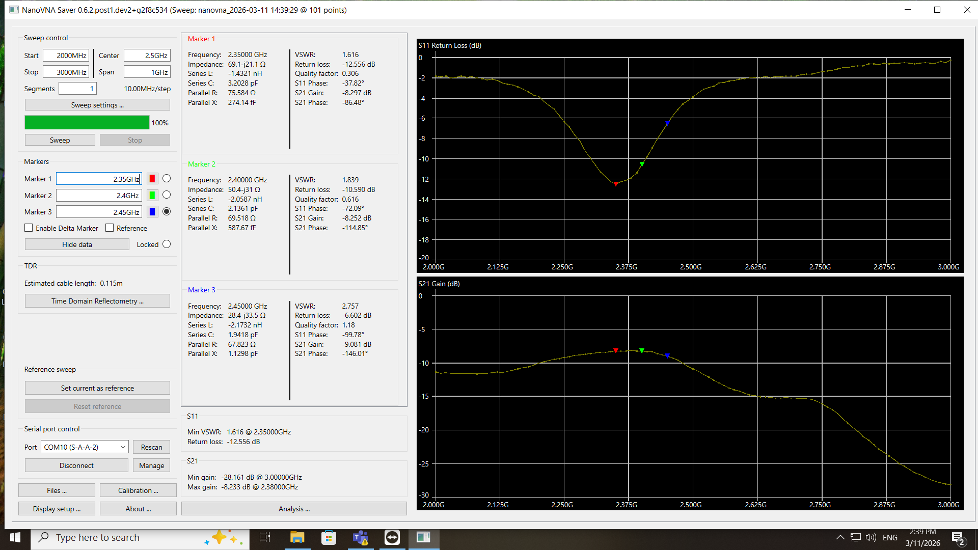
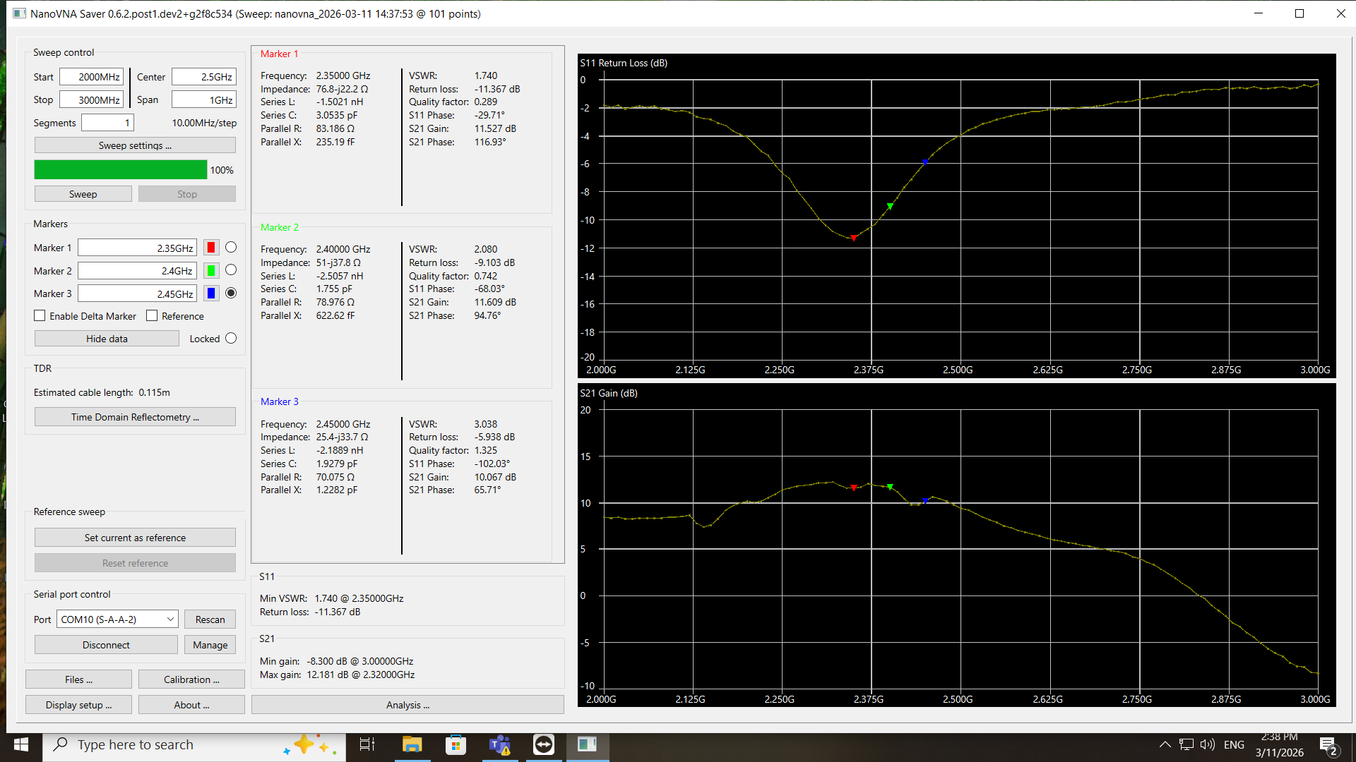
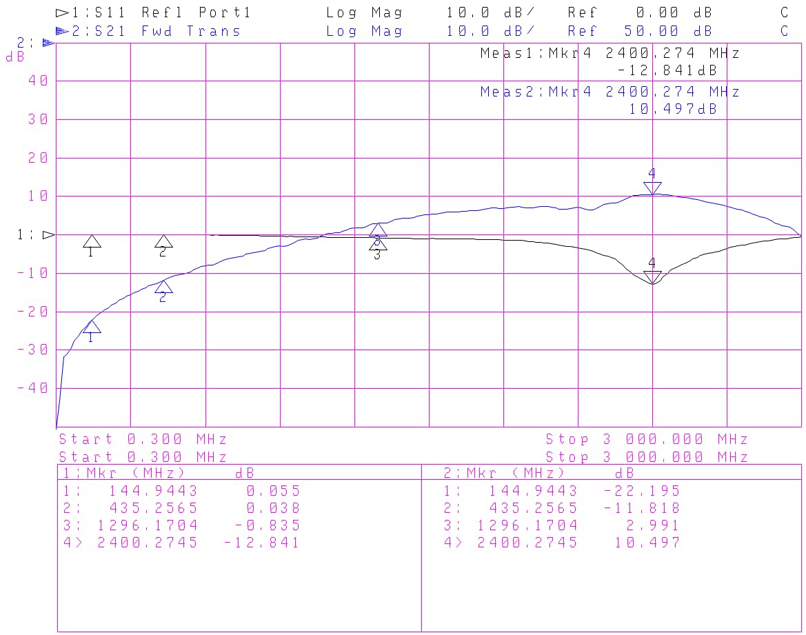
02/25/2026 at 21:21 • 0 comments- I needed to change the central frequency a little to 2.4 GHz, so I implemented 1.1pF in input side of the RF2126 module instead of 1pF for C1 and C2. To get 1.1pF, two 2.2pF 0805 in series were used.
- 20 dB attenuator at the output of the RF2126 module:
![]()
- no attenuator at the output of the RF2126 module:
![]()
-
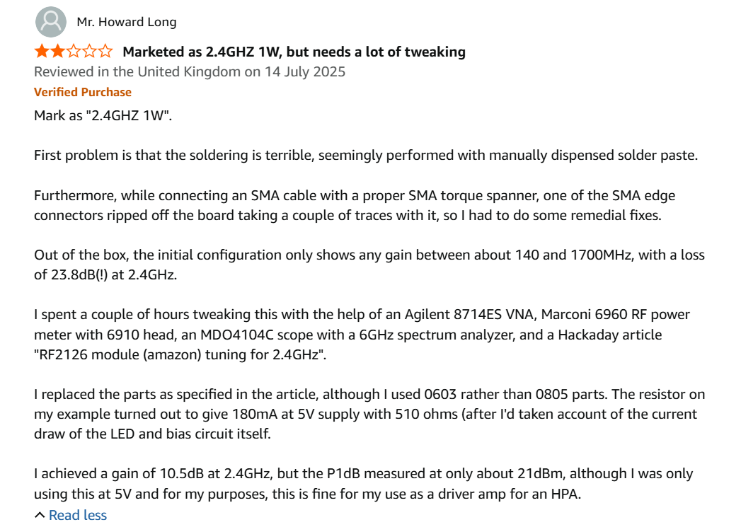
Somebody's review and feedback
02/16/2026 at 11:48 • 0 comments -
Second RF2126 module modified
09/08/2023 at 20:30 • 0 commentsNotes
- The second module was modified with the same modifications. Looks OK.
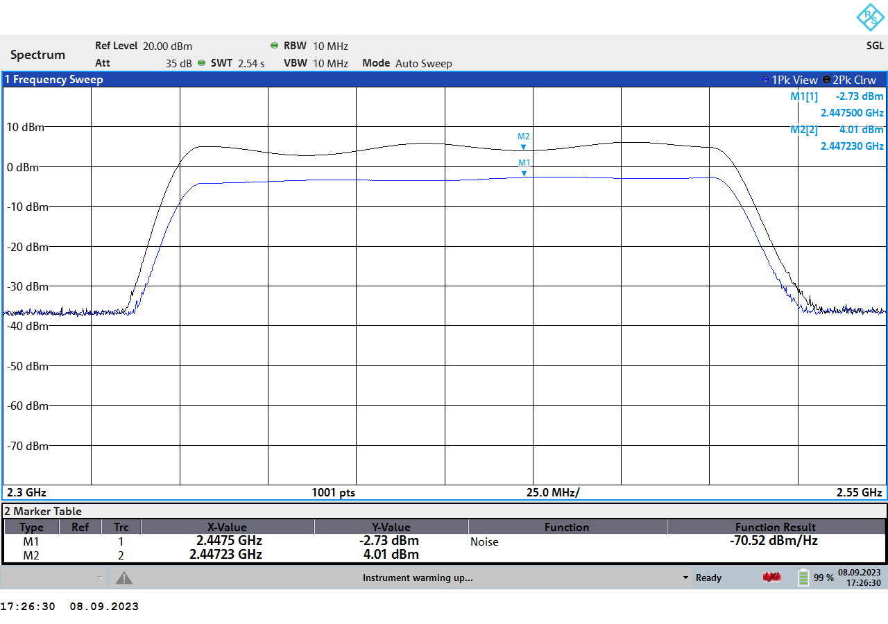
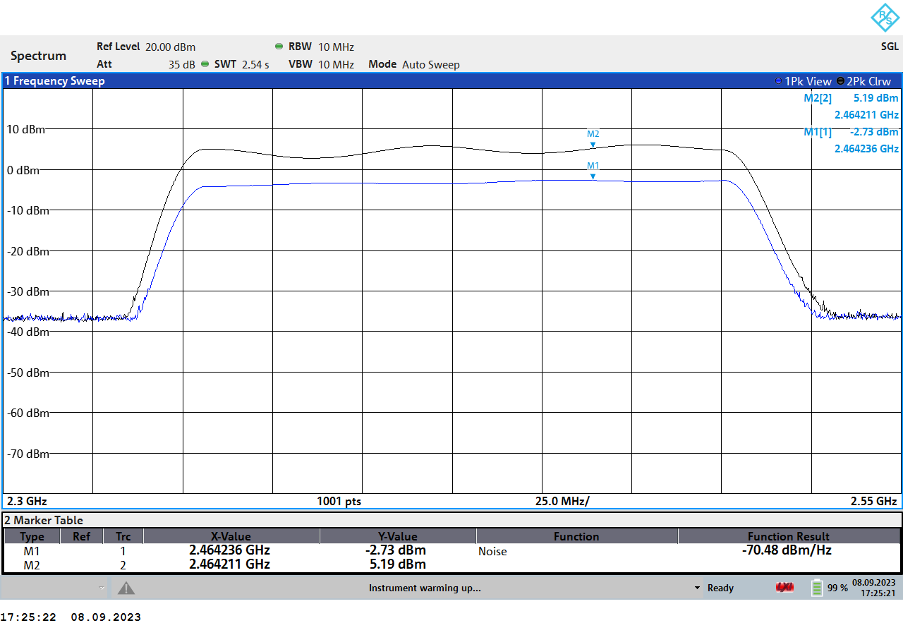
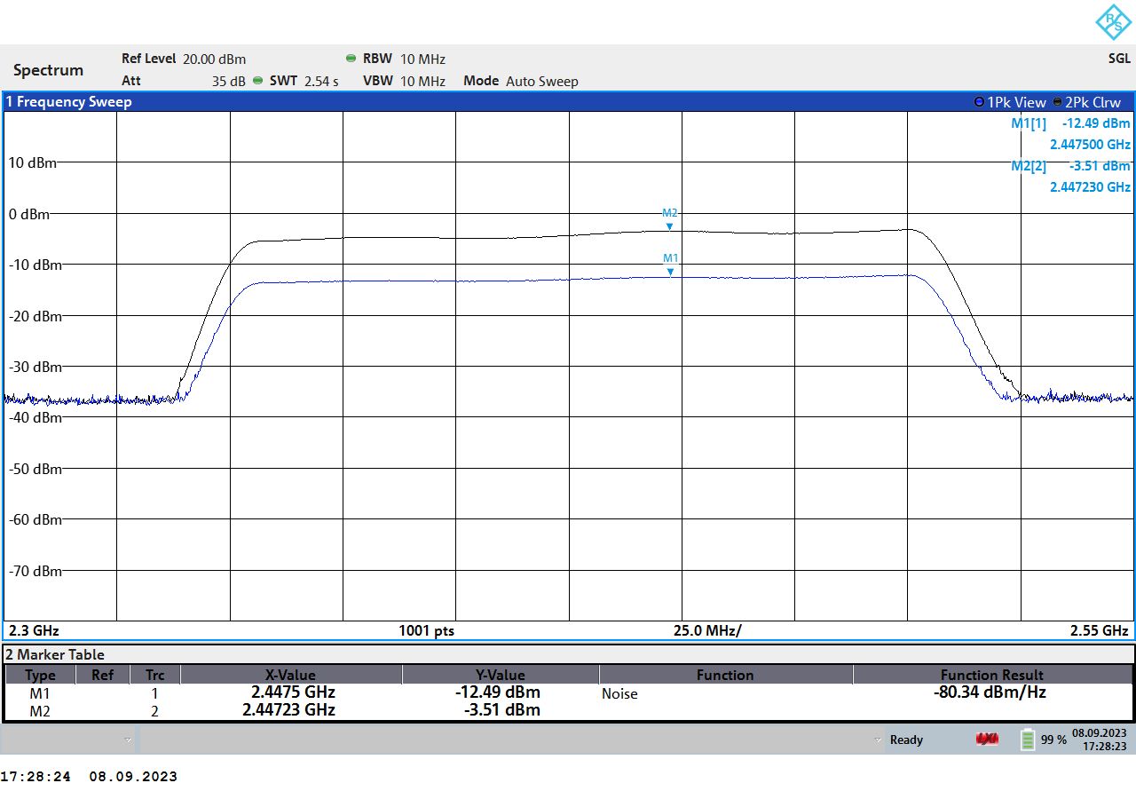
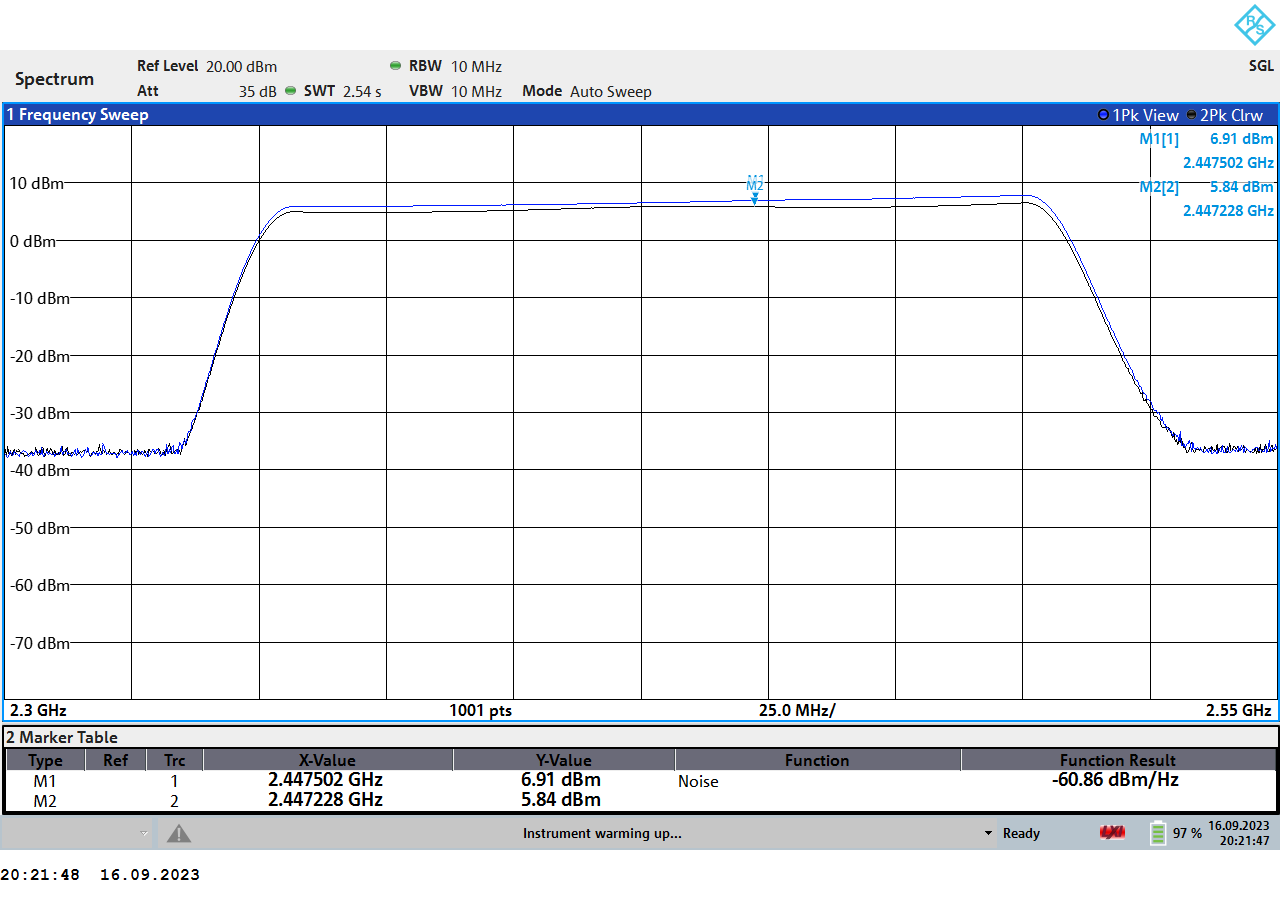
- 10dB attenuator at RF2126 module input improves gain flatness, so seems like the signal generator source impedance is not perfectly equal to 50 Ohm. See the log for the second module modification results.
No attenuator at the input, only a 20dB attenuator at the spectrum analyzer input
![]()
![]()
10dB attenuator at the input of the RF2126 module
![]()
Short/long cable comparison
- 20dB attenuator at the input of the spectrum analyzer.
- The cable length is 150mm (Wuerth RG174/U 65503503515303) from the generator to the input of the module.
- Comparison between 150mm and approx. 1m (RG174) lengths on the output of the module.
- Seems like 1m cable had approx. 1dB of losses.
![]()
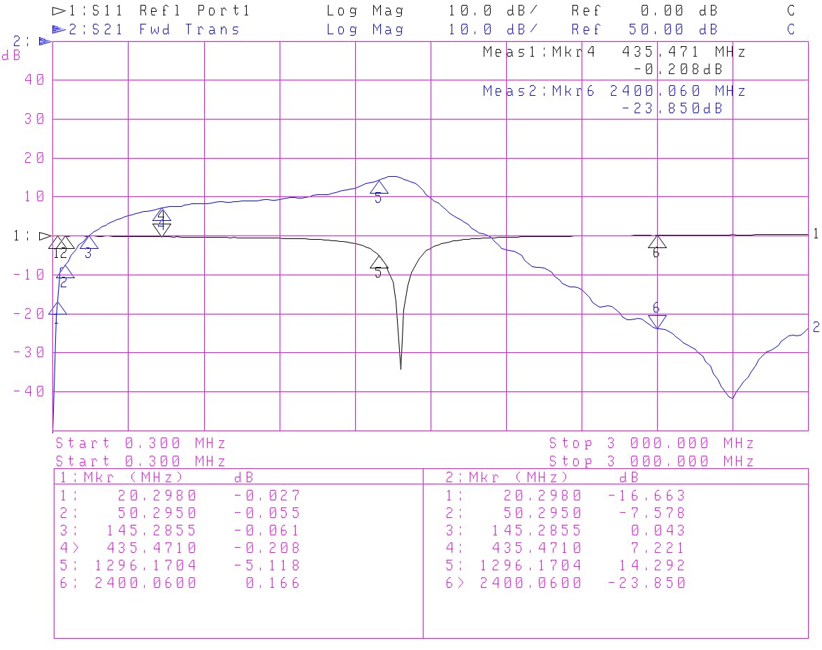
RF2126 module (amazon) tuning for 2.4GHz
RF2126 module received from Amazon. It did not work for 2.4GHz as announced. So tuning was performed.