-
Of PCB assembly quality control...
04/05/2024 at 15:06 • 3 commentsIt now has been about 18 months since I have started designing and producing the Central Scrutinizer. It has been a fun trip into building something physical, as opposed to just writing software.
I have learned a lot in the process (see my first log entry), and I'm really glad that I managed to build something that people do find useful.
However, a constant source of frustration has been the PCB assembly process. I only own a basic soldering iron, and my eyesight is not what it once was, so while I'm happy to assemble the through-hole stuff, I leave the SMD work to the PCB shop, aka JLCPCB. The whole project is configured to make it super easy to upload the design to their website and get working boards by mostly accepting the proposed default options.
I'm also not a huge operation, far from it. I produce boards in small batches (about 10 to 20 at a time), giving most of them for free to fellow open-source developers, and selling whatever is left on Tindie. This makes the buyers indirect sponsors of the open-source projects that use the boards, something I quite like. I don't make any money out of it, other than the odd beer with fellow hackers.
So it's all good, Sort of. What really gets me is the poor level of quality control that gets applied to the produced PCB. And poor doesn't quite describe it.
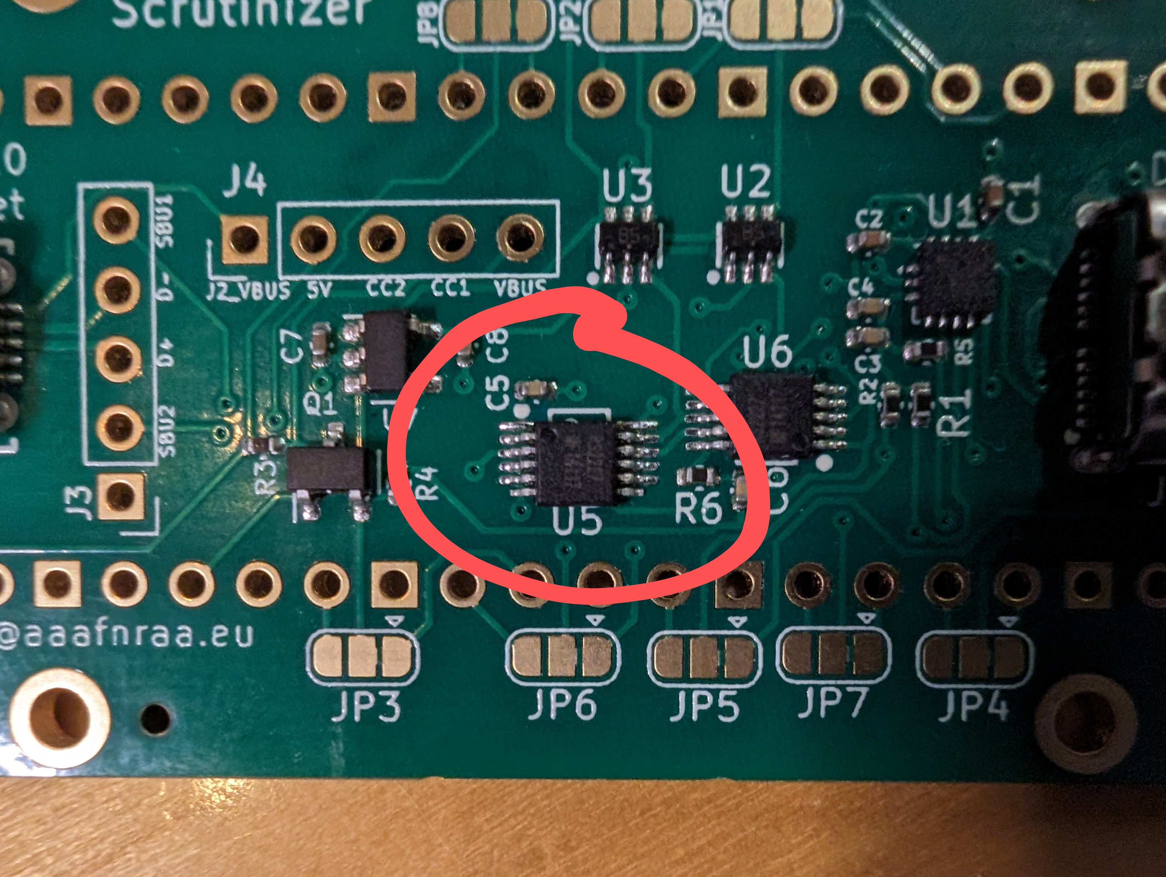
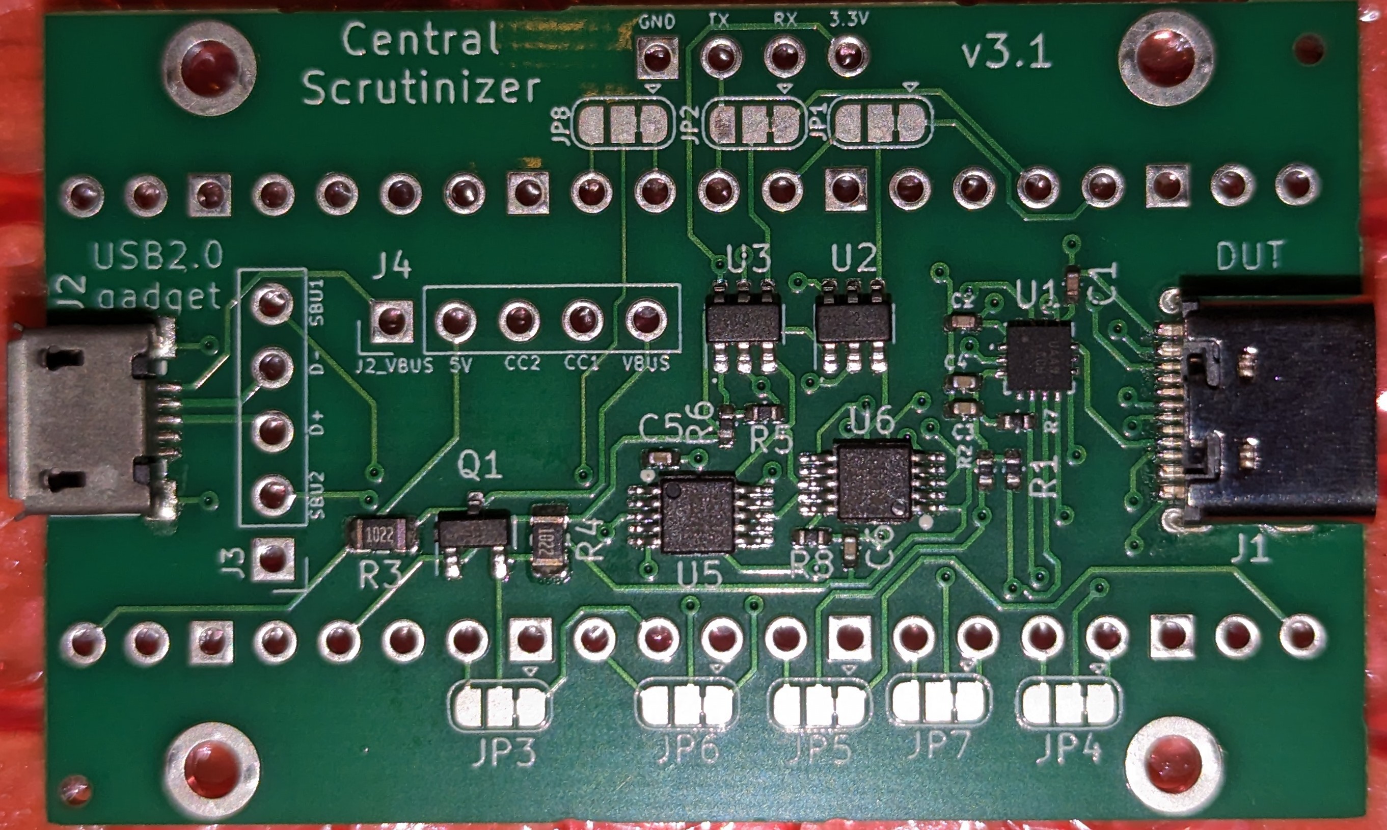
Here's the latest example:

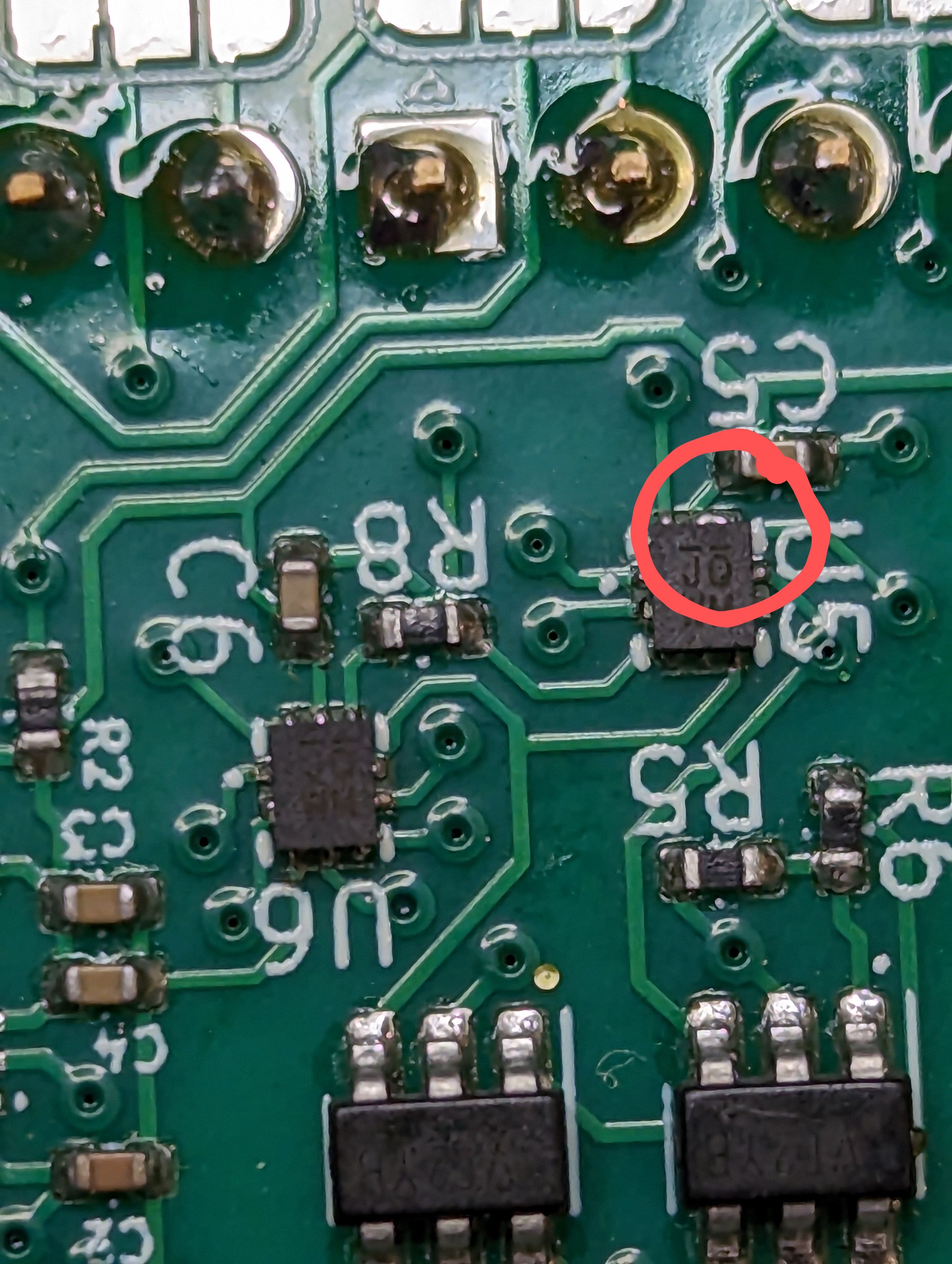
U5 is off. Not a bit off due to the component having drifted. It is exactly off by a whole pin. Something that any automated checking should spot immediately. And that's the issue. I'm pretty sure that given the rock-bottom price for the PCBA process, there isn't any margin left for actual quality control. So whatever crap that has been produced ships.
I've seen other similar issues, such as micro-USB connectors soldered at a funny angle, solder bridges and the odd dead component. For each of those, that's another board on the scrap pile. The planet thanks you. Not. Maybe I should invest in rework equipment...
Frankly, I'd happily pay significantly more for a reliable service with an ordering procedure as good as JLCPCB's. If you know of any, please let me know! I wonder how other people with my level of experience (close to zero) and equipment (similarly null) cope with this...
On the plus side, I've grown a solid enough test procedure, so I'm able to spot a bad board within a few minutes, and only ship the good'uns. I guess that's as good as it gets for an outcome.
-
M3, baby!
11/29/2023 at 20:59 • 0 commentsAs I found out today, the Central Scrutinizer is working out of the box on a M3-Max machine (and no, that's not mine):
https://oftc.irclog.whitequark.org/asahi-dev/2023-11-29#32702519;
I guess the good folks in Cupertino had no reason to change something that was working just fine!
-
Shape of things to come?
11/19/2023 at 12:27 • 0 commentsPeople who know me know that I don't really care about non-ARM architectures. I have been involved with it for a long time, and I'm yet to be excited by what has been coming from the other side of the fence (on the other hand, if you know of a new CPU architecture that doesn't repeat all the combined mistakes of x86+ARM+Power, please let me know).
That was one of the reasons to pick the RPi Pico as the uC for the Central Scrutinizer: an architecture I was comfortable enough with and can debug easily.
The same people also know that my OS of choice is Linux. I have been doing kernel stuff for a few decades, and this is the only OS I have used since 1993. Yeah, it's been that long.
Of course, picking the Pico meant that running Linux (*real* Linux, not uC/Linux) was out of the question. And for something that is essentially a set of state machines, it really doesn't matter much.
But then I saw this. The form factor is of course a direct nod to the Pico, but the characteristics are on a different scale: a 64bit CPU that is capable of running Linux, plenty of peripherals (including Ethernet), and a price that is close enough to that of the Pico that I start thinking of new possibilities... What if, instead of plugging the CS board into a console server, the CS was becoming *the* console server? And make use of the MIPI interface to do HDMI capture? Does anyone else think "full BMC"?
Of course, people paying attention will say "but this is a RISC-V CPU, what's wrong with you?". And they'd be right to ask. But maybe that's the sort of incentive I need to start looking at other architectures... ;-). And if you know of an interesting arm64 board with the same form factor, please shout!
Now, this thing is as far as you can imagine from being usable. There is a v5.10 BSP for it, which I am not going to touch with a barge pole (it mandates fetching unknown x86 binaries and running them locally, which isn't going to work anyway on my arm64 box). So I've started looking at the upstream support for it, and as of v6.7-rc1 we have interrupts, timer and UART working. Nothing else. Not going to ship anything with it any time soon.
But I definitely like the idea of it, and I plan to spend some time improving the upstream support. Maybe in a year or so, I'll be able to get to the point where the firmware for the CS is only a userspace process, and nothing else. That'd be cool... and would open the door to more interesting experiments!
Stay tuned!
-
I didn't have this in mind, but...
11/17/2023 at 14:32 • 0 commentsIt happened a while ago, but I thought I'd mention this hack on top of my own hack:
Note that I'm not affiliated with this in any shape or form, other than being pleased to see someone making an unexpected use of it!
-
Everything looks better in gold
11/01/2023 at 18:06 • 0 commentsA couple of weeks ago, I ran out of Central Scrutinizer boards. Between those that went on Tindie and the ones that I handed to fellow developers, that's about 50 boards that I distributed. Not bad for a pretty niche project!
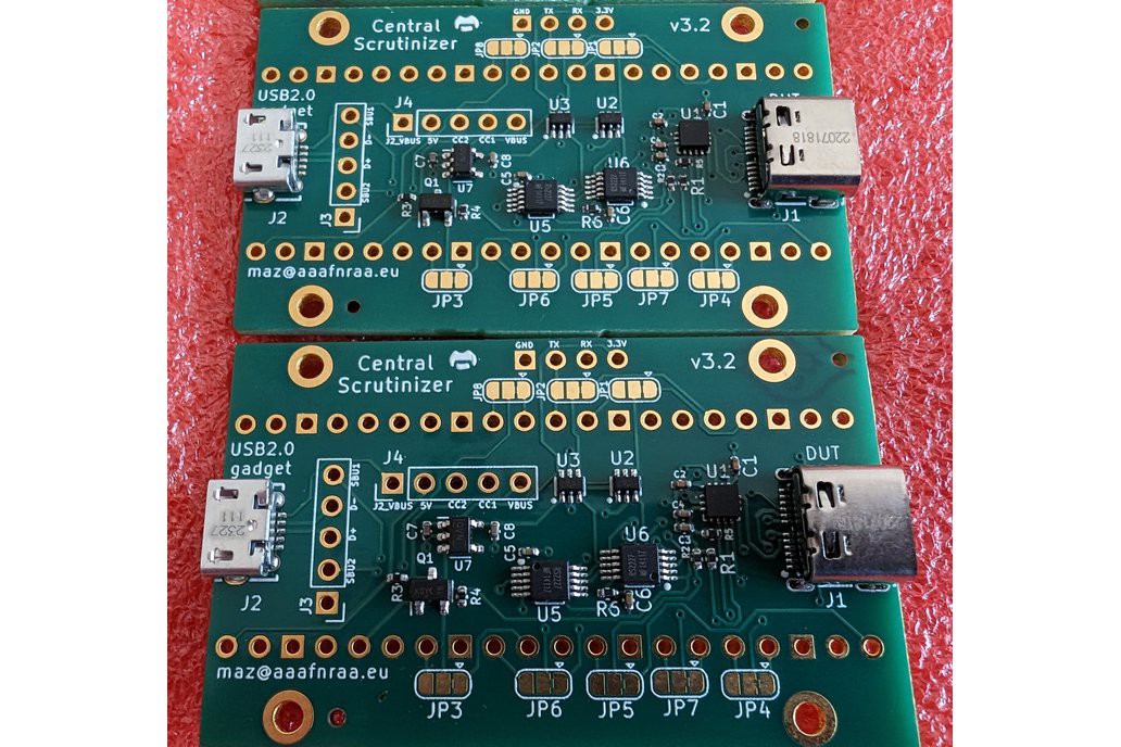
I hesitated making another run, as I'd prefer to see people building their own. But since I kept getting requests, I ended up producing another small run of v3.2 boards. This time using the ENIG process instead of the standard HASL that I used so far. So instead of the silvery and slightly bumpy finish, I get these gold-colored and super-flat pads.
It doesn't seem much, but it makes quite a difference at assembly time. Soldering them becomes almost an enjoyable experience!Other than that, they are still the same! I took this opportunity to retire my last v0 and v1 boards, and treat myself to some quality gold stuff! I'll still maintain the firmware for these early revisions though.
-
Behold the new test jig monster...
10/26/2023 at 19:49 • 0 commentsIf you have read my first (and way too long) log entry, you will be familiar with my first attempt at building a test jig, which looked like this:
Not exactly pretty, but functional enough: slap a board to be tested on top, secure it with the bolts, and let the Pico that lives underneath do the work. I was able to test a number of boards this way without having to solder anything.
However, this is a one off, and I thought I'd build something a bit less hackish. Also, I would like to be able to test the dual-board setup, which requires to be more inventive.
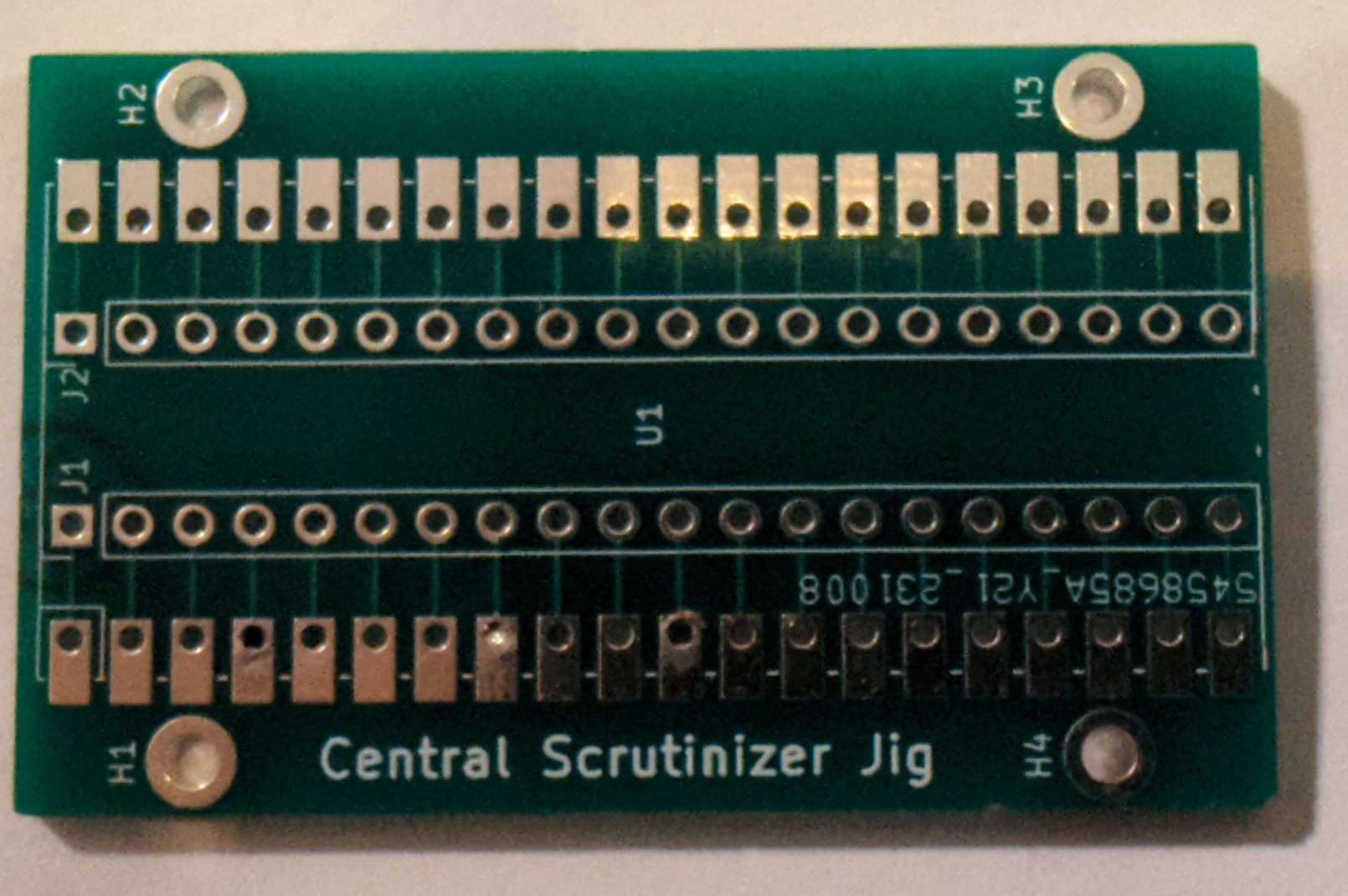
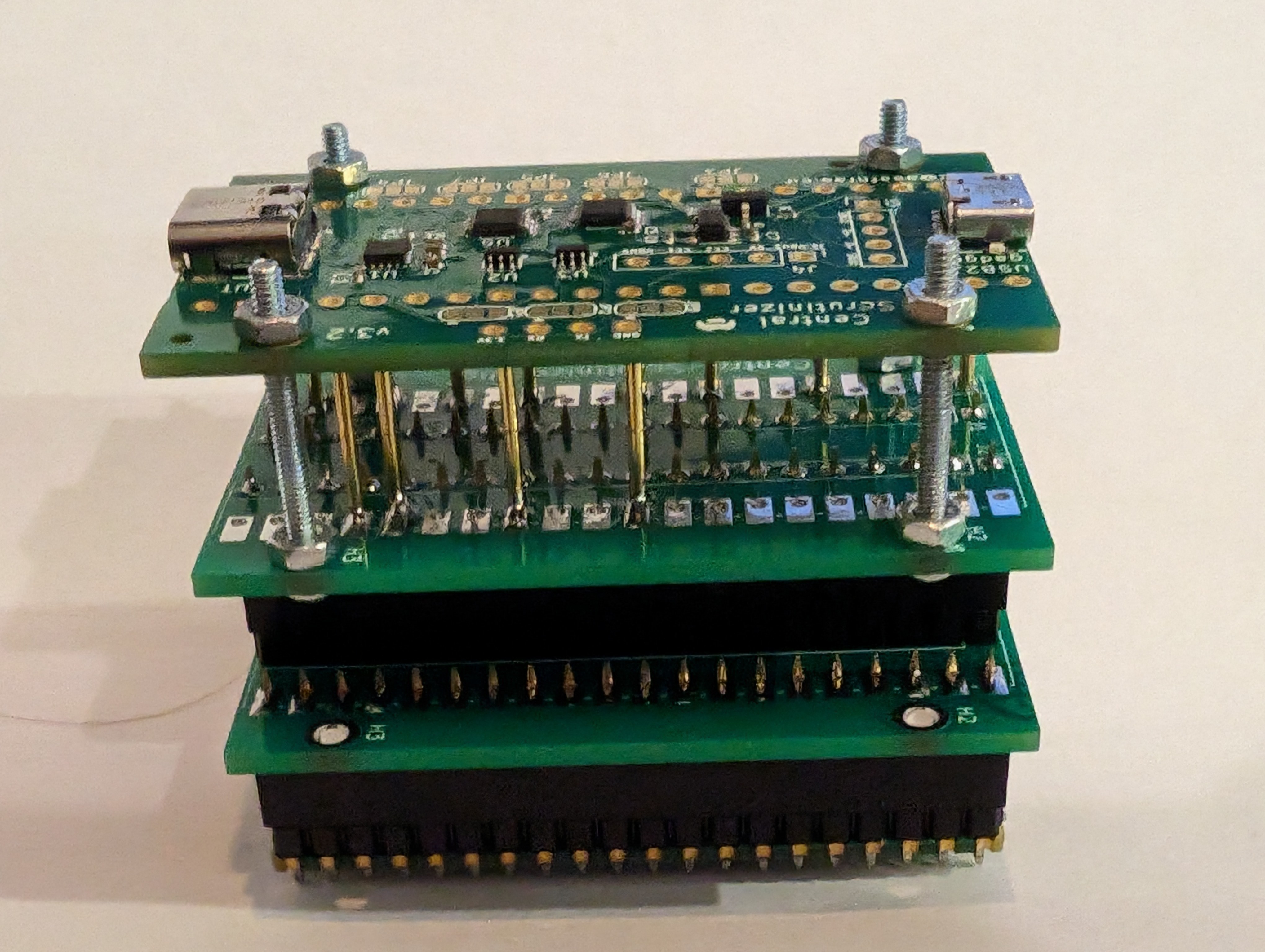
So I settled on a PCB design that would give me some flexibility: a jig PCB can either hold a board or a Pico, but not both. If you want to connect it to anything else, I have an additional connector for that in the middle:
Of course, this results in twice the number of PCBs for the same thing as my original contraption:
The (modest) advantage of this version is that I can swap the top interposer for one that has a different configuration. And this is not restricted to a Central Scrutinizer board either.
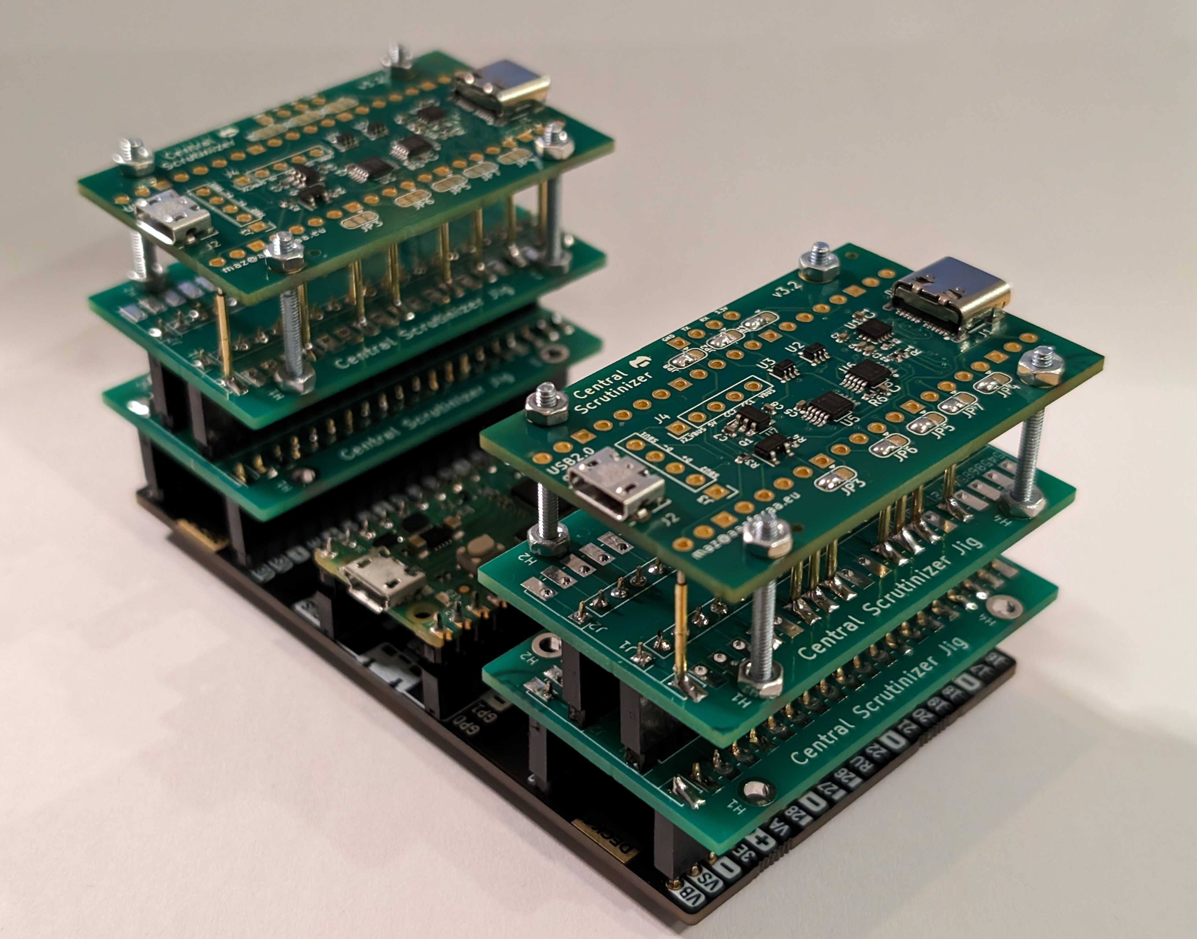
Now, back to my earlier plan of being able to test two boards at once. I found this carrier board (https://thepihut.com/products/pico-omnibus-dual-expander) that allows me to plug two boards. With two test jigs plugged in, and two CS boards to boot, that's quite a setup! I have since replaced the metal screws and bolts with nylon equivalents, which is much safer.
Of course, the PCB design is pushed out in the repo. Feel free to reuse it for something else!
-
Serial to serial
10/17/2023 at 09:54 • 0 commentsThese days, a serial adapter is widely understood as a way to convert a TTL serial stream to a more "modern" (read: more pointlessly complicated) protocol. And that's what the Central Scrutinizer does in its most basic incarnation by converting the serial stream to USB CDC.
However, the good old RS232 is still alive and kicking, specially outside of the embedded environments My test farm, for example, is largely composed of machines that have RS232 interfaces which I connect to my (home made) console server.
There is also a trust issue: It is easier to integrate a pure serial device conforming to the RS323 spec than a USB device running untrusted firmware and potentially capable of tripping interesting bugs on the host side. BadUSB anyone? Of course, *I* trust my code. Who else does? Rhetorical question!
For all these reasons, it is sometimes desirable to trade the convenience of a USB serial port for the robustness and trust of a RS232 connection.
Exposing a Mac serial port over RS232 shouldn't be a big deal: a couple of level shifters, and that'd be it. However, if you want the current behaviour of multiplexing control (such as the reset capability) and data planes over the same channel, you need some on-board processing. Which is fine, as the Pico has two UARTs, and we can use the second one for the upstream connection.
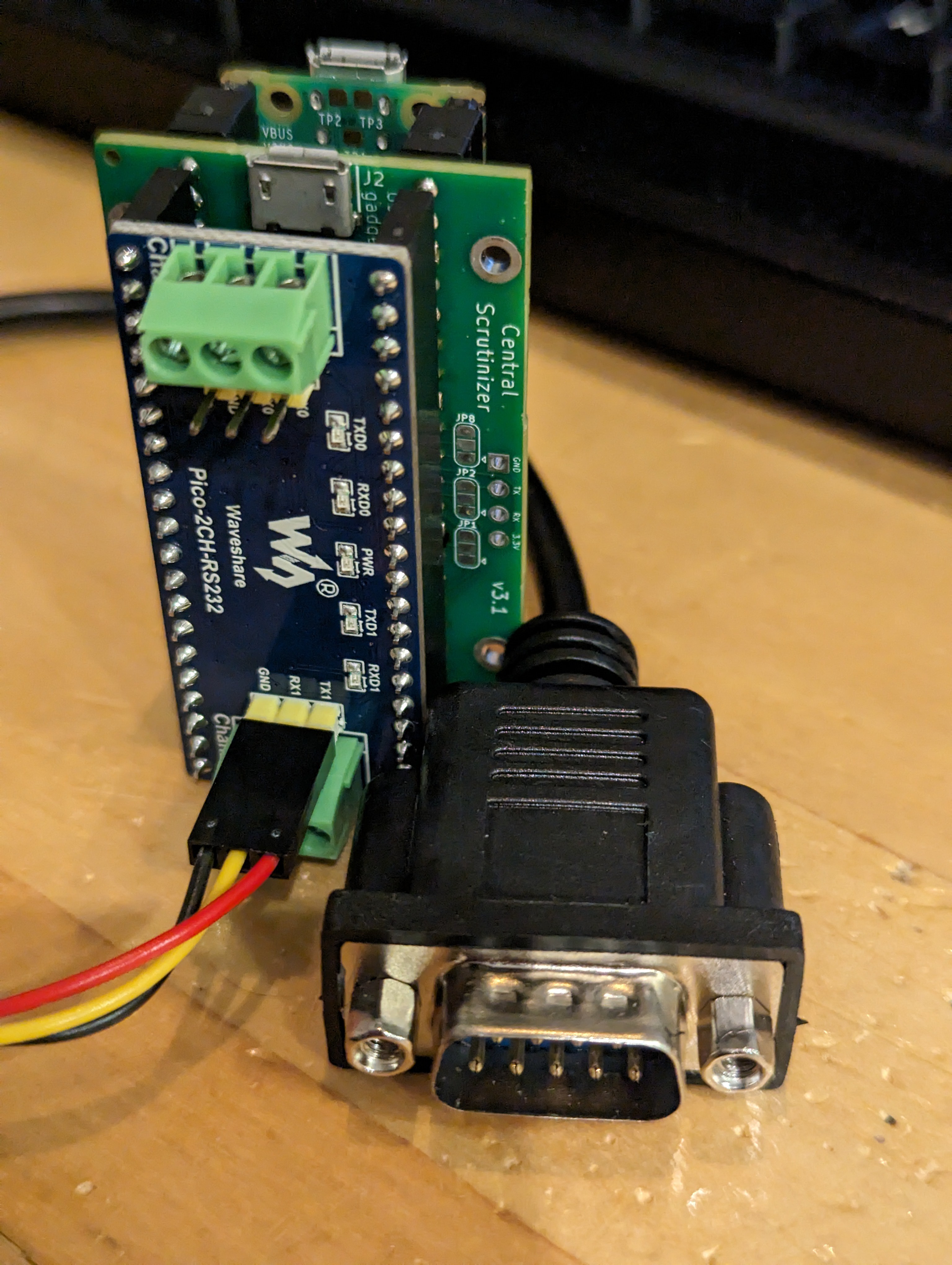
I was looking at fitting a MAX3232 on the Central Scrutinizer when I discovered this add-on board that seems designed for it: https://www.waveshare.com/wiki/Pico-2CH-RS232 A MAX3232, all the required passives, and a bunch of visually annoying LEDs. What's not to like? And it is available almost everywhere (eBay, Pi Hut...).
A couple of software hacks later (all pushed out onto the git repo), we have a full serial to serial bridge. Look Ma, no USB! Well, you still need to apply some 5v somewhere, so you actually need a USB connection. But it can be to a dumb (and trusted) power supply, without any data involved. Oh, and the SW automatically guesses that the RS232 board is connected, so the same build works in all conditions.
A slightly different hack would be to use both RS232 channels and split the control plane from the data stream. Not sure if there is an interest for that though.
In any case, it is pretty amusing to see a modern Mac being accessible over an RS232 connection!
-
Building the Central Scrutinizer, one mistake at a time
10/08/2023 at 11:43 • 0 commentsWhat is this?
I've been building this serial adapter for M1/M2 Macs for some time now, and I thought that I'd document how it all came to life. There is nothing amazing in it. Only that it demonstrates the power of open source software and hardware. I didn't invent anything. I just put two and two together, and end-up with something that people found useful. It doesn't get better than that.
February 2021
M1 mini has landed. Screw macOS, I have other plans.
The Asahi project already has some basics in place (the m1n1 firmware), and thankfully describes a rough method to get a serial port out of the machine: https://github.com/AsahiLinux/vdmtool . That's where everything starts.
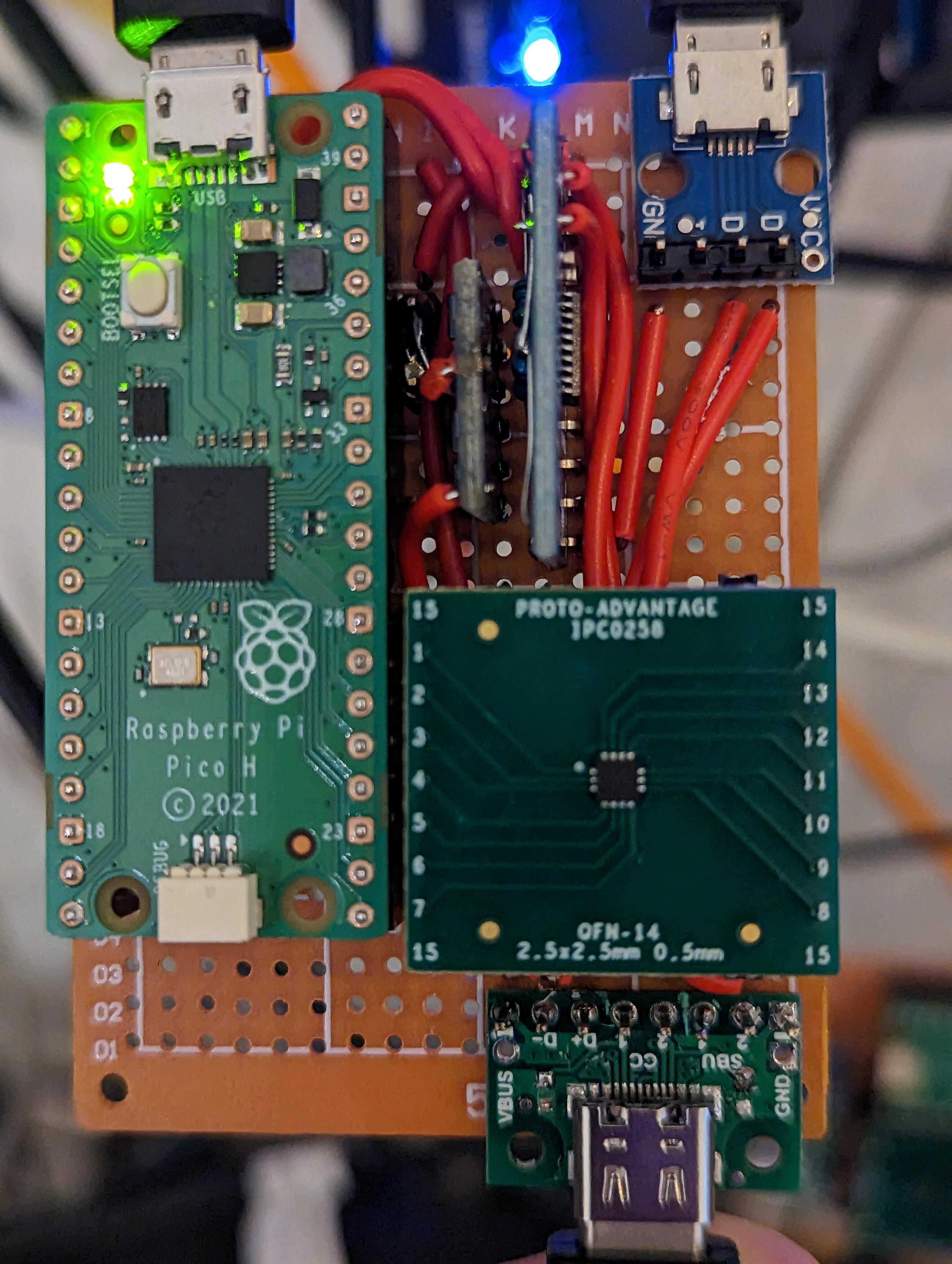
I'm rather adverse to soldering, so aiming for a Lego-like setup by using a bunch of things sourced from Tindie/Amazon/Whatever as well as making liberal use of my junk box:
- a FUSB302 breakout board (https://www.tindie.com/products/reclaimerlabs/usb-c-power-delivery-phy-breakout-board/)
- a USB-C breakout/pass-through board (http://www.elabguy.com/USB3_1_PT.php) exposing the full collection of USB-C signals
- a 1.2v-capable FTDI adapter (https://www.tindie.com/products/saimon/debug-board-usb-to-uart-with-voltage-translator/)
- an Arduino Nano clone
- a piece of Veroboard with a hack together 3.3v to 1.2v voltage divider
- A funky USB-C cable extender (https://www.amazon.co.uk/gp/product/B08BBXMPWZ -- something that shouldn't exist the first place...)
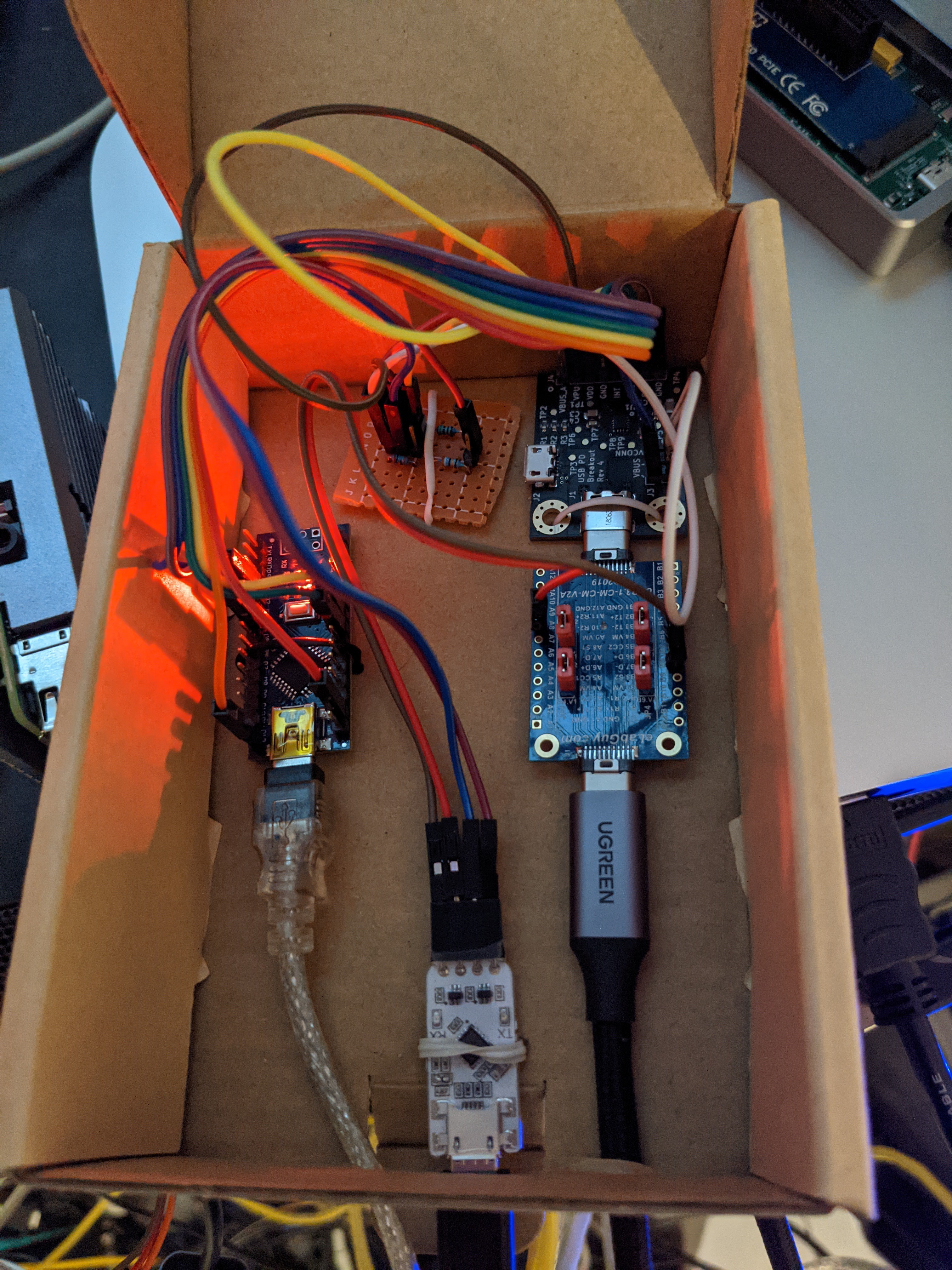
- A cardboard box to house the whole thing
A couple of hours of "work" assembling everything, tons of flying leads all over the place (and probably the reliability of a Morris Minor), and I end-up with this:
Of course, nothing works, and while the Arduino seems to correctly talk to the FUSB302, that sucker keeps connecting/disconnecting. After some debugging (and Marcan's help), I realise that both CC lines are connected all the way, which isn't quite what USB-C expects... RTFM!Multiple solutions:
- hack the FUSB302 board
- hack the cable
- hack the pass-through board
It turns out that the pass-through board has a number of vias to route all the signals across. Which is great news, as I have a very small screwdriver that I can apply to one of these vias (yes, this is terrible -- I don't care):
... and that's one CC line gone for good. Hopefully I won't regret this. And guess what, it all starts working. We have lift off! Both serial and reboot are working, and I can hack on the M1 remotely, without having to hear the stupid "Dong" each time the machine reboots (about 20 times an hour). I narrowly avoided taking the same screwdriver to the speaker...
Now that's what I call engineering! Note the unused micro-USB connector on the FUSB302 board. Eventually, I used that connection to upload payloads to the Mac. To this day, this machine still boots entirely from USB.And frankly, this should have been it. End of the story.
November 2022
Almost two years later. The M1 is still going strong. I wrote a PCIe driver for it, KVM/arm64 is up and running (although I had to work around some of ugly deviations from the architecture as well as some silly HW bugs), and it is my main KVM development machine.
Only problem is that I now have a *second* M1. And I need another serial contraption. Yes, first world problem. Frantically trying to buy the ReclaimerLabs board again, but it is sold out, and the seller doesn't reply to my anxious messages. At no point it occurs to me that I could just upload the design to a PCB shop website and get it done. No.
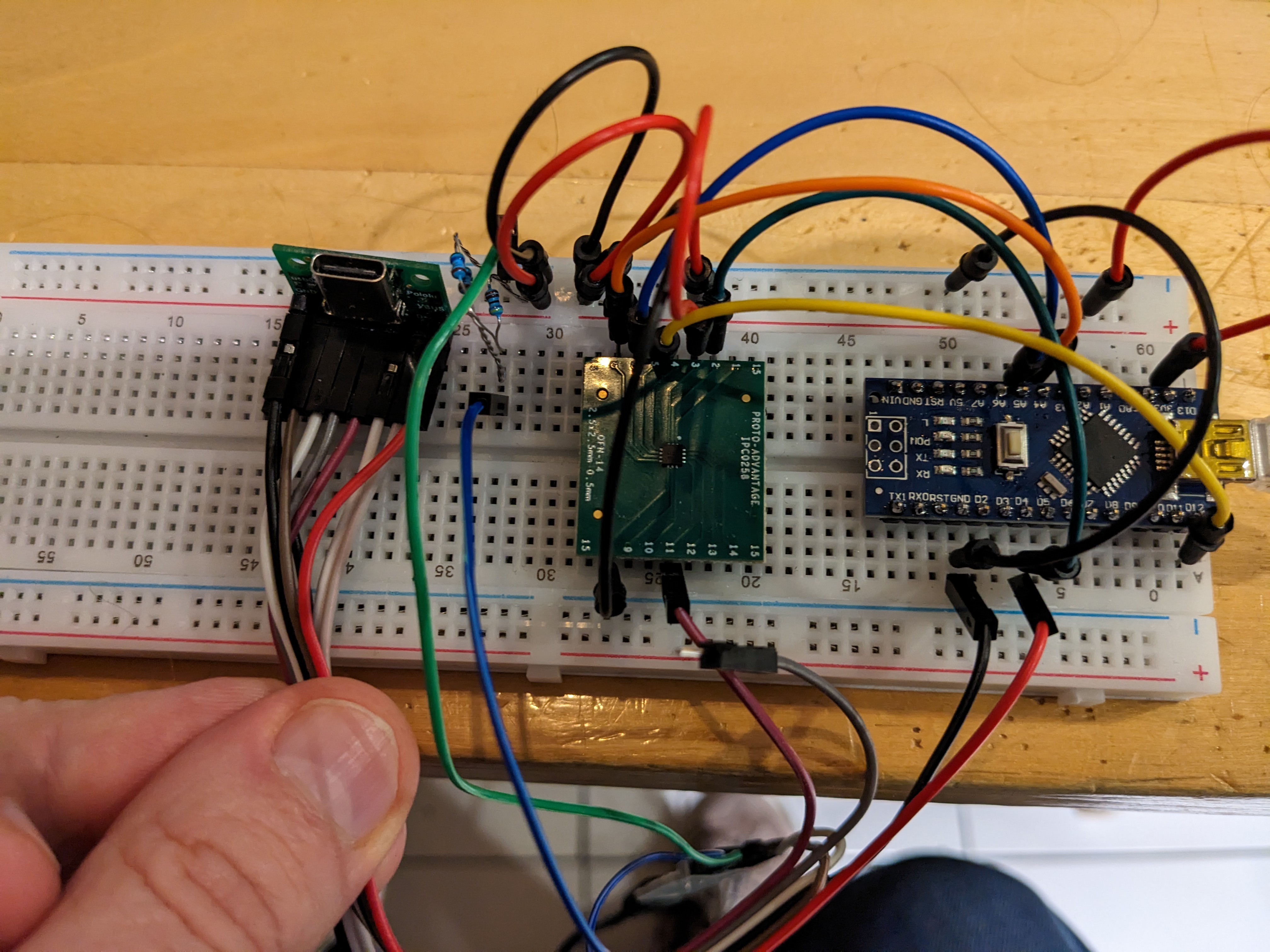
Instead, I decide to reinvent the wheel. Just because I can. And my square wheel looks like this:
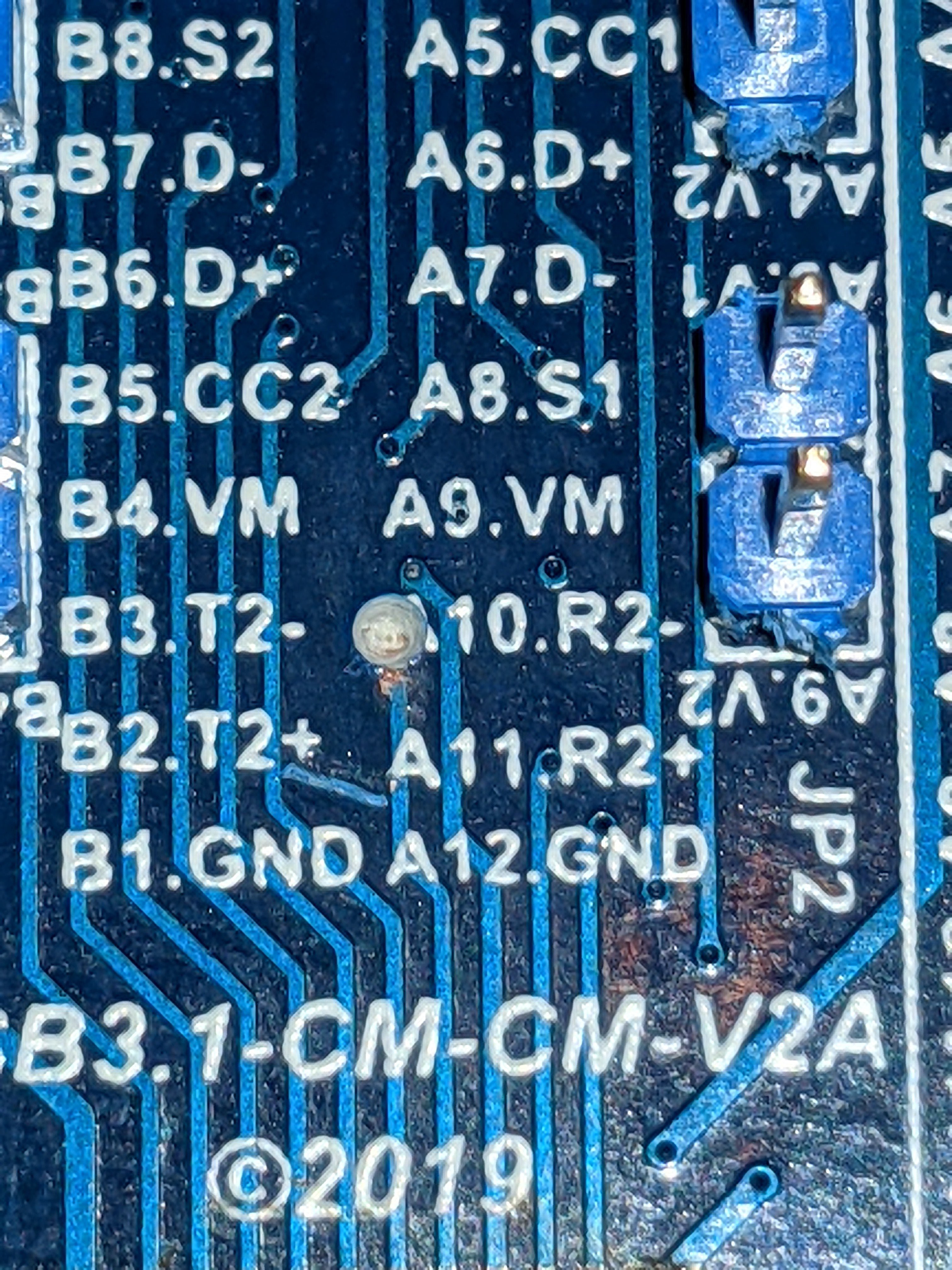
The big square in the middle is a bare FUSB302 soldered on a DIP adapter, the USB-C breakout board is a much cheaper version that exposes the SBU signals (just chop these pesky resistors off the CC lines), and dangling is the same FTDI adapter. And it works! Well, as long as you don't try to move the ball of wires around. Or breathe next to it.
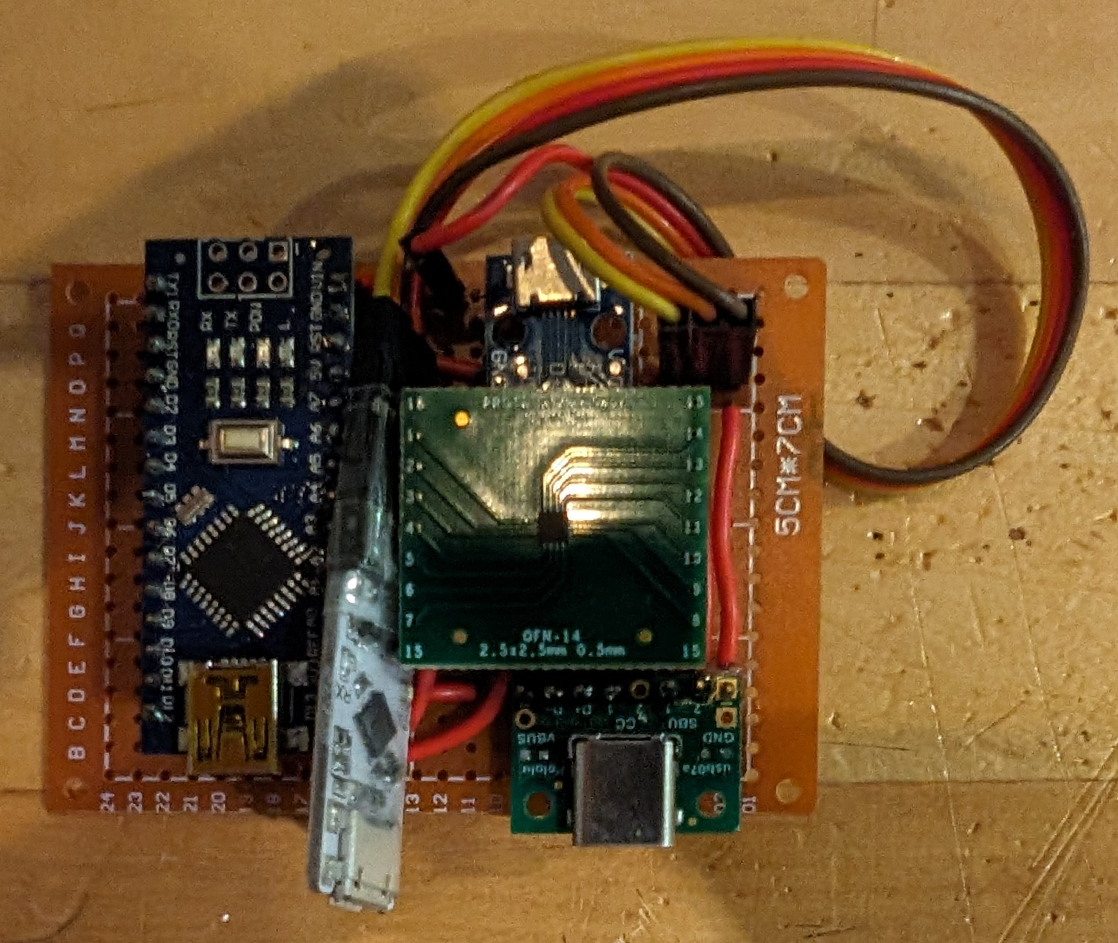
OK, I can't really leave it like this. Surely I can come up with something better integrated. Which involves overcoming my hatred for soldering. Hey ho, let's see what we can do with a veroboard and some wires.
What an upgrade from the first build! My job here is done! Except that once you've done something twice, you start seeing the warts and getting annoyed with them. I definitely do. So what's wrong with this?
- It takes no less than three USB cables to expose all the interesting stuff to a host:
- The Arduino serial for the reboot control
- The FTDI for the mac serial console
- The mac's USB2.0 lines as the m1n1 high-bandwidth link
- My Arduino clones use CH340 UARTs which all have the same USB serial number
- It is quickly becoming a mess trying to find which M1 I'm rebooting at any given time
- No, I don't want to rely on the hub topology for udev rules
- The Arduino IDE is giving me a headache
- I already have an IDE (emacs, in case you're wondering)
- I'm not overly familiar with the Arduino abstractions, and I can't say I like them to start with
- The IDE (again) lives on an x86 box that I want dead
So what's the next move? Well, the two first points are the most annoying ones. Of course, I could integrate a USB hub. But I really hate the idea of adding hardware. If anything, I want less of it. And it occurs to me that if I could use the Arduino UART to capture the mac's serial traffic and multiplex it with the reboot control, I could save a USB connection. Except that the Arduino doesn't have any sort of native USB (hence the CH340).
OK, time to think of a replacement for the Arduino. What are the requirements:
- cheap and readily available (silicon shortage anyone?)
- easy to hand-solder board, no SMT nonsense
- USB device support
- good software support
- preferably with an ARM CPU, for obvious reasons
After a couple of days of looking around only to find that STM32 boards are nowhere to be found and that the various clones don't necessary have what I need, the penny finally drops. What is being designed next door and available by the bucketload? The infamous RPi Pico. It has more features than I'll ever need for this project, and is cheaper than the damn Arduino clones I've been using. Only drawback is that it uses 3.3v logic, while I have at least one signal that requires 5v. Never mind, that's still tempting.
Another few days, and I'm the proud owner of two Picos. Why two? Dunno. I guess I fully expect to destroy one. Also, I've gained some extra Lego bricks:
- Some basic MOSFET-based level shifters (https://www.sparkfun.com/products/12009)
- A TXS0108 board for the serial lines (https://www.amazon.co.uk/AZDelivery-TXS0108E-Converter-Module-Parent/dp/B07V1FY9W5)
Of course, all of that is totally oversized. I only need one MOSFET, and I only have two lines to shift around, not eight. But if I can get things to work, I'll look at being more frugal. If. Maybe.
But real work gets in the way, and then it's the holiday.
January 2023
Happy new year! I'm still being nagged by this silly feeling, so time to see if I can do something about it. When you spend the whole week hacking the Linux kernel and talking to hardware people, what do you do to relax during the weekend? Of course, you hack some hardware and write some software!
So let's draw some basic schematics on paper, get a feel for a basic board layout, and start soldering! I'm still using the DIP adapter for the FUSB302, and start cramming all these small boards on my 5x7cm piece of veroboard. And the result looks like this:
And what about the software? It didn't take too long to port the original vdmtools source code by hacking it to death, coupled to some very basic bridging between UART and USB-CDC emulation. The pico-sdk is easy enough to work with, and the stdio over USB feature makes it incredibly easy to bring something up. Also, plenty of helpful documentation and code snippets to look at. Within hours, I had the basics going on, which means that I was debugging deadlocks when dealing with simultaneous USB and UART traffic. Thankfully, that's the kind of stuff I can deal with.
And I really get what I wanted from it:
- I can multiplex both the reboot control and the serial port over a single USB CDC serial connection from the host
- One fewer cable on my already overcrowded USB hub
- The Pico has a unique identifier in its flash that is used as the serial number for the USB descriptors
- My reboot script no longer reboots the wrong box!
- Upgrading the firmware is super easy, making the hack/test/repeat cycle very quick
OK, project done. I now have everything I want. Except that...
- I still need to build another board to replace the other Arduino-based hack
- I'd like to give something back to the community that allowed me to build this stuff
You now see where this is going...
February 2023
For the past few weeks, I've used my trips to London to play with KiCad. The trains are usually delayed, and the network coverage is laughable. So reviewing kernel patches doesn't really work, and I need a distraction from listening to the depressing news.
So what have I done with it? I've converted my paper sketch into a "proper" schematic, traded the TXS0108 for a pair of 74AVCH1T45, a single BSS108 for VBUS switching, but otherwise it's all very similar. And then I've started putting together a PCB layout. Last time I designed a PCB, it was a 4MB memory extension for my Atari ST, some 35 years ago. Needless to say, things have changed!
One major design decision is that I didn't want to deal with the layout complexity of the RP2040. Yes, I'm a fsckin' chicken. But in keeping with my Lego approach, I aimed for a (tasty) board sandwich and used the Pico as is. Everything else being low speed, low complexity, I could get away with a two layer board and a number of routing horrors. And routing tracks while on the shitty Cambridge/Kings Cross train ended up being incredibly therapeutic!
Also, given that a board only requires one I2C bus, a UART and a couple of GPIOs, it is clear that a Pico could deal with two of them. The layout thus accommodates that by providing two distinct configurations, controlled by a set of 0 Ohm resistors.
Anyway, after much pondering and hesitation, I decided to put my money where my mouth is, and ordered 5 assembled boards from JLCPCB. That process was greatly helped by the JLCPCB Fabrication Toolkit plugin (https://github.com/bennymeg/JLC-Plugin-for-KiCad), allowing me to place the LCSC references directly into the schematic and (mostly) automate the whole thing.
But the best part of it is that the board now has a name. It started as "m1-ubmc", which was both inaccurate and utterly boring. That morning, I was listening to Joe's Garage, by Frank Zappa. And "The Central Scrutinizer" struck me as the obvious name for the board. Central Scrutinizer thou shall be.
Fast forward by a week, DHL delivers a blue box with my five assembled boards, which I call v0. They look super cool. And they are DOA.
I spot the first problem by connecting the board to a 3.3v power supply and measuring the supply on the serial level shifters. It comes out as 2.8v instead of 1.2v. Errr. Good thing I didn't connect the mac to it! One of the resistors on the voltage divider that creates the 1.2v reference is measured at 100R instead of 470R. Check the schematics: all good. Check the LCSC reference: bingo. I somehow copy-pasted the wrong reference in the KiCad design, and the mistake propagated all the way to the assembled board. Lesson learned: check everything at design upload time...
Let's fix this the ugly way. Remove R6, and install a full 1/4W monster instead. With the correct value. Apply power, measure, 1.2v appears, and we're in business. Or so I think.
Let's be brave. I slap a pair of 20 pin female headers on the board, stick my pre-flashed Pico on it and connect it to the host. USB comes up, I2C communication with the FUSB302 is established. A small miracle! The moment of truth: I connect the USB-C cable to the mac, and I get a connection, the serial port gets negotiated, and I claim victory over the hardware!
Except that there is absolutely nothing on the serial lines. No amount of hitting the keyboard leads to any output. I frantically switch back to the non-PCB version, which still works, indicating that I haven't fried anything. Yet. What could be the simplest explanation? I've already checked the power supply to the shifters, and I know the UART on the Pico works. After that it is nothing but wires between the USB-C connector and the shifters... Check the schematics: RX goes to RX, TX goes to TX, and.... And I instantly nominate myself for the title of moron of the month. I blindly followed the labels when drawing the schematics, ignoring the obvious that RX on the mac must be TX on the Pico, and vice-versa.
After a brief moment of despair at the wasted effort, I start evaluating my options. Because I knew I would make mistakes, I've made a point in baking some "get out of jail" options on the board. Specifically, any signal that I would need to extract from a tightly packed connector (such as USB) is exposed on a set of through-hole pads. So the SBU signals are readily available there. All I need to do is to disconnect the level shifters from these lines, and reconnect them swapped. But lifting a pin from a SOT-23-6 package is out of my league. Thankfully (and mostly due to my routing inexperience), I've used vias to connect the SBU lines to the 74AVCH1T45. And I can drill those out without impacting the rest of the design, giving me the option to reconnect the pins to the correct signals using magnet wires.
An hour later, I'm looking at this:
If you think this looks awful, you'll be absolutely right. But it bloody works, and therefore I win.
I now have a fully operational Central Scrutinizer board, and I couldn't be more pleased. On the same day, I amend the design to fix the bugs and order another set of boards. Beer time!
v1 arrives shortly after, and it works out of the box. I push the code and the design out to k.org, and send a couple of boards to fellow hackers for testing.
April 2023
Yes, I'm still working on this crap. No idea why. Actually, I exactly know why. The current design still has a bunch of the original Arduino design limitations:
- A single CC line, meaning it cannot cope with connector swap. Only a single orientation works.
- You must have a fully featured USB-C cable, including the SBU lines. Although the mac can use the D+/D- lines for serial, the board has them hardwired to the micro-USB port for pass-through.
I really shouldn't care, but it ends up bugging me. And when something bugs me, I sleep badly. You don't want to be around me when I haven't slept. Given the choice between pharmaceutical-grade chemistry and hacking, I chose the latter. YMMV.
Solving the first issue itself requires three fixes:
- Connect the CC2 line from the USB-C connector to the FUSB302
- Supply VCONN to the line opposite the closed CC line to power the potential e-marker
- Swap SBU1/SBU2 depending on which CC line is active, as their RX/TX roles also change
Let's start small. I fish out the first Pico prototype (Lego-style) from the junk box and wire CC2 and VCONN. Plug it, witness that nothing works. The FUSB302 can make up its mind what orientation is the correct one, keeps going into reset mode and generally makes no sense. Which is odd, as this is how things should have been wired the first place. This is however reminiscent of the issue I had when I initially started with the first Arduino setup.
One thing is pretty odd in the logs though: with only the CC1 line connected, the measurements that the FUS302 makes to detect the orientation are pretty clear cut: either CC1=2 and CC2=0, or CC1=CC2=0, where 2 means connected to a CC line, and 0 means disconnected. With CC1 and CC2 connected, I get things like CC1=CC2=1, which indicates that both are connected to some sort of e-marker device. This smells of some software bug... What would happen with a stupid USB2.0 cable, without e-marker? Lo and behold, I get a reliable CC1=2, CC2=0 or CC1=0, CC2=2. So something is amiss with the full-fledged cables I use.I start spending some quality time with the FUSB302 spec, and realise that measuring the the current on the CC lines is driven with a set of pull-ups that can be set to CC1 or CC2. Or both. Then I looks at the measurement code. It is absolutely fine, and even documents that we clear the CC PUPs before doing anything.
Actually, it says it, but doesn't do it. Oh well:
        /* Clear pull-up register settings and measure bits */
-       reg &= ~(TCPC_REG_SWITCHES0_MEAS_CC1 | TCPC_REG_SWITCHES0_MEAS_CC2);
+       reg &= ~(TCPC_REG_SWITCHES0_MEAS_CC1 | TCPC_REG_SWITCHES0_MEAS_CC2 |
+                TCPC_REG_SWITCHES0_CC1_PU_EN | TCPC_REG_SWITCHES0_CC2_PU_EN);
VCONN also suffer from the same "sticky PUP" issue:
        if (state[port].vconn_enabled) {
                /* set VCONN switch to be non-CC line */
-               if (polarity)
+               if (polarity) {
                        reg |= TCPC_REG_SWITCHES0_VCONN_CC1;
-               else
+                       reg &= ~TCPC_REG_SWITCHES0_CC1_PU_EN;
+               } else {
                        reg |= TCPC_REG_SWITCHES0_VCONN_CC2;
+                       reg &= ~TCPC_REG_SWITCHES0_CC2_PU_EN;
+               }
        }
Ah, we're getting somewhere. The orientation looks properly detected now. But nothing in the code actually applies VCONN to the opposite pin, and it looks like the relevant code has been killed from the copy of the FUSB302 library I'm using. Which isn't totally surprising, given the above bugs. After some digging, I restore fusb302_tcpm_set_vconn() to its full glory and wire it into the CC probing routine.
I thus declare success, but of course this is pointless, as nothing swaps the SBU signals. What I need is a pair of switches. I could try and hack something on the Lego board, or go straight to an updated board... You know what? I'm done playing with Legos.
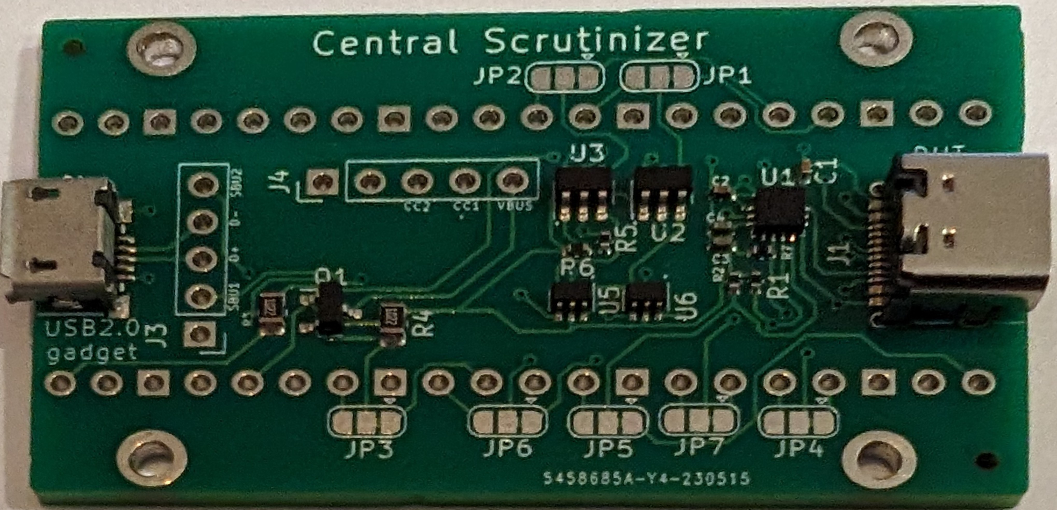
May 2023So here is v2! Not a lot has changed, but U5/U6 are two SPDT switches (NC7SB3157), controlled by a single GPIO, and used to swap SBU1/SBU2 between the level shifters and the USB-C connector.
The other change is that I gave up on the 0R resistors as the configuration selection. Using PCB jumper pads is much easier to work with (just cut the trace and solder the opposite pad). The whole thing works really well, and I can flip the USB-C connector all night long. But of course, I have only solved one of my pet problems. The other problem is still there (USB cables without SBU lines).
At this point I realise that designing this sort of hardware is very different from designing software. Adding incremental features is a huge mistake. Iterative development is a significant cost in time (design) and material (prototype production), not to mention the impact of this stuff going around the planet. What I should have done is to cram all the possible improvements in one single pass, with options to disable or rewire the new bits. Another valuable lesson, I guess. As a result, this version hasn't seen much use (only two people have it, and the rest of the batch is in my junk box).
June 2023Yes, I'm on a roll. Having found out that I could replace my two NC7SB3157 with a single USB switch, I decide to go big by picking something very small, a PI3USB102EZLEX. This little guy can flip *two* high speed analog signals such as USB2.0, and takes absolutely no space on the board. Which means I can use one for my SBU routing, and another to route the USB signals between the USB connector (if using SBU for the serial) and the level shifters (if using the D+/D- lines for serial). Additional bonus, these switches have an "enable" pin that can be used to totally disconnect the inputs. We can use this to fully disconnect the SBU lines when D+/D- are used for serial communication.
These things look tiny even in KiCad, but surely that's not a problem. At all.
And a week later (the usual JLCPCB round-trip latency), I get this:
And it is yet another disaster. Out of 5 boards, only one works correctly. An 80% defect rate. Why, oh why? The fact that one board works correctly means that I'm not solely at fault. So what went wrong? Looking closely at the board, I start seeing some of the problems:
On all the defective boards, I see solder bridges on these tiny switches. On one of the boards, the component is even off-spot by about a millimeter. No wonder nothing works. I guess I went over the limit of what JLCPCB can assemble. It also shows that their QC has "some room for improvement". Understatement of the day! Having moaned at JLCPCB, I get a voucher covering about 30% of the costs, which is better than a kick up the arse.
Anyway, I have a working v3 board with lets me use dumb USB2.0 cables. The software changes for that are positively tiny, and actually result in a cleanup. The other change is that I now expose pads for the secondary Pico serial port. I may use this later...
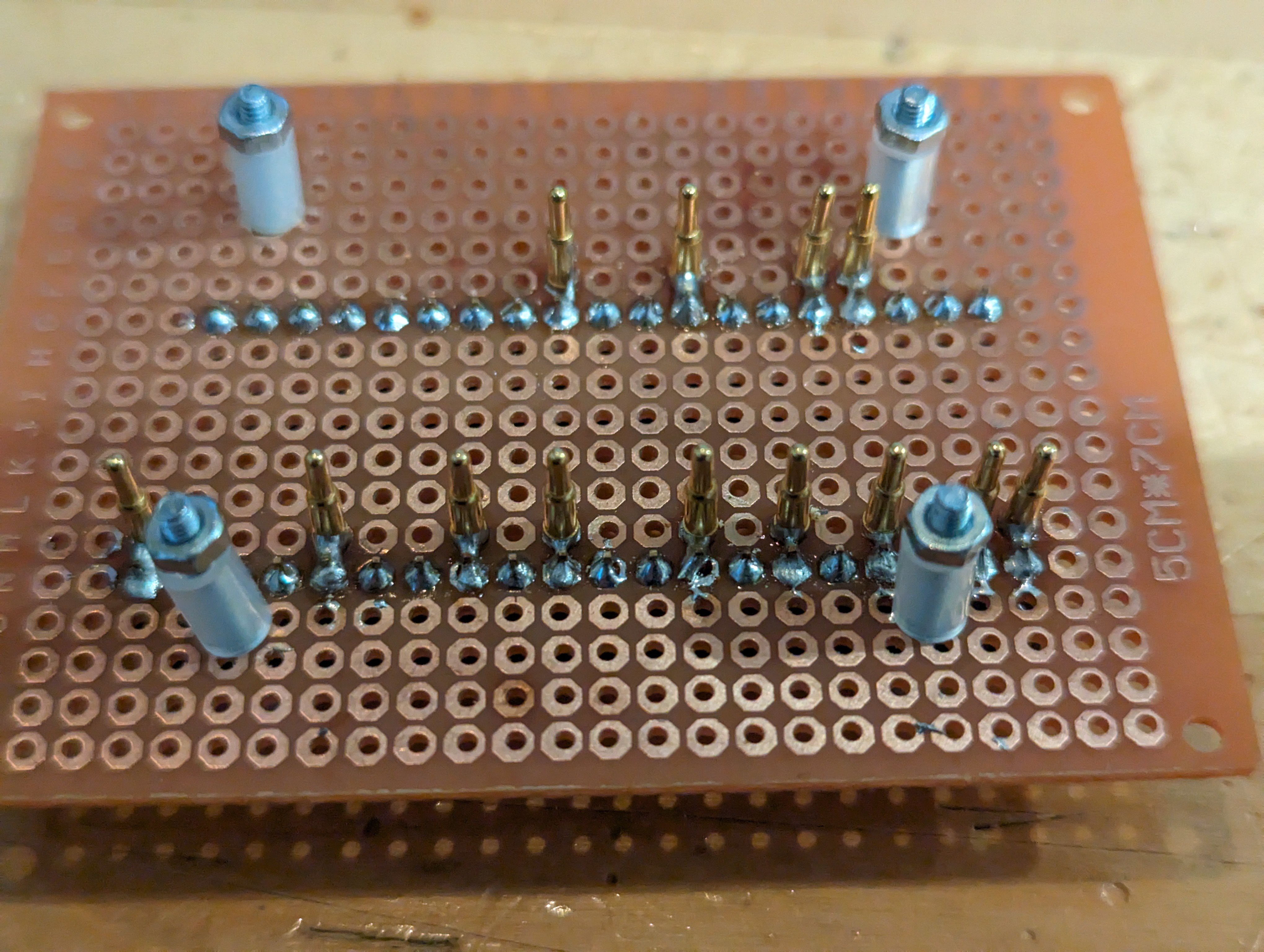
On the positive side, I have improved my testing infrastructure. Having to solder connectors each time I need to test a board was proving both expensive and time consuming. What do people in cases like mine? They build a jig. Unsurprisingly, mine is a quick hack, but it seems to do the trick:
On the other side of this board is the expected Pico. I can simply screw the board to be tested, and the pogo pins are providing temporary contacts. One day, I'll make that a proper PCB, should the need arise.
July 2023
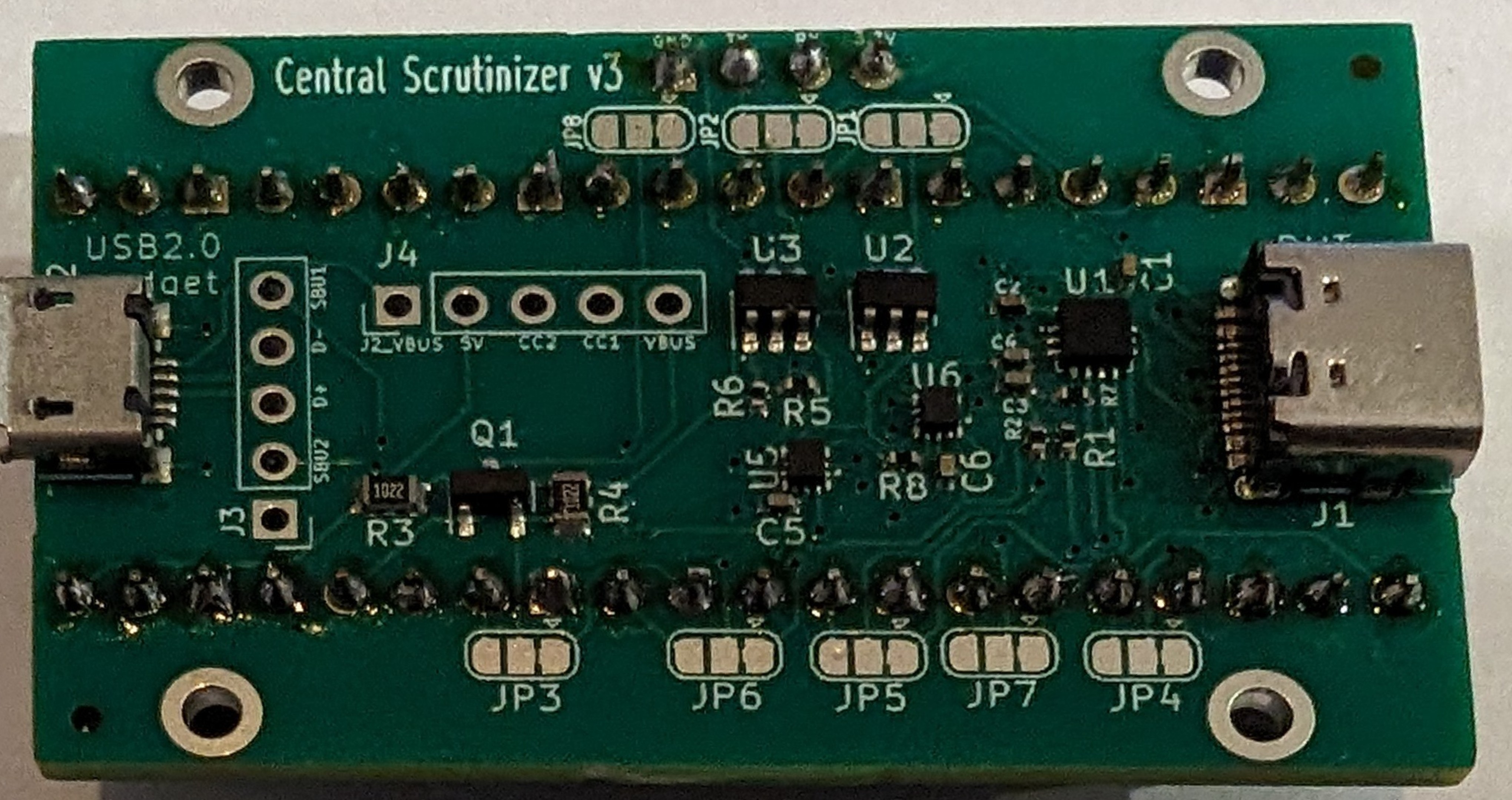
Another month, another version. I have decided to take the v3 lesson on board and reduce my ambitions. Which here means using larger components. I've elected to replace the Diode switches with a pair of RS2227XN. The MSOP-10 package should not cause any issue on the fabrication side, and they are half the price of the previous ones.
Nothing else has changed, and both v3 and v3.1 are functionally the same. Even the firmware behave the same way, which is very reassuring. This is the first version I have started distributing on a "larger" scale. Which is something like 10 boards. Success!
But what is really amazing about this version is that people are starting to build their own! I get reports of runs of 5 to 15 boards being successfully assembled by people who have just checked out the git tree and ordered their own stuff. It makes me really glad I did all of this in the open.
Temporary epilogueThat's it for now. Although I have since built a v3.2 version which is only a very minor improvement on v3.1, I don't plan to make much more changes to it. You have to know where to stop (famous last words...). On the other hand, I have started looking at a more "data-centre friendly" version... Stay tuned!
Central Scrutinizer: a serial adapter for M1/M2/M3
Open source serial adapter / reboot controller for Apple Silicon Macs