Beko Pharm
-
Frame Design
09/17/2023 at 18:47 • 0 commentsIt was time to raid our local hardware store where I got a bunch of pine wood for model building purposes. 13x13x1000mm, 19x29x1000mm to be precise - simply because it looked right to me and was available. I built the whole frame with those two sizes. My
STLwas not exact enough so I had to make stuff up on the go. It was a pretty straight forward process though.![]()
The outer frame is glued but mostly held together by staples. I know what you’re thinking. Heck even my dad told me this would never hold. Hear me out though: First of all I was going to have most of the burden on the inner frame, that is also a lot thicker, and distribute the burden mostly over the covering panels that would be screwed on the top later. Yes, this was flimsy but it held up until everything was screwed together - even for the following photo:
![]()
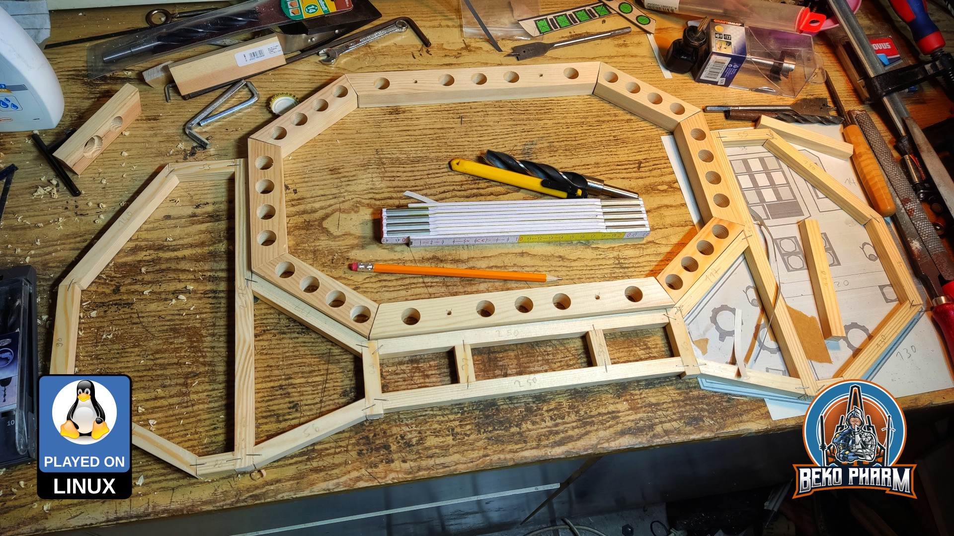
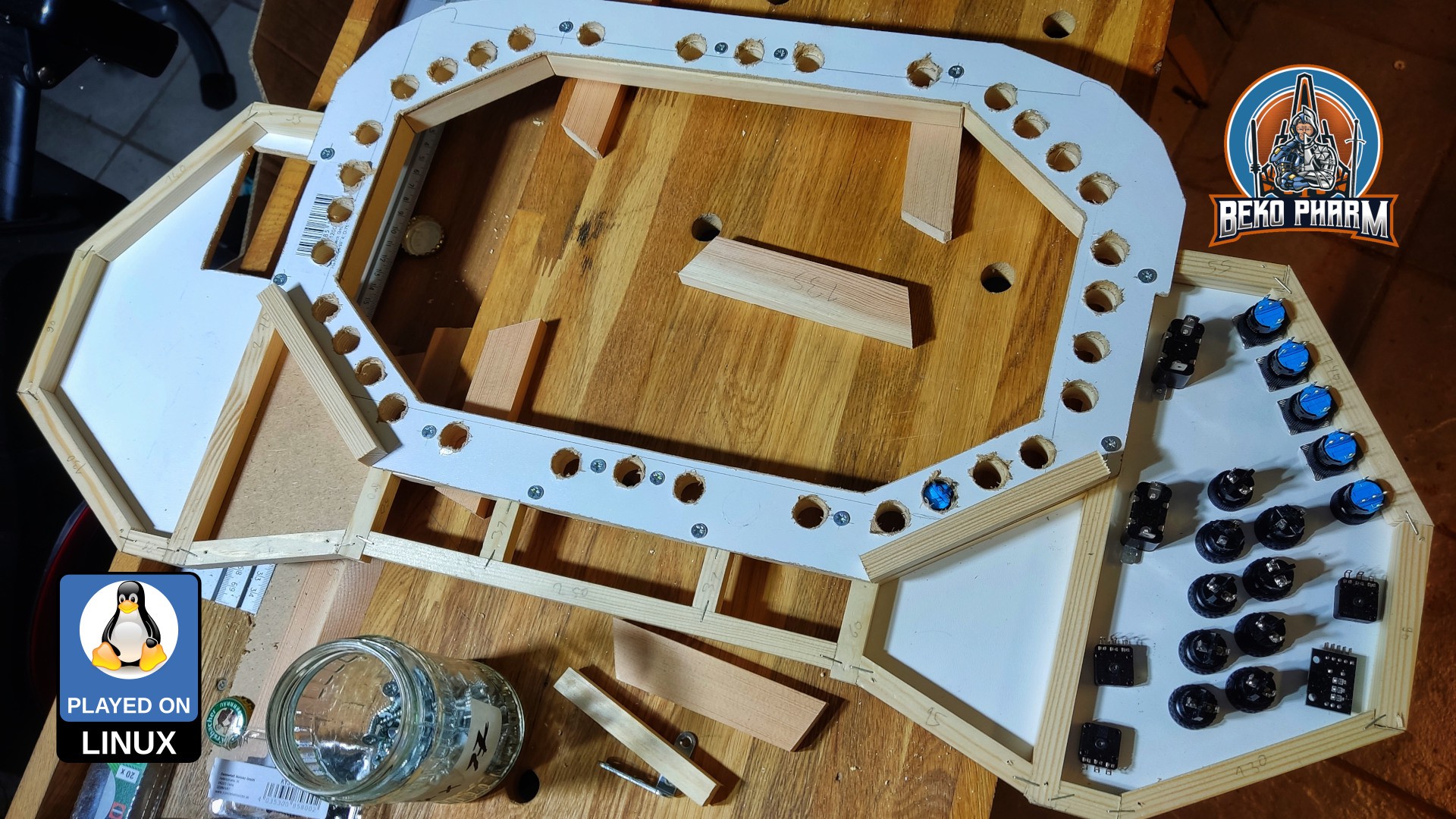
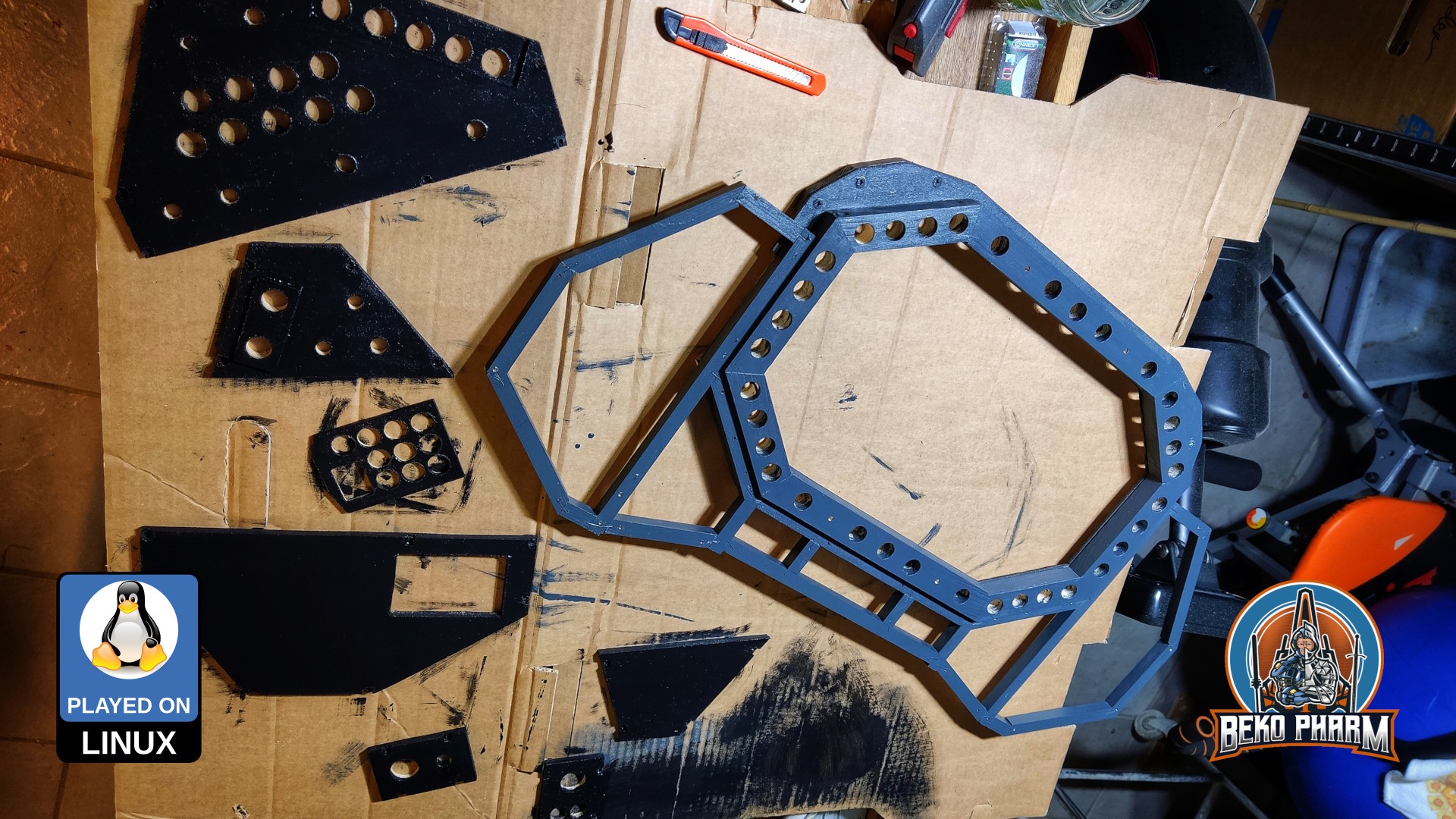
Now things were coming together. The inner panel would hold a shiton of buttons and the
LCDlater. I can tell you that drilling all the precise holes was no fun whatsoever! I also had to get a new drill for this because I had none with the required size.![]()
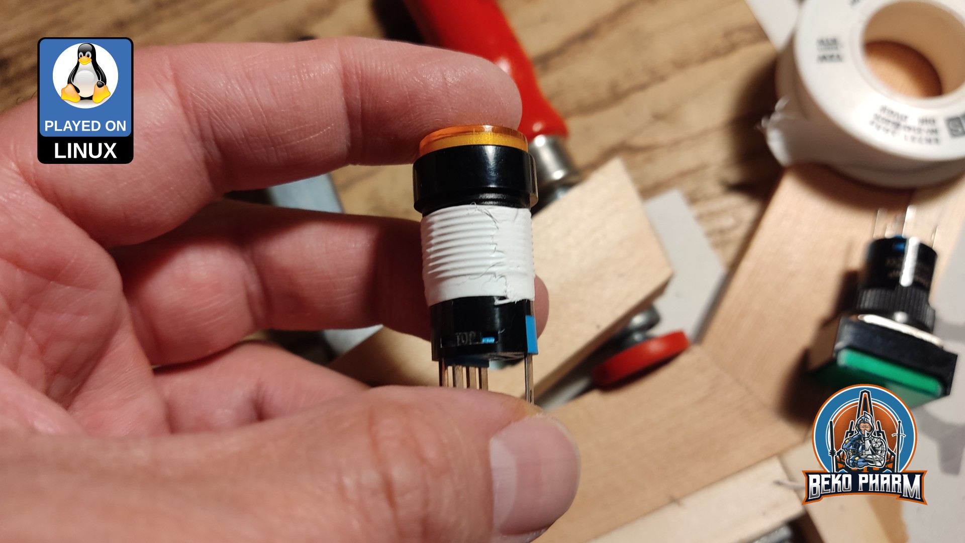
Getting this right was important because most of my buttons would not be able to be fastened with their own screw from the backside. The material is simply to deep for the short length of the screw threads. So every button would have to sit snug in it’s fitting. This worked fine for most holes but some needed encouragement to not wobble around by applying some sealing tape that I usually use for water pipe fittings. It’s not stupid if it works 😛
![]()
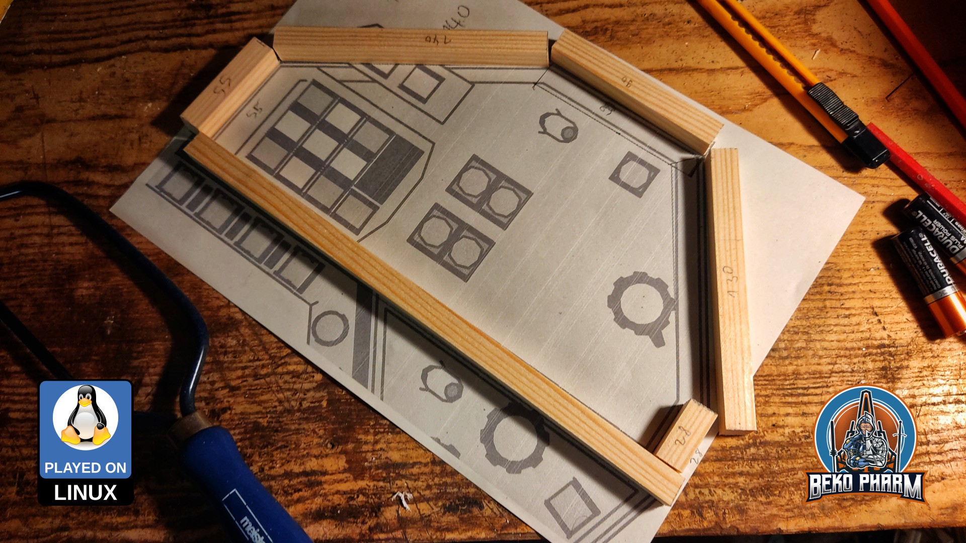
I also can not stress enough how important the cardboard mock-up was. A lot of stuff had to be shifted around slightly for a better fit. The outer frame may be thin but does still introduce an off limits area. In some cases I had to bend the pins of a switch or button to make it possible. Cardboard is very forgiving when it comes to such corrections.
![]()
The panels were realized with two layers of thin compressed wood glued together. I only have a shitty jigsaw so I had to rasp the borders into oblivion in the end. A step drill was also a tremendous help because a lot of the parts - again - to not have enough screw thread to be fastened otherwise. This is especially true for the rotary encoders where I found none with a longer shaft so far and have yet to find a way to make these longer. Sadly the advertised products in my mailbox promising to help with enlargement are of no help here 🤡
I’m going to replace the wooden panels with a backlit variant made of acryl glass eventually. The idea is to replace the panels 1:1 with the exact same construction method of two layers sandwiched together.
![]()
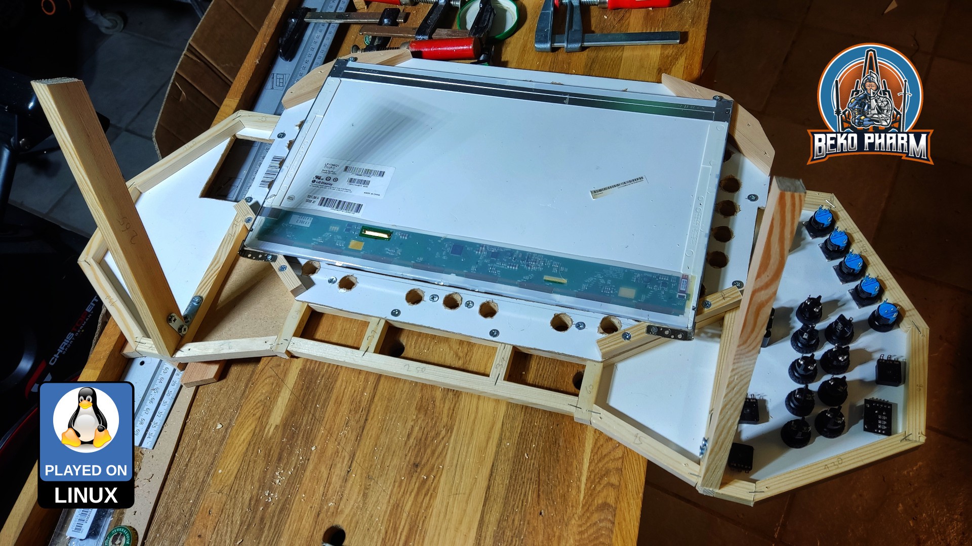
Next was the backplate that would add a lot of stability to both frames. It connects the inner and the outer frame with screws of various length. The lower support area for the
LCDis also already on the picture. I considered adding a little more depth for the wiring of the buttons. Some would be sitting on the LCD corners. I opted to leave it at the depth it is and bend pins again later simply because it would look better this way. I’m also going to add an inner bezel for theLCDframe at a later point.![]()
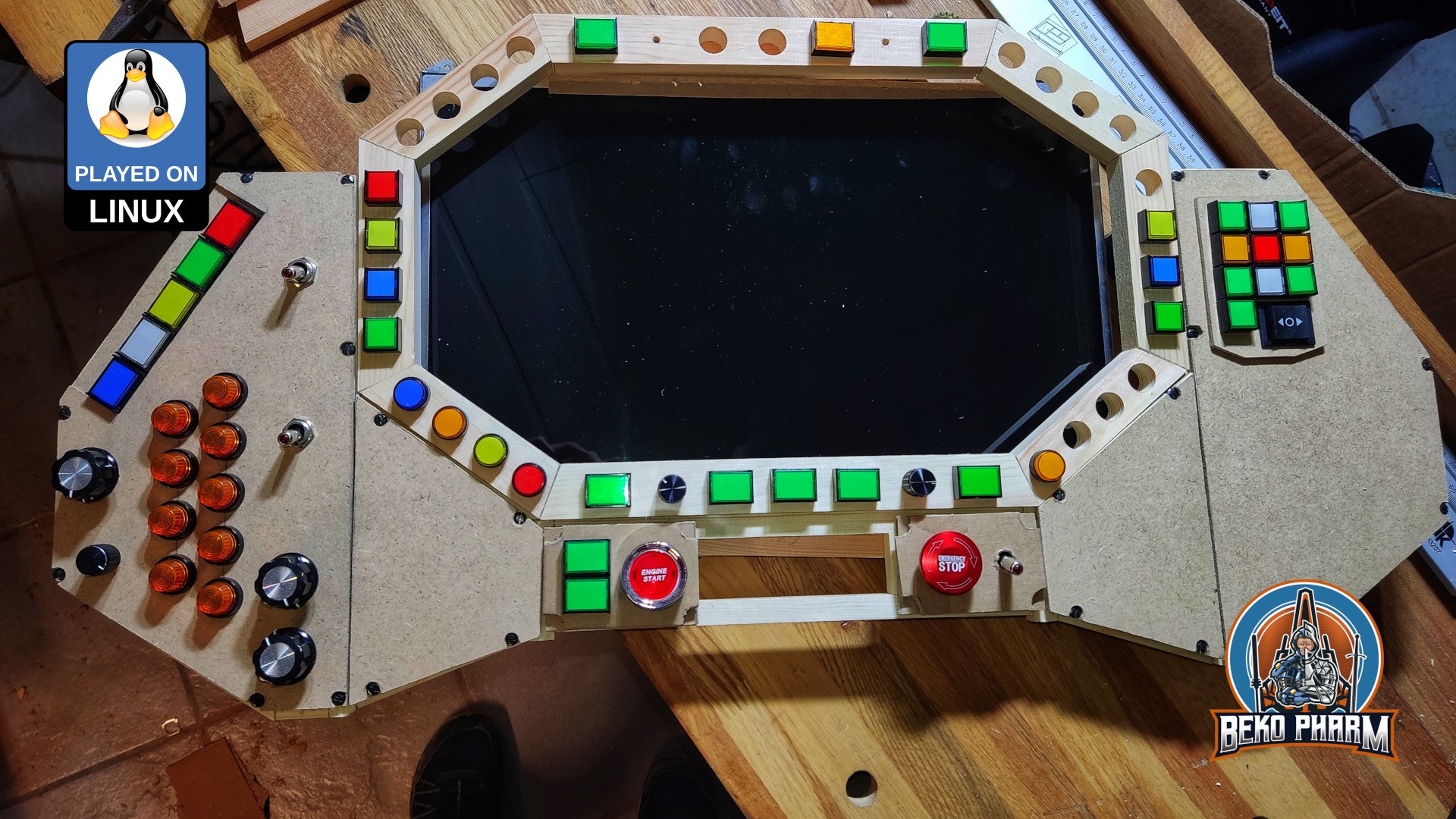
At this point I was in need of a “temporary” stand to work on this more comfortable. This temporary stand was kinda incorporated into the final construction later. I’m going to eventually build a full cockpit around this but for now it’s just sitting on my table. It got additional stabilizer bars later so it wouldn’t wobble on each button press any more. The 17.3"
LCDis really a tight fit here and I’m glad that everything worked out so good. I was totally winging it at this point because mySTLdid not go into too much detail on the backside.![]()
Everything visible was painted in the end. There is not much to say about this. Colours are anthracite-gray and black. The colors don’t really shine, like the picture may imply. The coat of paint was simply not dry yet.
![]()
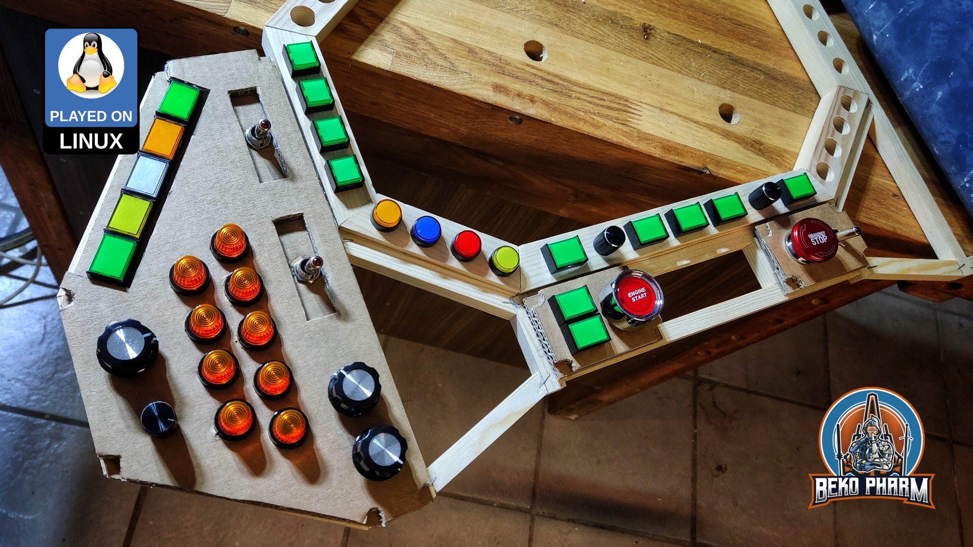
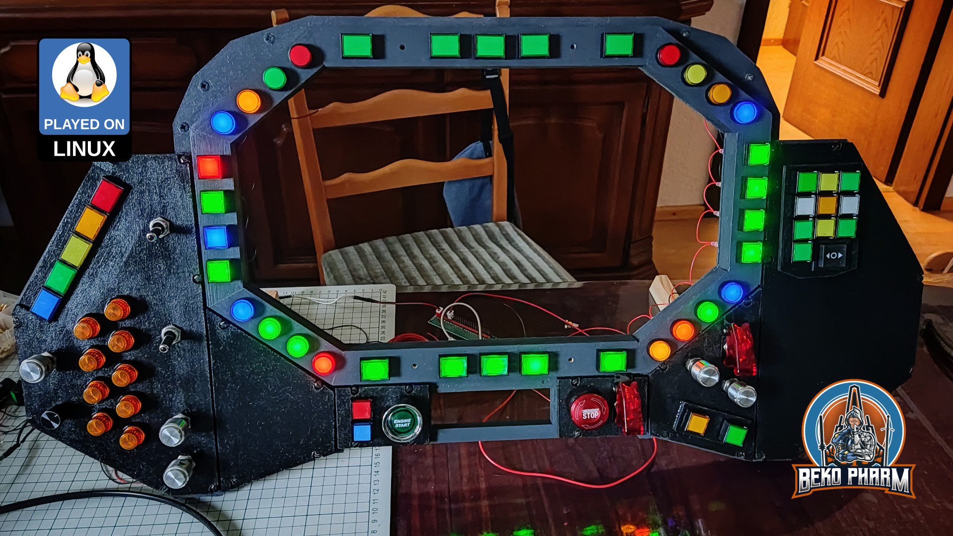
I waited another day for the paint to dry and assembled all parts for the long and dull wiring process. Yes, there are still some empty spaces. For some I’m still waiting for additional buttons to be delivered and for some I’m simply uncertain what to put there. Some gaming sessions should reveal what’s missing. I also didn’t build the lower panel yet because this part would be in the way when put on a table. I’ll probably design a temporary button box on the side for the elements that I was going to put there.
![]()
Originally posted at https://simpit.dev/version-2/frame/
-
Mock-Up
09/17/2023 at 18:42 • 0 commentsThe 3D design was followed by months of doing nothing 😩 until I realized that this would go nowhere without starting. So I found myself sitting down each evening and work on some mock-ups. Even if it was only for one or two hours. At some point would my kids show up and ask questions or hand me tools. Who would have guessed.
![]()
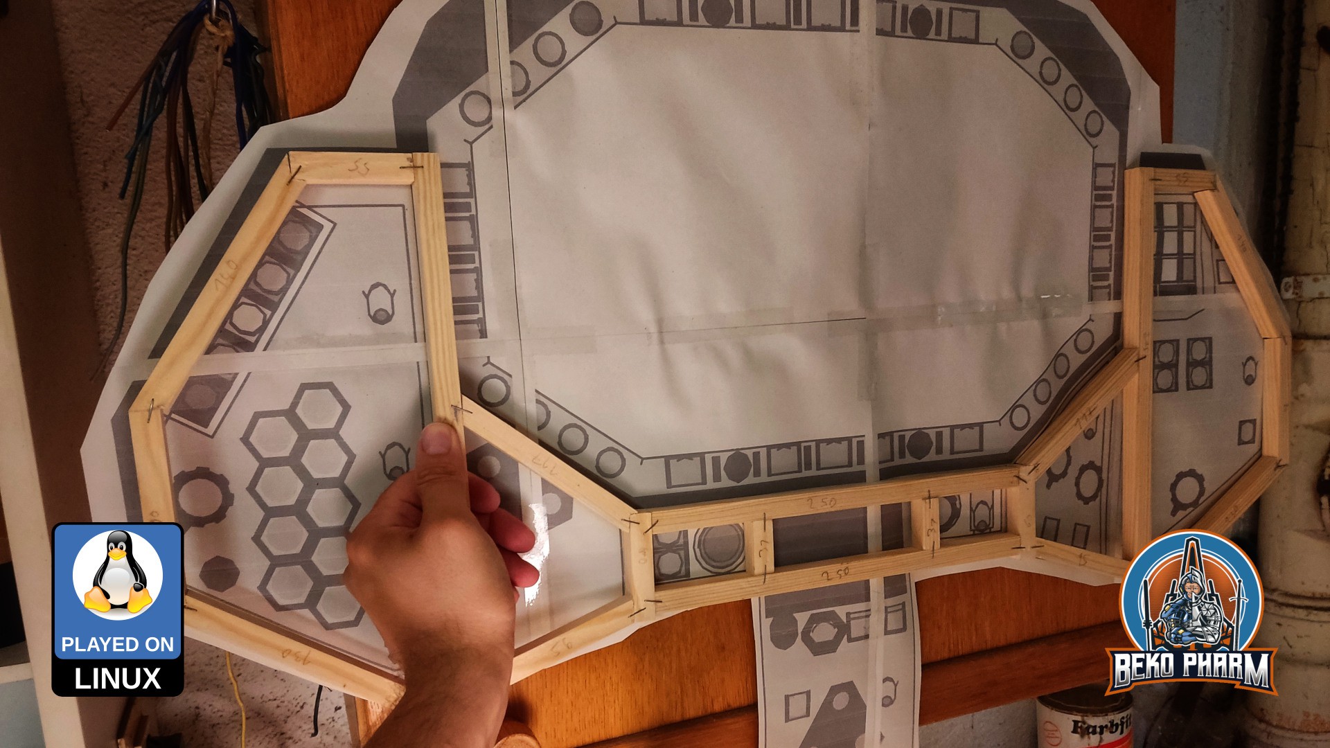
It payed off that I went with mock-ups first. Even with a rough 3D model I run into several small issues that had to be corrected.
For the Mock-Up I had to export my 3D model somehow first. After messing with various online converters, that all failed to produce a usable result from exported
OBJfiles I eventually found out thatWings3Dhas an export toSTLbuilt in. Man did I feel stupid. From there I imported theSTLintoInkscapeand added variousA4papers to the scene to print everything and tape it together. This was the first time that I got an actual idea of the dimensions and wondered what I did get myself into.![]()
Originally posted at https://simpit.dev/version-2/mock-up/
Primary Buffer Panel v2
A glorified DIY joystick controller with an LCD (‘MFD’) and plenty of RGB.