-
Design Ideas
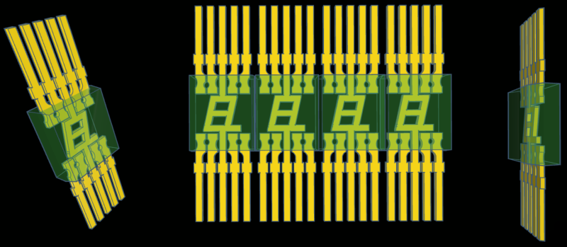
10/01/2023 at 22:50 • 0 commentsThe look of these vintage displays are what drew me to them, and the gold pins are an important part of that visual appeal. I'd like to be able to keep the pins straight and visible, and preferable gold. Unfortunately, solder will cover some of the gold finish, that is unless gold solder is an option (doubtful). I haven't made any decisions yet, but soldering them down to a PCB is the backup plan. My primary plan is to use a socket of some kind.
To help consider ideas, I made a model of the displays in Tinkercad. I'm rather new to 3d modeling, so it was good practice. It's not perfect, but it should work.
![]()
I also mocked up some PCB mounting patterns.
![]()
-
Exp 1 Update
09/29/2023 at 00:30 • 0 commentsWhile I wait for parts to use the 7-segment Soviet displays, I picked up a few HP units that will fit on a breadboard. I already verified the driver chips are functional, so I didn't really need these new displays, but I got them anyway. They seem to work fine and I really like their all-red look. The part number is 5082-7653. I've also worked on a rough draft of the circuit board, once the new parts arrive I'll verify some measurements and get the boards ordered.
![]()
![]()
-
First Experiment
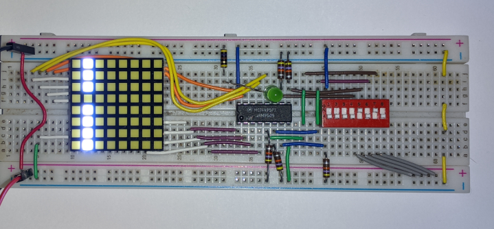
09/26/2023 at 01:08 • 0 commentsI put together a quick breadboard circuit to test the functionality of the MC14495 driver chips I purchased. I don't have a breadboard friendly common-cathode 7-segment display at the moment, so I used one column of a 8x8 matrix and a single LED to test all 9 outputs. I also added a dip switch to test the 5 inputs. Thankfully, all the chips seem to be fully functional.
The lit column is (from top to bottom) a, b, c, d, e, f, g and h+i. The currently displayed character is 'A', so all segments except d are lit. Additionally, h+i is lit because the character is a letter and j is not lit (green LED) because the data inputs are not all 1's.
![]()
-
LED Driver
09/24/2023 at 01:52 • 0 commentsFor a 4 character module I'll need to drive up to 32 LEDs with a common cathode configuration. Each character in the display will be a hexadecimal character of a 4-bit binary number. Additionally, the module must have a have a single latch line to latch data from a bus.
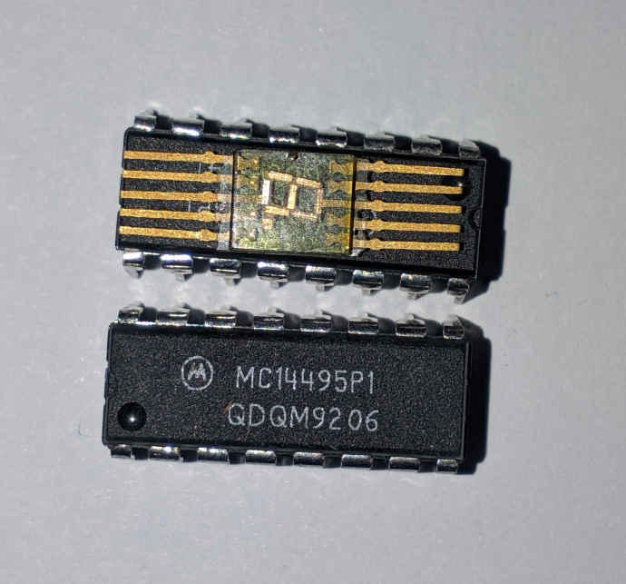
The MC14495 "Hexadecimal-to-Seven Segment Latch/Decoder LED Driver" is a common suggestion. It is designed for common cathode, it has a character ROM for 7-segment hexadecimal characters, it has built-in 290Ω current-limiting resistors and it has a latch. Unfortunately, to keep it simple, it requires 1 chip per character. And, they are not as common and cheap as they used to be.
For I/O, the MC14495 has a 4-bit data input (A, B, C, D) along with a latch enable (LE) input. For outputs, it has one for each segment in a 7-segment display (a, b, c, d, e, f, g), and a line that is low for characters 0 thru 9 and goes high when the character is A thru F (h + i). Finally, it has a line that is normally high-impedance but goes low when the character is F (j). I don't have a use for the (h+i) and (j) outputs, so I'll tie them to ground.
The MC14495 is larger than the L104V, which presents a challenge in keeping the finished project small enough and nice to look at.
![]()
-
The 7-Segment Displays Arrive
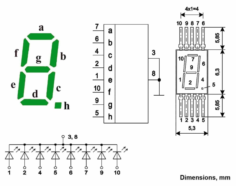
09/23/2023 at 14:59 • 0 commentsFrom the photos and datasheet I knew exactly how big these parts were, but there is something different about holding them in your hand. These things are small, very small. I don't know how I'm going to breadboard the circuit with something so small. I don't want to solder the pins yet so I'm currently coming up with a solution. For now, I'll post photos and specs of the LEDs.
I'll be conservative the first time I light up these LEDs. Both sources of information agree on 3v, which sounds about right for a green LED. But they disagree on maximum current per segment, one says 7mA, the other says 11mA.
Here is the partial datasheet provided by the seller:
![]()
And here are the specifications listed in the description:
![]()
Important part in the AL304V datasheet, auto-translated from Russian:
![]()
 Robert


