Michael Gardi
-
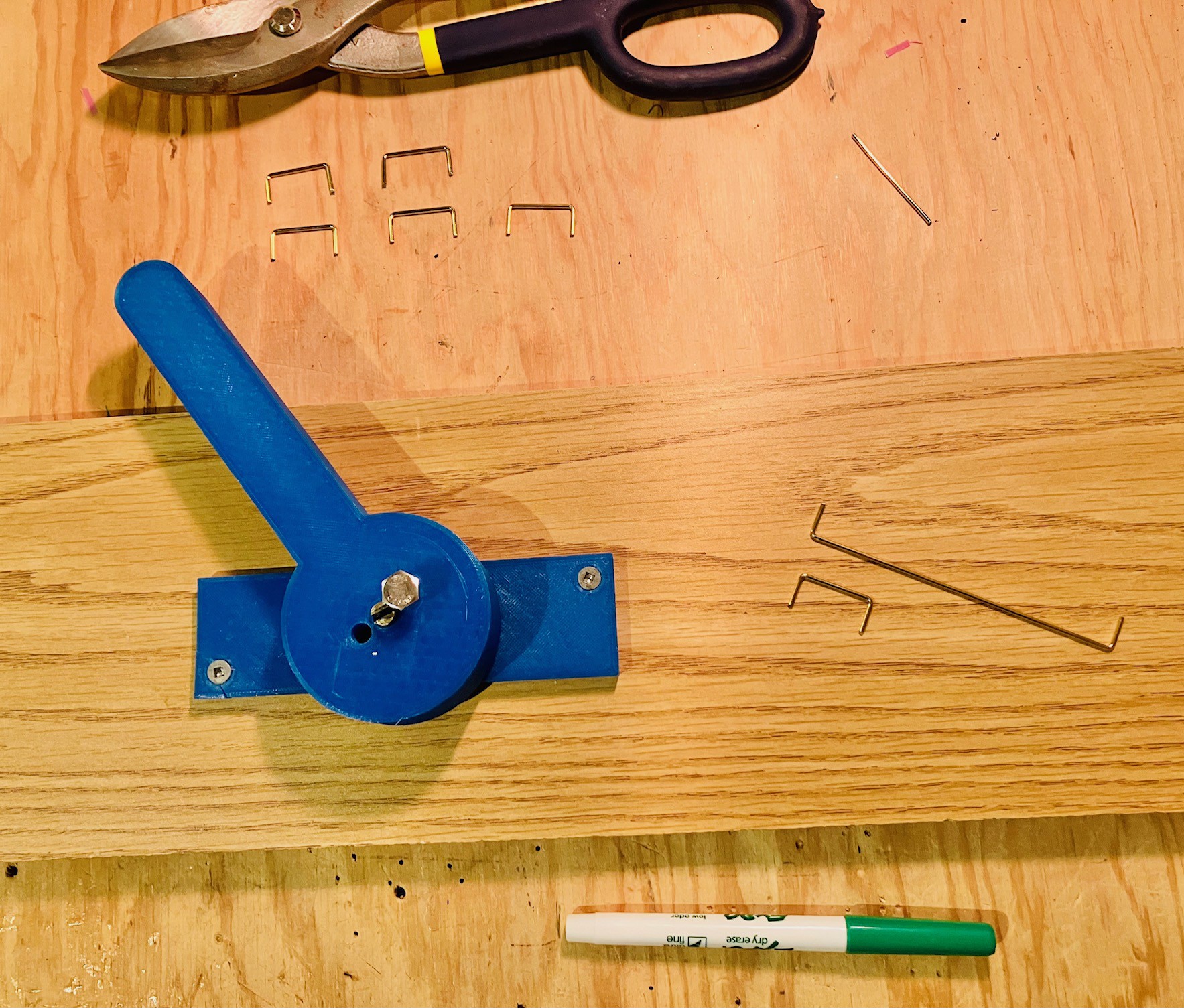
Bending Wires
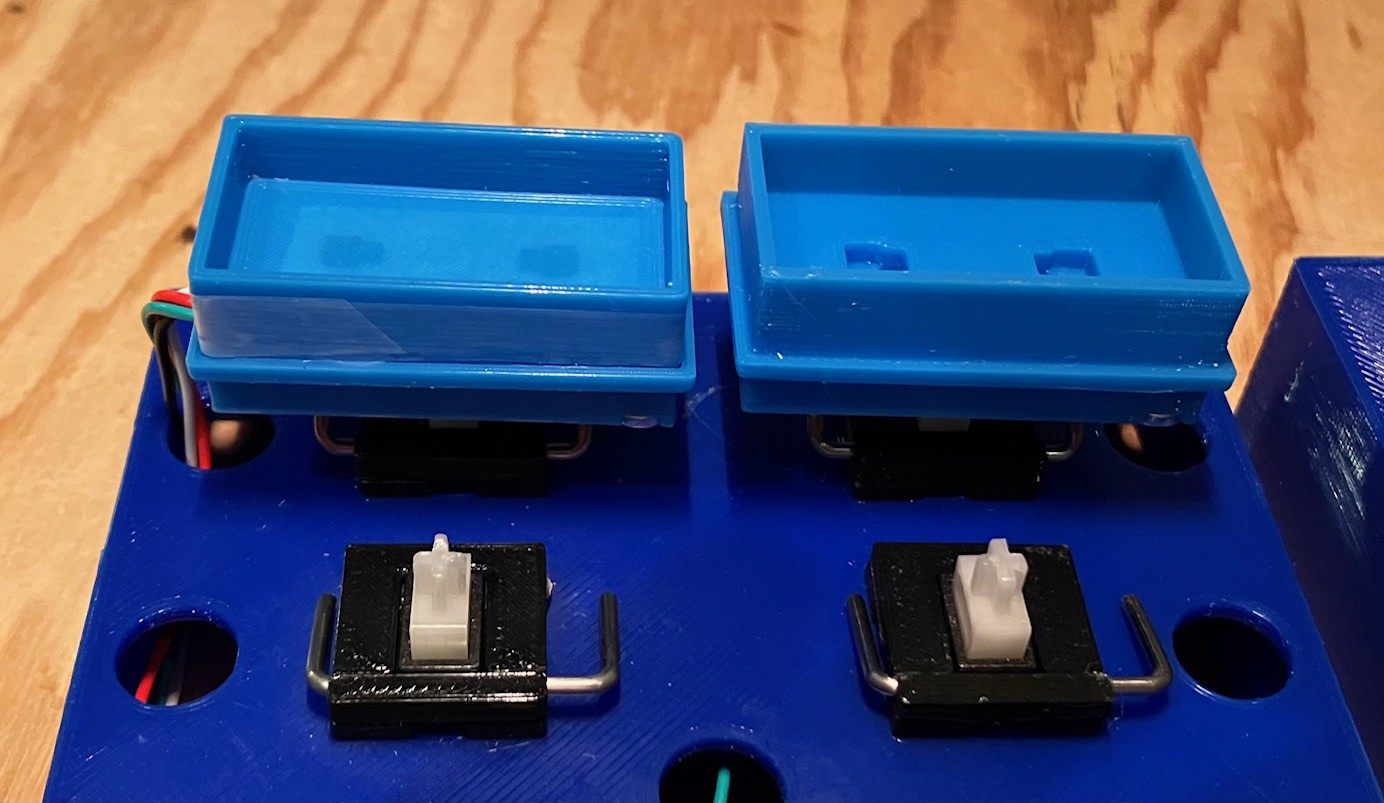
10/30/2023 at 18:37 • 0 commentsThe PCBs and the SMD hall effect sensors have shipped but are still a few days away, so I'm making sure that I have everything else I need for my MacroPad Version 3 build. I still have a good supply of the Futaba MD-4PCS switches, but I only have four 2U stabilizer wires for the Tile Holder Switches. Fortunately I have unused 6.25U and 7U wires that I can use to make some 2Us with.
When I first got my first 3D printer in the Spring of 2018 (a Prusa MK3) it was in part because I wanted to make a Digi-Comp I replica ( I had one back in 1965 when I was 12). In addition to the printed parts, the build required a dozen "logic" and "clock" rods to be fabricated from piano wire. That motivated me to make a wire bending tool based on the following YouTube video:
I have used that tool dozens of times over the years. Well worth the effort to make it. So I dusted it off and using the existing elbow bends on the longer stabilizer wires made bends at the 2U mark and cut away the excess to make 4 additional 2U stabilizer wires.

Above I have make two 2U stabilizer wires with 2 to go.
If you don’t have extra stabilizer wires to salvage, 1.6 mm brass welding rods will do the trick and are cheap and readily available.
I think I now have everything in place to start the build when the parts arrive.
-
Not As Done As I Thought
10/24/2023 at 19:20 • 0 commentsI've reopened this project as ongoing. It never fails that as I'm wrapping up a project I think of what I would have done differently were I doing it again. So in my Final Thoughts for this project so far I said:
Wiring the Tile Holder Buttons was a pain and represents I think the weak point in the build. This is especially true since repeatedly pressing the buttons is going to put stress on the solder joints inside. Perhaps some hot glue would help. If I were doing it again I would probably design some small PCBs to hold surface mounted versions of the hall effect sensors.
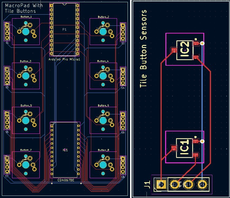
And sure enough I had a button failure after a couple of days. So the small PCBs for the buttons is a go for sure. While I'm at it I decided to do a PCB for the main part as well. I don't know if anyone will ever want to build a MacroPad With Tile Buttons, but the dead bug wiring would probably scare them off if they did. With a PCB it will be a piece of cake.
Obviously not to scale relative to each other but these give you an idea where I'm going with this.
Update 2003-10-25
The PCBs are off to fabrication. I have posted the KiCad 7 files and Gerbers to GitHub.
-
Final Testing
10/20/2023 at 19:24 • 0 commentsI created a Calibrate_MacroPad_2 sketch that took into consideration the small differences between this project and the A Tile Based MacroPad project. These small differences resulted from two wiring changes I made:
- When I started testing I realized that I had switched a couple of the pin assignments between the pro Micro and the multiplexer (the S2 and S3 selector bits). Rather that rewire I just switched the pin assignments in the sketch.
- I wired the sensors differently for this project to make the wiring neater. This required that the mappings between the buttons and the sensors need to change.
I ran the calibration without issues and copied the midValues and calValues tables produced to a new MacroPad_2 sketch. Then I made the same pin and sensor assignment changes that I did to the Calibrate_MacroPad_2 sketch.
And that was it. The new MacroPad 2 was up and running.
I have updated GitHub with the new sketches and the additional models required to make a MacroPad 2.
-
Wiring (Part 2)
10/18/2023 at 22:09 • 0 commentsI have finished installing all eight Tile Holder Buttons which means that the wiring is done.
I made sure that there was a good deal of slack in the wires coming from the buttons to ensure that the buttons were free to move when pressed.
I attached the top with four M3 x 6mm bolts to make sure that the buttons are secured while I start the testing.
-
Progress
10/17/2023 at 22:11 • 0 commentsThe overall assembly is going well.
I have all eight Tile Holder Buttons put together and tested, and I have four of them installed onto the base. While building the Tile Holder Buttons I found one hall effect sensor that was either bad, or that I screwed up when soldering (probably the latter), and and couple of other soldering issues (the button wiring is pretty tight in my defense and my eyes aren't what they used to be). Really glad I was testing each one when they were finished.
I was also able to run a successful integration test against what is currently done. The MacroPad sketch runs as expected but will need some tweaks as the sensors were wired in a different order than the other project to make the wiring neater.
-
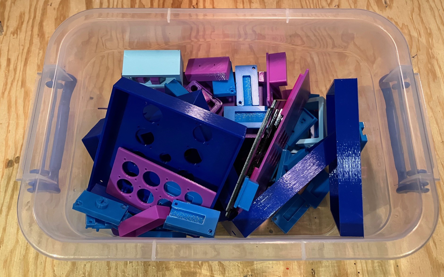
Smooth Sailing, NOT
10/15/2023 at 15:32 • 0 commentsI was tidying up my work area and was not surprised to see quite a bit of waste. This feels about average for one of my projects.
While I try to think ahead when I create my designs, the truth of the matter is I tend to end up working pretty iteratively. I seems that the great ideas for next steps often don't come to me until I have a physical manifestation of the current step. Fortunately filament is fairly inexpensive, I just wish there was a better way to recycle my PLA cast-offs.
-
Even More Stabler
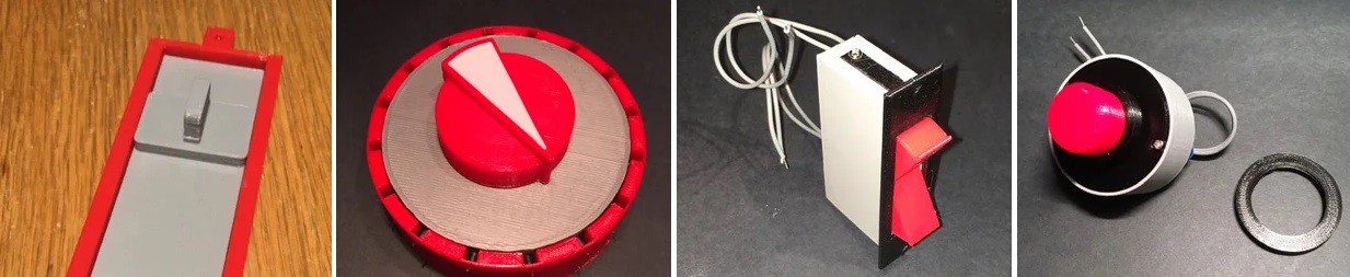
10/14/2023 at 23:04 • 0 commentsThe Tile Holder Button (THB) I'm using in this project is not my first attempt at making my own switches (slider, rotary, rocker, button). (Actually the THB is more a case of making an existing switch my own.)
The common thread in all of these designs is that I put a lot of effort into the look and feel of the finished product (oh and magnets ;-).
So even with the stabilizer added, pressing the tile button still felt a little "mushy", which was a marked improvement over "loose" and "floppy" without the stabilizer. Furthermore the grating sound of the 3D printed THB brushing against the 3D printed rectangular hole in the top of the MacroPad was annoying, exacerbated by the fact that the layer lines go in the same horizontal direction for both. This also makes pushing the THB feel "rough".
To mitigate the scraping noise/feel I tried making the rectangular hole a little bigger, but this just gave the button more room to flop around in, and did not completely remove the grating problem.
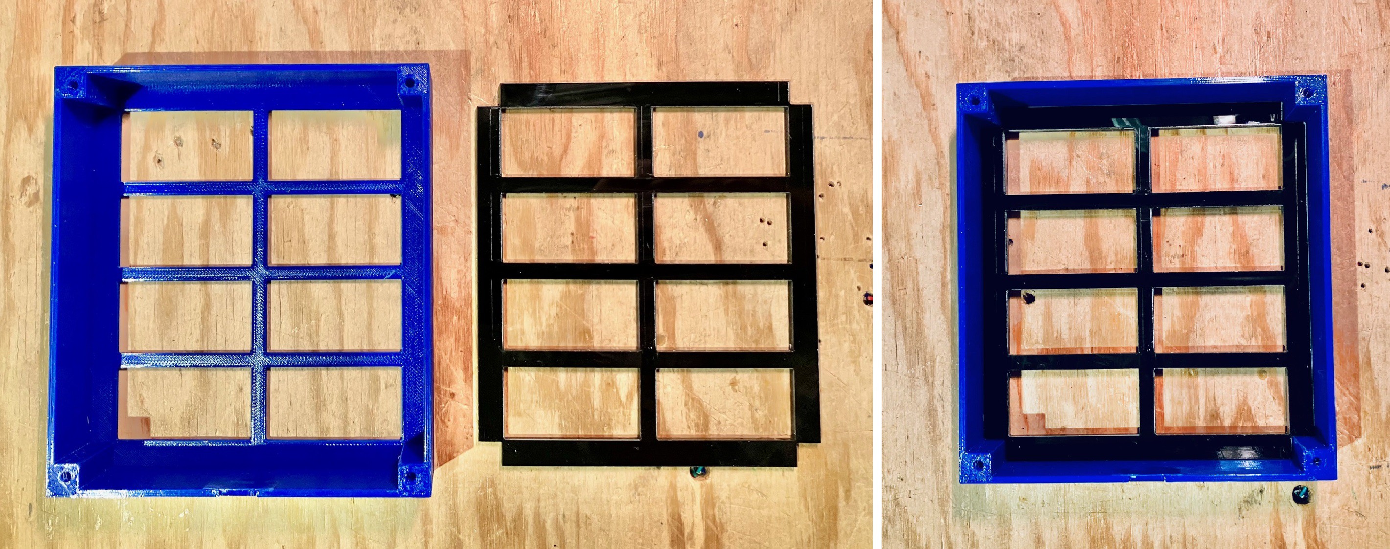
In an effort to work around the layer lines on the top panel rectangular holes, I laser cut a piece of 3 mm acrylic to fit into the top panel.
Since the top panel holes were a little too big anyway at this point, I made the acrylic sheet holes smaller, pretty close to the actual tile holder dimensions. This made a big difference. The grating feel/noise when pushing a THB was significantly reduced, but not eliminated unfortunately. Furthermore since the acrylic hole was smaller the mushiness was eliminated.
On the tile holder side I tried wrapping some clear tape around the part that sticks up through the top panel and the grating noise is gone too. Now I worry about the long term durability of this solution so I am looking at alternatives:
- Applying clear acrylic paint to the sides of the tile holder.
- Printing at a much finer layer height (.07) to reduce the layer lines.
- More durable heat resistant waterproof tape.
One other thing I noticed while working through these issues was that the THB could be pulled up through the top panel pretty easily, dislodging the stabilizer wire. So I added a "retaining ring" to prevent this and hold them firmly in place with the top panel attached.
With the "feely" issues out of the way, I can now see my way clear to finish the remaining Tile Holder Buttons and wrap things up here.
-
Stabilizing
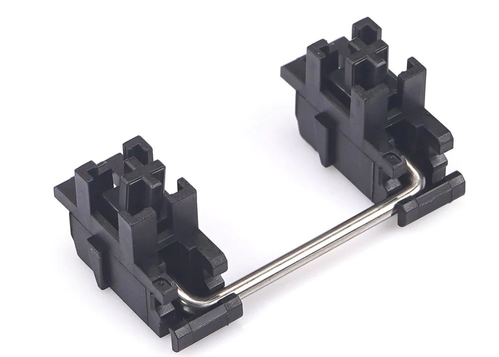
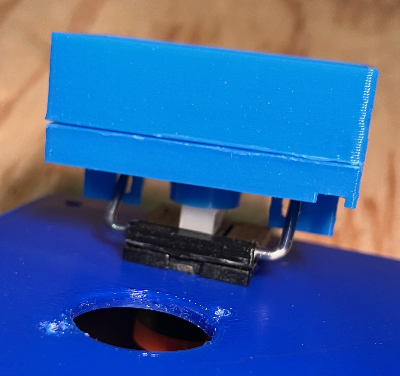
10/12/2023 at 23:39 • 0 commentsI did a quick test of the Tile Holder Button that I put together and mounted it on one of the Fubata MD-4PCS switches. Needles to say given that the Tile Holder Button is much heavier and larger that a standard 2U keycap it felt pretty "loose" or "floppy". In most cases even standard 2U keycaps use stabilizers like these shown below to give them a solid feel.
In fact I had a set of stabilizers similar to these, but unfortunately I could not make them work with my big ass buttons, but it occurred to me that I might be able to just use the stabilizer wires. So after a few false starts I modeled the following parts:
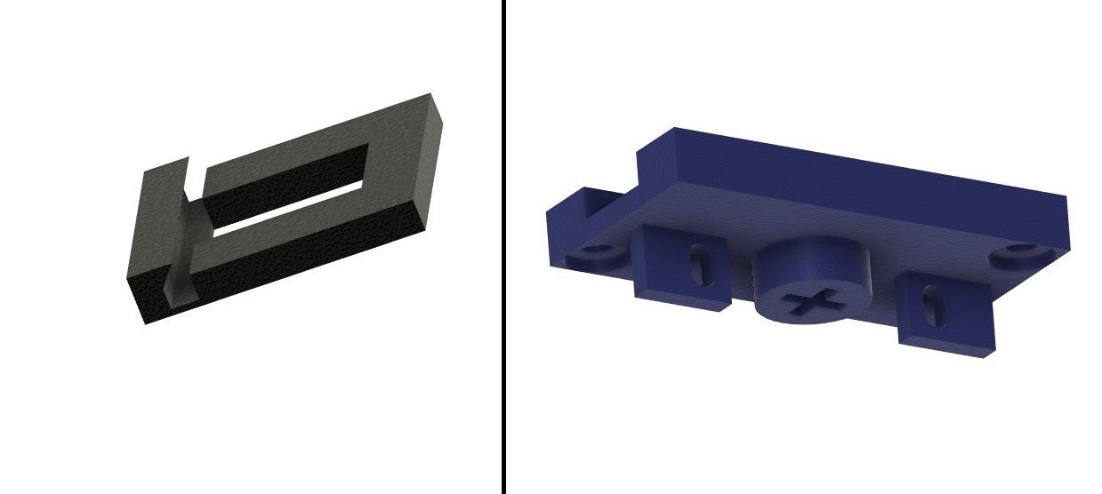
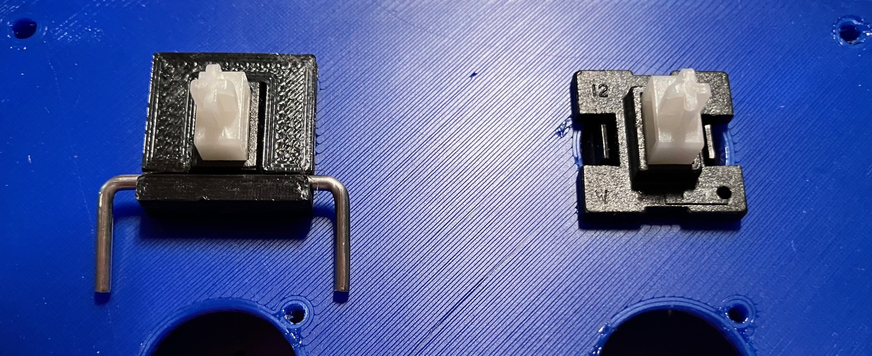
On the left is a cap to go on top of the Fubata switches to hold the stabilizer wire. To the right you can see the modifications I made to the Tile Holder bottom piece adding the drop down panels with holes to accept the stabilizer wire. To set this up, first glue the stabilizer wire holder cap to the switch (left below). When the glue dries snap in the stabilizer wire.
Then it is actually pretty easy to slide the two ends of the stabilizer wire into the holes I made in the Tile Holder bottom while pressing the button onto the switch's MX (+) connector.
Now I will be the first to admit that my DIY stabilizer is not nearly as good as those commercially available, however the button feel is significantly better with than without, so I consider the effort to be worth while.
-
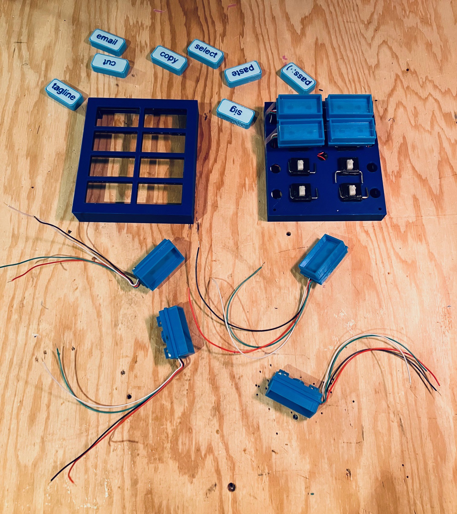
Wiring (Part 1)
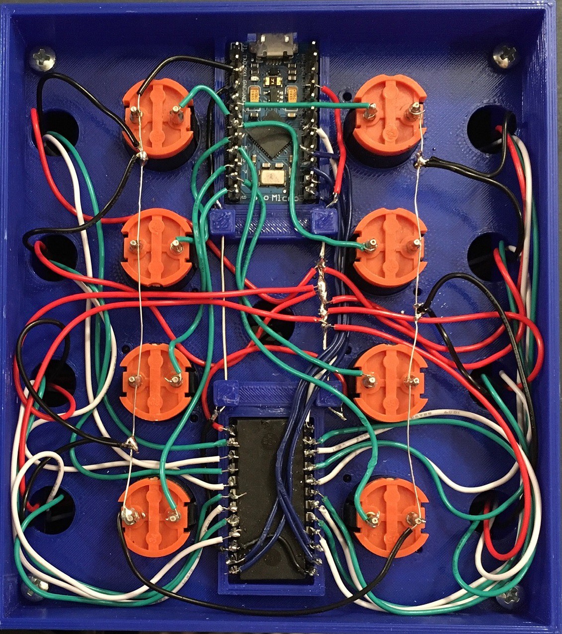
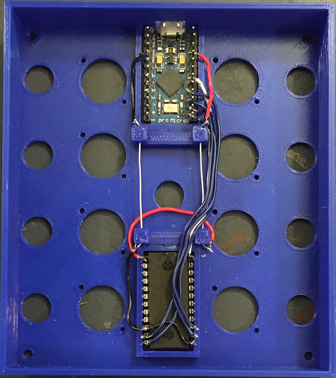
10/11/2023 at 22:25 • 0 commentsI decided to take a break from making tile holder buttons and start wiring everything else. I started by adding a little power bus (a couple of bare 22 AWG wires) between the pro Micro and CD4067BE 16-Channel Analog Multiplexer. Then I wired the 4 outputs from the pro Micro to the channel select inputs of the multiplexer and the multiplexer output to an analog pin on the pro Micro. I used 28 AWG wire for all connections.
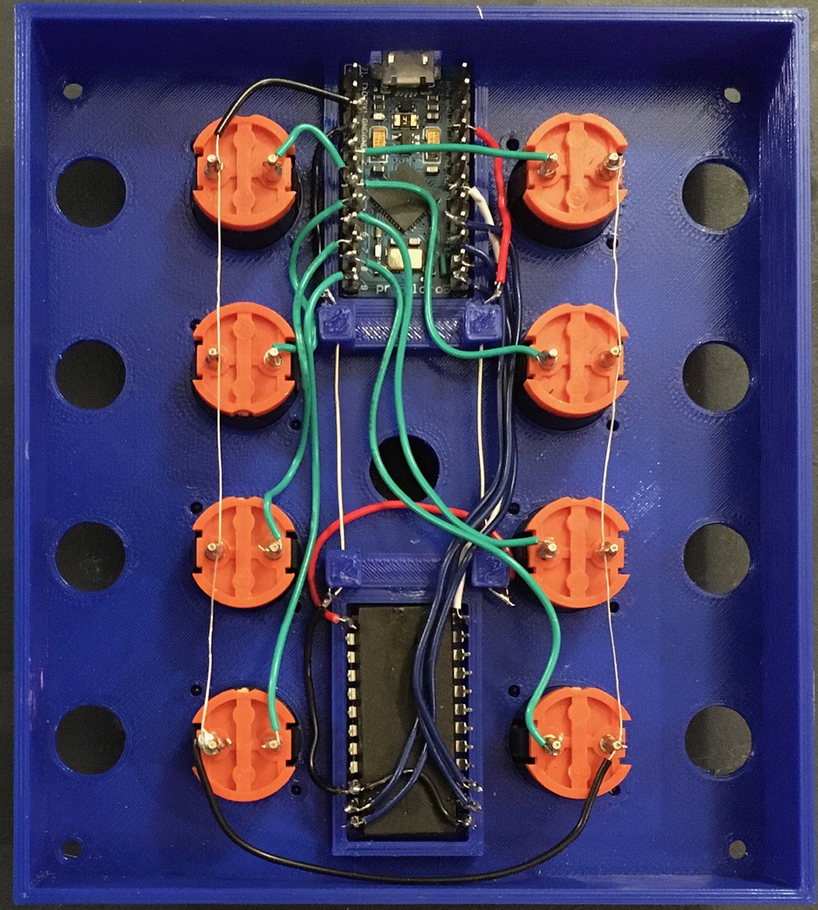
I inserted the eight Fubata MD-4PCS switches and wired one lead of each to ground. Then I wired the buttons to the 2-9 IO pins of the pro Micro.
Here are all the connections so far.
Arduino pro Micro CD4067BE Multiplexer Wire Color Other VCC +5V Red Also powers the sensors. GND GND Black Project Ground A0 Common Input (Read the channel selected by S0-S3) White I/O Pin 2-9 Green Button 1-8 I/O Pin 15 S0 (These four outputs select which of the 16 analog channels to read.) Blue I/O Pin 14 S1 Blue I/O Pin 10 S2 Blue I/O Pin 16 S3 Blue GND E (This is an inverted chip select pin.) Black When I finish the tile holder buttons I'll wire the rest.
-
Testing The Tile Holder Buttons
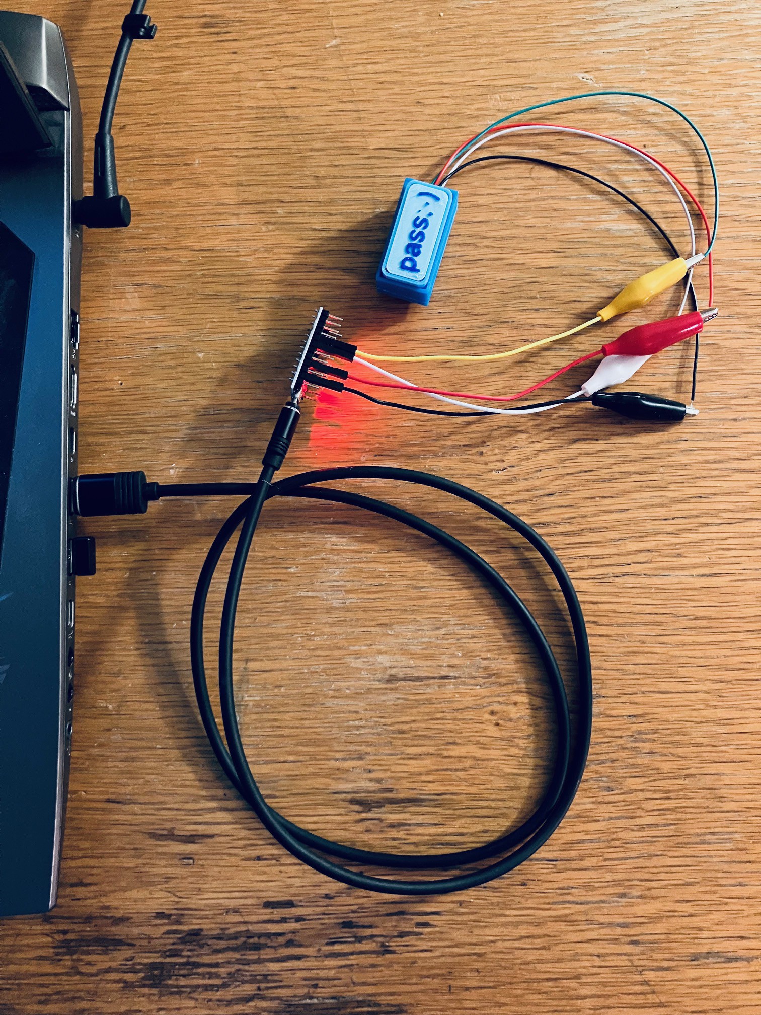
10/11/2023 at 00:59 • 0 commentsBefore I start soldering in the tile holder buttons I want to make sure that they are working as expected. So I setup a pro Micro with a little wiring harness and a simple sketch to test both of the sensors. Here is the tile holder button that I just made wired for testing.
The sketch is very straight forward.
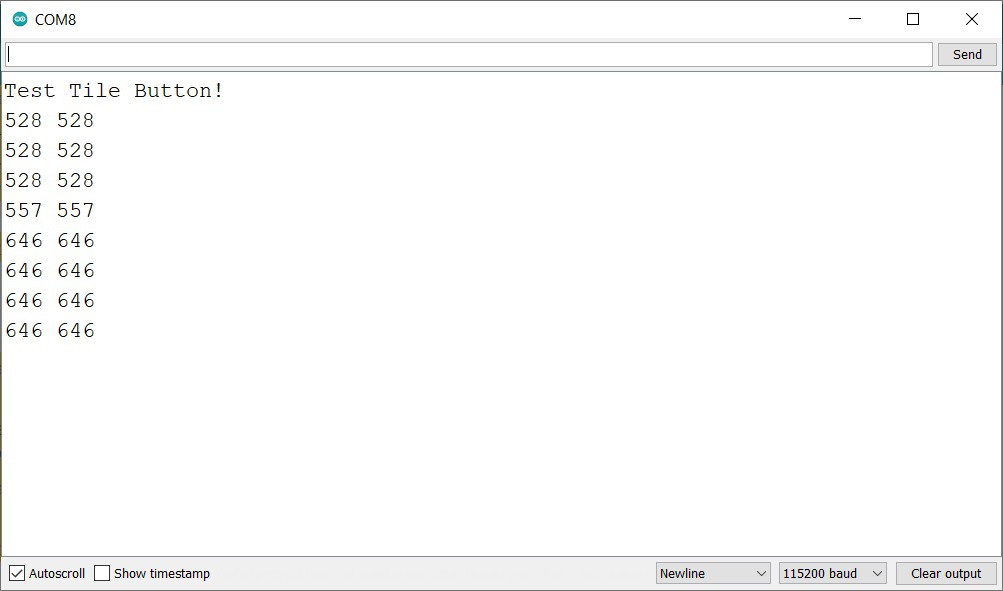
int sensorPin0 = A0;   // Hell Effect 0.
int sensorPin1 = A0;   // Hell Effect 1.

int sensorValue = 0;  // variable to store the value coming from the sensor

void setup() {
  // Setup serial output.
  Serial.begin(115200);
  while (!Serial) {
    delay(1000);
  }
  Serial.println("Test Tile Button!");
}

void loop() {
  // Read the value from the first sensor.
  sensorValue = analogRead(sensorPin0);
  Serial.print(sensorValue);
  Serial.print(" ");
  // Read the value from the second sensor.
  sensorValue = analogRead(sensorPin1);
  Serial.println(sensorValue);
  delay(1000);
}
It just emits the readings from both sensors once a second to the serial monitor.
I started it with no tile, then dropped a [0-0] tile in. You can see the change in readings indication all is well with this button. Next.
MacroPad With Tile Buttons
As a quick follow-up to my “A Tile Based MacroPad” I present an alternative.