Yet Another MW Radio - The Audion
Another super simple medium wave radio.
This time a Franklin Audion (synchronous detector).
Another super simple medium wave radio.
This time a Franklin Audion (synchronous detector).
To make the experience fit your profile, pick a username and tell us what interests you.
We found and based on your interests.
Well I assembled and tested the noisy regen today:
Performance wise with the short antenna it was a little better than the first one. With a long antenna not as good. Selectivity was better (likely due to the higher input impedance as a result of lower collector currents).
Exciting? No. The reflex circuit was much better (but then I used a proper coil). Would I recommend it? No. Is it all the coil problem? No, I don't think so. To get an idea about how bad this receiver is, without the high gain audio amplifier you would not hear anything. I suspect a Ge diode followed by the same audio amplifier would work better!
Here is the layout:
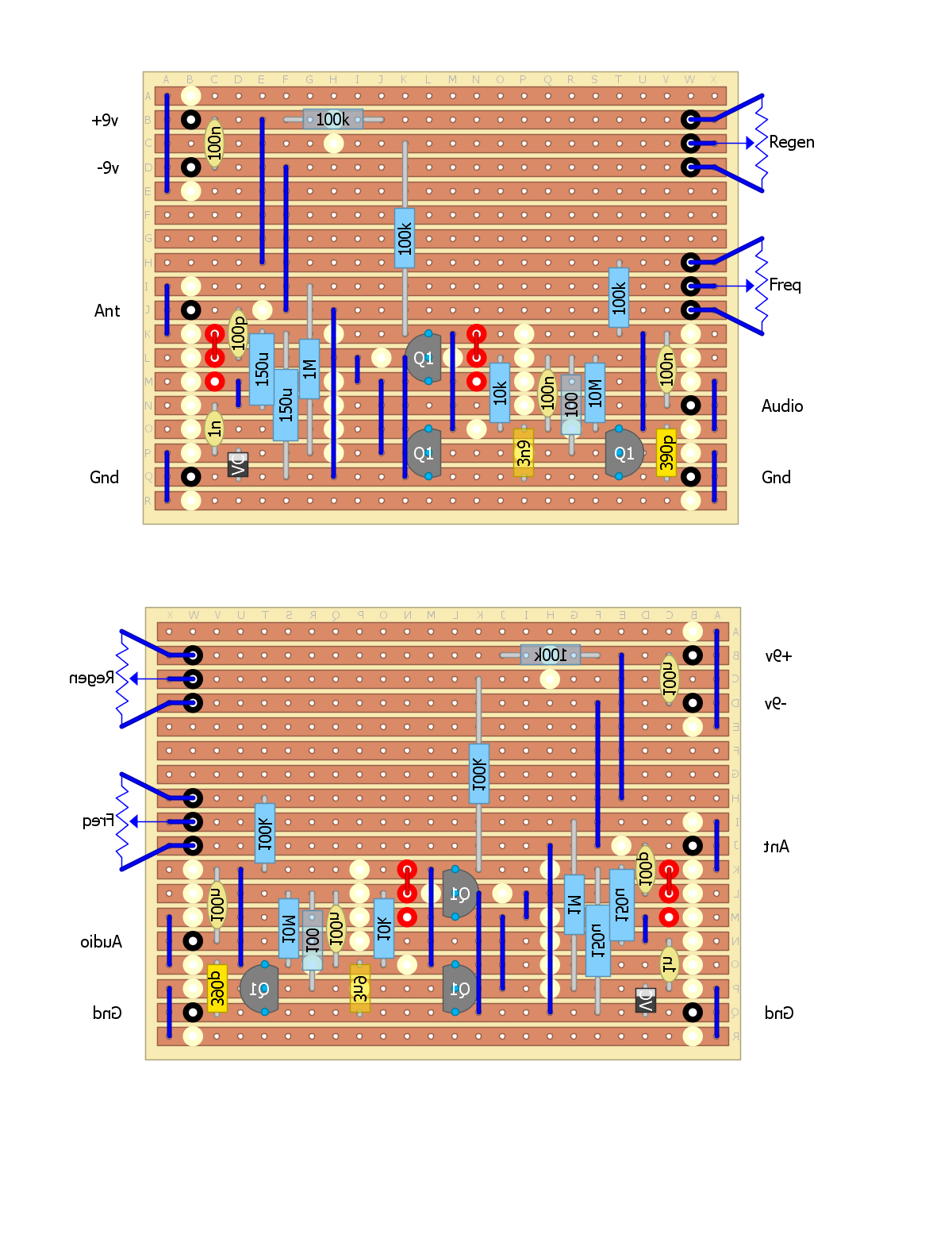
Regards AlanX
Alan Yates (http://www.vk2zay.net/article/128) has stripped down the Franklin Audion circuit to its basics and taken the audio off the emitters rather than the tuned circuit. This seems to make more sense to me:
(Note that the 47n output filter capacitor should be 4.7n!)
So I stripped my circuit down and was able to get the simulation to honour the expected frequency locking and demodulation:
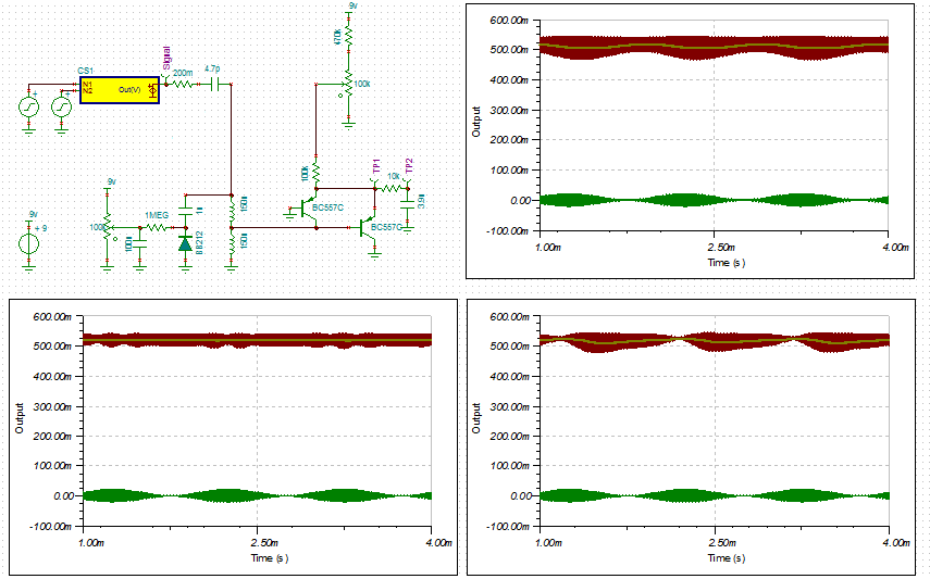
The green is the input signal, the red is the oscillator and the yellow the output audio.
Note how the oscillation can be quenched in case 2.
---
Now that I have a working simulation I can test component values. Or in this case the component value the 100k emitter resistor. You may have noted I increased the value from 10k R to 100k R in this version. The results indicate that the same operating point can be found with the 10k resistor as the 100k resistor. The main difference is that the oscillation amplitude can be much higher (the full available collector voltage or about 0.7v pp) and consequently the available mixer gain (i.e. higher audio output). This is reflected in actual use. The oscillator frequency also shifts with higher oscillation amplitudes.
Using the higher (i.e. 100k R) emitter resistance will tame the receiver. Audio gain is best found elsewhere.
---
Added the schematic to help show how the oscillator works:
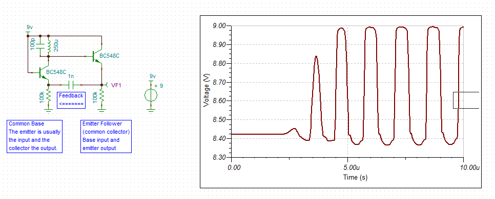
I have used NPN transistors (as this is what most people are used to) and split the emitter resistor to show the two transistor amplifiers.
---
Here is the updates strip-board design:
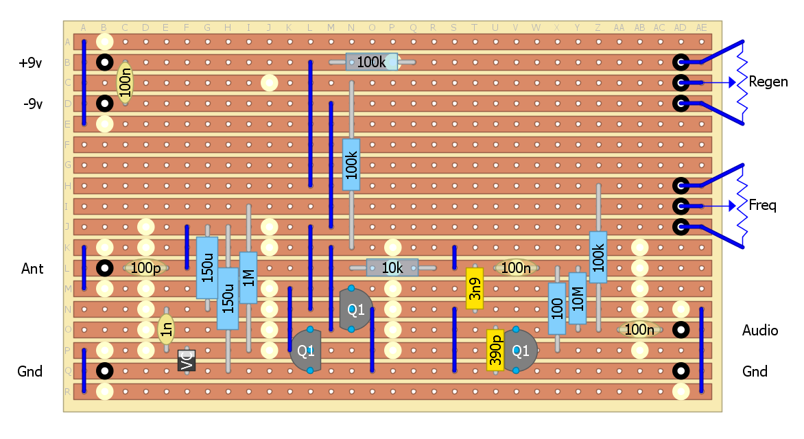
If you are interested, the input impedance of the Franklin oscillator in this circuit is about 1.2k (approximately that of the coil impedance tap) and the output is about 10k (approximately the same as the low pass filter).
----
Although I have had success with the lumped inductors, I know the Q is quite low.
But how good or bad are they? That depends on the wire diameter and core material.
An Internet search suggests that they roughly match the Vishay IRF-24:
Now a Q of 60 is far less than 300 to 500 you can get with an air coil.
For MW (i.e. 1 MHz) a Q of 60 translates to an unloaded bandwidth of 17 kHz.
Which is why they work in this application although not great when the coil is loaded.
The alternates are:
I have designed and built MW radios using the first four options.
Using the data from an Amidon datasheet for their mix 61, the maximum Q is about 270 (between 1 MHz and 2 MHz). This is the best ferrite material for MW frequencies.
Options not tried:
Option 2 seems to be the best for a PCB mount but the toroids are a few weeks away (just orded them on ebay).
AlanX
Using a 4 foot wire aerial the radio worked but not very loud. Regeneration was smooth and sound quality was good. The circuit Q is pretty poor and regeneration only improves the Q to a limited extent. I was not that impressed! Here it is:
Hooked up a 14 m aerial (no earth) and the volume was quite loud. Clearly, the "detector" is not that sensitive (need a strong signal to perform). There is a design which has AGC, now I know why:
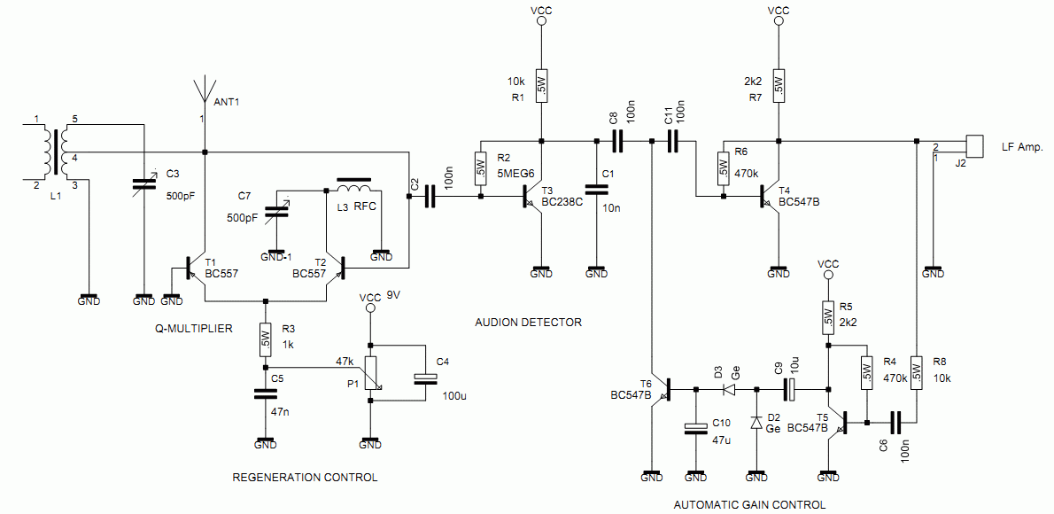
I was thinking it may be better to take the audio off the emitters rather than from the coil tap. I found an example at http://www.vk2zay.net/article/128:
AlanX
Often radio circuits have coil taps and/or coil couplings. These be simplified as lumped inductors.
For example a 50% tapped 200 uH inductor is the same as two 100 uH inductors in series with regard to LC oscillation frequency and impedance transformation. The main down side with lumped inductors is that for similar coil construction the total resistance will be higher, that is the Q will be lower (i.e. a 200 uH inductor needs only 41% more turns than a 100 uH inductor).
So my tapped 320 uH coils consists of a 100 uH and 220 uH inductors in series. The simulation suggests a frequency range (using a BB212 varicap diode not the 1SV149 diode) of 1.27 MHz (for an 8 volt control voltage) and 564 kHz (for 1 volt control voltage. Note the series resonance response and "roll-up"!:
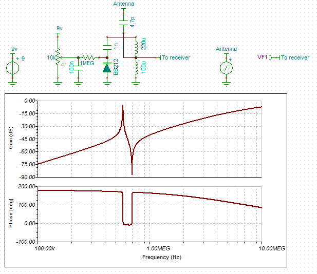
This is half way between the 25% and 50% taps shown the the schematic:
Modelling a coupled coil has no series resonance response and a normal "roll-down":
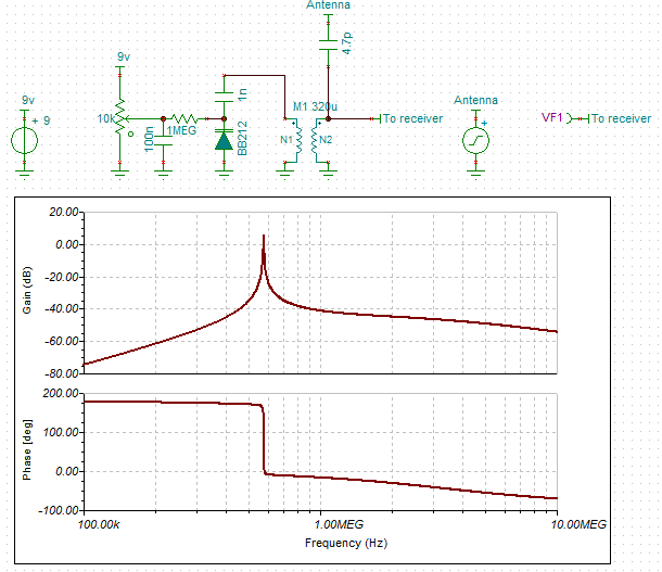
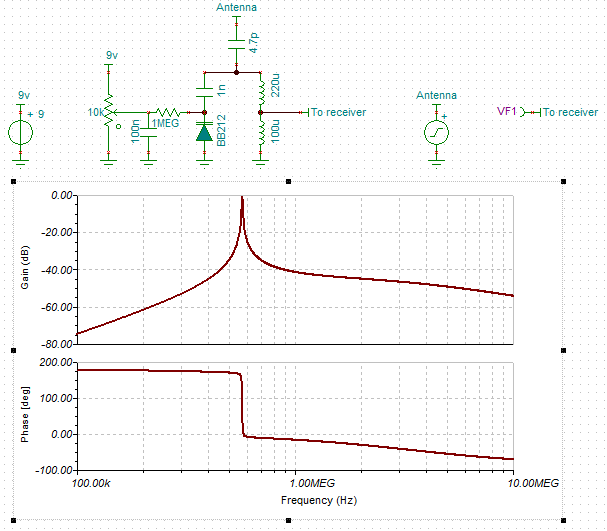
Changing the coupling produces a normal response:
I was rummaging through my junk box looking for some inductors and came accross an old super-regenative tube radio I build in the mid-nineties. I used the lumped inductors then and this receiver worked okay:
Here is the schematic:
AlanX
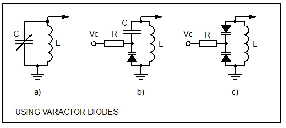
I have not used one before but my reading suggests that they work pretty well as a "single" in receiver projects (refer to "B") but for (high powered) oscillators a "twin serial" set up (refer to "C") is recommended:
(source: www.jestineyong.com/wp-content/uploads/2014/09/varactor-diode-checking.jpg)
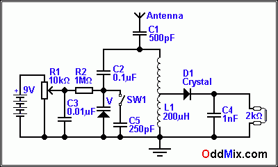
In each case value of "R" is not critical but 1M ohm is common. Usually a capacitor at "Vc" is added to minimise unwanted RF in the control voltage (Vc) circuity as shown in the following:
(source: www.oddmix.com/tech/px/cr_varactor_crystalset_f1.gif)
I purchased a couple of these some time ago off ebay. There is the datasheet (http://www.qsl.net/df7tv/datasheets/1SV149.pdf). At 1 volt the capacitance is about 485 pf and at 8 volts the capacitance is about 25 pf.
Using a 320uH inductor and a 1000 pf series capacitor the tuning range should be about 500 kHz to 1.8 MHz.
Regards AlanX
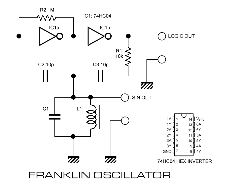
The Franklin oscillator is a little strange and not immediately obvious how it works:
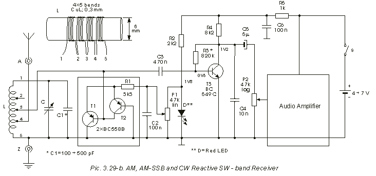
The following helps a lot:
 (source: www.radiosparks.com/images_d/Franklin Oscillator.png)
So positive feedback at parallel resonance (0 degrees phase shift).
The next image is a transistor version:
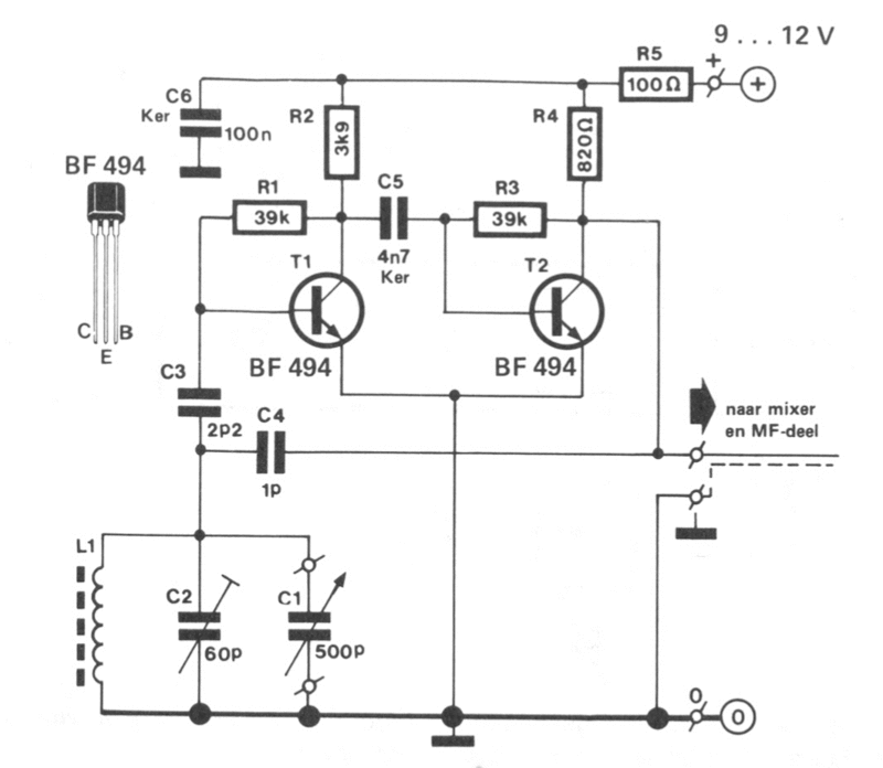
(Source: www.uploadarchief.net/files/download/franklinoscillator.gif)
Here is a rationalised (long tail pair) FET version:

(source: www.uploadarchief.net/files/download/osci.png)
Still it takes a leap of faith to get to here:

(Source: i178.photobucket.com/albums/w269/notxyl97/DL7MWNQ-Multiplier.png)
But at low voltages most of the biasing components can go!
AlanX
Create an account to leave a comment. Already have an account? Log In.
This is an interesting project. It's great to not just get a circuit, but to also view the process, including tests, analysis and refinements.
I do respect the goal of eliminating the air-coil and traditional moving-plate tuning capacitor. But a big part of the "magic" of old regenerative receivers is how freaking good they work, just using a handful of components, and how the performance was enhanced by the optimization of a component or two, such as going from a simple tube coil to a spider-web.
I encourage all serious radio enthusiasts to build at least one simple tube regenerative receiver, to experience what your grandparents or great grandparents had, almost a century ago. It's fun, and it makes a great (and useable, and possibly handsome) benchmark receiver to compare newer designs against. The parts are still available, or salvageable from old stuff.
As an example, I've built the optimised version of this simple receiver which only needs around 12 to 20v for the plate circuit. http://members.iinet.net.au/~cool386/kits/ace.html
Hi AC,
Yes the air-coil is magic. I quite like spider coils.
Really the lumped versions are to speed up the prototyping cycle and to encourage others to try.
Here is my final version of the Reflex MW/AM receiver based on two transistors:
But the woodwork took longer than the electronics to make!
---
In the mid-nineties I did build a tube super-regenerative that worked okay.
As I did not understand tubes with more than three connections (excluding the filament), I used a 12AT7A. As the saying goes, a Tube is a FET with a pilot light!
Here is the schematic:
And here is the board:
I was working on a Tube reflex receiver using a 1D8 back then but a dodgy RF choke stopped me from getting the it working
Regards AlanX
> As the saying goes, a Tube is a FET with a pilot light!
... awesome
Ah nice, this reminds me of the time when I used to build detector radios. Later on, I used this: https://en.wikipedia.org/wiki/ZN414. This post also motivated me to get an old AM radio from the basement: all I can hear now is static, and noise from e-things doing something at a rate of 530KHz to 1.6 MHz. Building a 1W AM pirate radio station might be viable these days ;-)
Hi Thomas,
I remember the ZN414 from the 70's and 80's. Later replaced by the MK484.
You may have noticed I have a discrete transistor bent thus my version of a ZN414 is:

Regards AlanX
Hi AlanX, nice! I guess I'd have to run your schematics through a simulation to understand why Q1 is biased just right and how the demodulation works. I've looked up the MK484, and it's nice to see that such a component for simple applications still have their place in the market!
Hi Thomas,
Referring to your last post:

Q1 looks like a common base amplifier with an LC between the collector and base (grounded) and a resistor between the emitter and supply. Basically Q1 is in saturation.
The base and collector have the same voltage at DC (ground). With a signal across the LC, the base voltage is only amplified on the negative excursions (i.e. it is a diode with gain).
Q2 is a common collector. The voltage on the emitter resistor is feed back the the Q1 base and/or the LC.
AlanX
Hi Thomas,
A better explanation of how the common base and common collector (emitter follower) Franklin oscillator works. I use NPN transistors as it works better for me:

Note: Before the oscillator saturates (in the wave form), the second pulse is a rectified sine wave.
If we keep the feedback down then it becomes an oscillating rectifier (free diode!).
And we can take for granted that the oscillator will follow an input signal within limits.
Now we have a synchronous mixer. The input signal will be demodulate as the transistor gain varies with collector current:
Beta = log10(2/1000)/log10(Ic/1000)*Beta(@2mA)
Regards alanX
Hi Mark,
Not sure it is an Audion, in the simulator it oscillates easily, somewhat distorted at the threshold. I cannot get it to lock onto the input frequency and zero evidence of demodulation (except in the audio amp).
I cannot actually see how it can demodulate the signal. Neither switching nor non-linear.
Perhaps it just adds the synchronous oscillator to the signal and it gets mixed in audio amp.
But simulators are pretty bad at modelling this behaviour.
---
Checked the junk box and I have what I need (with a few substitutions) so I will report back on how it goes tomorrow.
---
AlanX
I have not seen the word "audion" since I had my vintage radio collection years ago, and then I was working with UV201A triodes :-)
Good idea. I wish varactors/varicaps were more widely available. Especially high-capacitance/low voltage ones.
I really have to start making radios again - especially now while it's quiet here - it must be your season for atmospheric noise now?
Become a member to follow this project and never miss any updates
By using our website and services, you expressly agree to the placement of our performance, functionality, and advertising cookies. Learn More
 Andrea Console
 agp.cooper
 DeepSOIC
 Marek Materzok
Hi AlanX
and other interested in this topic.
I have tryed to build this circuit.- by schematic given by AlanY
with transistors BF506 - yes i have them from old TV tuners.
But no mather what i change receiver not respond.
From what i have forund this is so called PELTZ oscillator type and
not Franklin but that is not important.
It looks to me that version you get to work is with NPN transistors
so what to use from junk-box ?
I would like to know is there a way that this radio work from 3V - 1x1.5V battery
and i see some circuits similar to that .
Any suggestion or help?
thankx!