-
What are we actually measuring here?
05/05/2024 at 19:08 • 1 commentAfter all is said and done, the sensor measures about a 6 ns difference between a dry sensor and one dunked into about 4 inches of water. That's certainly enough to measure since the sensor has a resolution to about 10ps with an accuracy of closer to 80ps (just rough guesses), but considering the reflection on the 7 inch dry trace in theory is only about 2ns, that difference is pretty large. Looking at the relative permittivity of pure water, delays of that magnitude are theatrically possible since a wave traveling thru 7 inches of water would see about a 10.5ns reflection. However seeing a 6 ns change would require a huge shift in the effective dielectric constant of the probe in water, which seems unlikely. So what is actually being measured here?
Lets take a closer look at a fast step signal down the probe at a much higher time resolution. While I would love to have a 10s of GHz bandwidth real time oscilloscope to do this, I don't have that kind of money, so instead I got access to some vintage hardware. Using a sampling oscilloscope with a 20GHz sampling head and a 30ps step generator, we can take a look at what dunking the probe into water looks like:
![]()
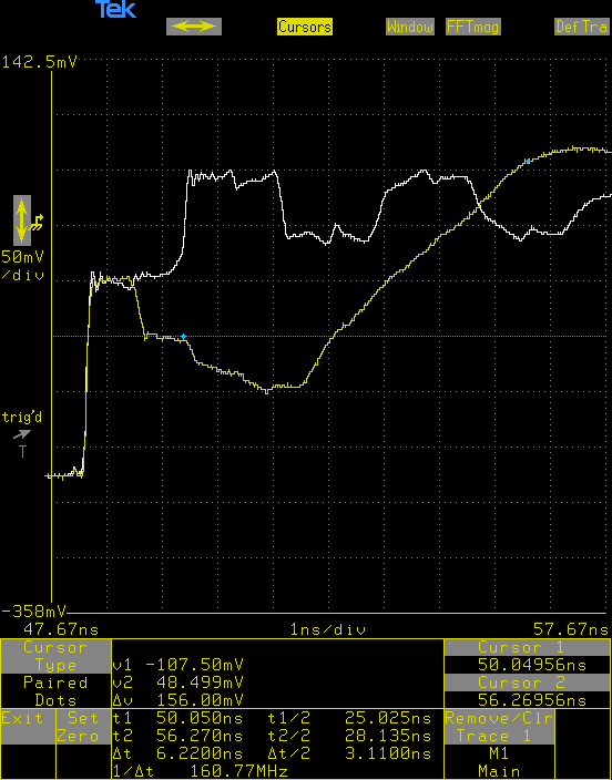
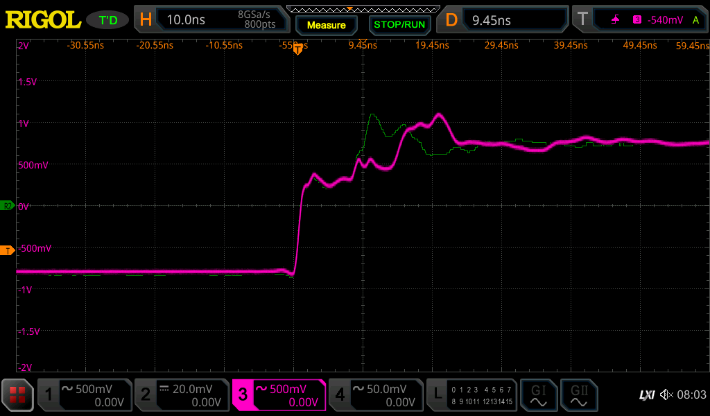
The white trace is the dry probe and the yellow trace is the probe in about 4 inches of water which cover about half the probe. The transition from air to water happens at the first reflection after the step and where the two traces first diverge. The cursor position show the time difference to when the voltage reaches it's peak, so what we are measuring with our sensor. It's also about 6ns, which at least validates the basic operation.
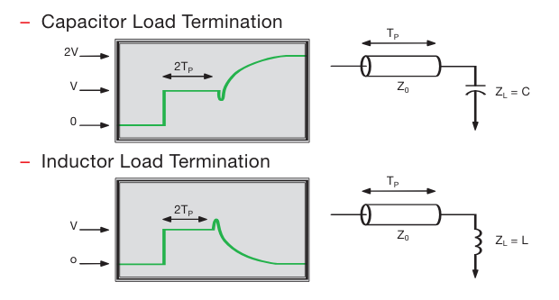
However, the shape of the trace is interesting. Unlike the white/dry trace, where there is a sharp edge at the end (ignore the secondary reflections after 3ns since that's after the signal has first reached the end of the trace), there is a lower section followed by a gentle slope up to the step voltage. This indicates a capacitive termination instead of an open termination
Likely what is happening is there is an increase in the capacitance between the parallel traces in addition to the change in the dielectric constant due to the water. The dielectric constant change is probably responsible for the extended lower reflection in the yellow trace and the capacitance is what is causing slope up to the final voltage. Both of which contribute to the measured delay.
So, while the sensor is based on TDR techniques, what is actually being measured is a mix of effects, much of which is a result of a change in capacitance, similar to what is measured using other soil moisture sensors. That being said, it's still effective and the probe has been robust (no failures in many months), so overall I'm still satisfied with the design.
P.S. Thanks for the comment that made me look into this more, since things are certainly more complex than it originally appeared.
Refs:
https://www.everythingrf.com/rf-calculators/time-domain-reflectometry-length-calculator
https://download.tek.com/document/55W_14601_2.pdf -TDR Impedance Measurements: A Foundation for Signal Integrity
-
Simple Enclosure
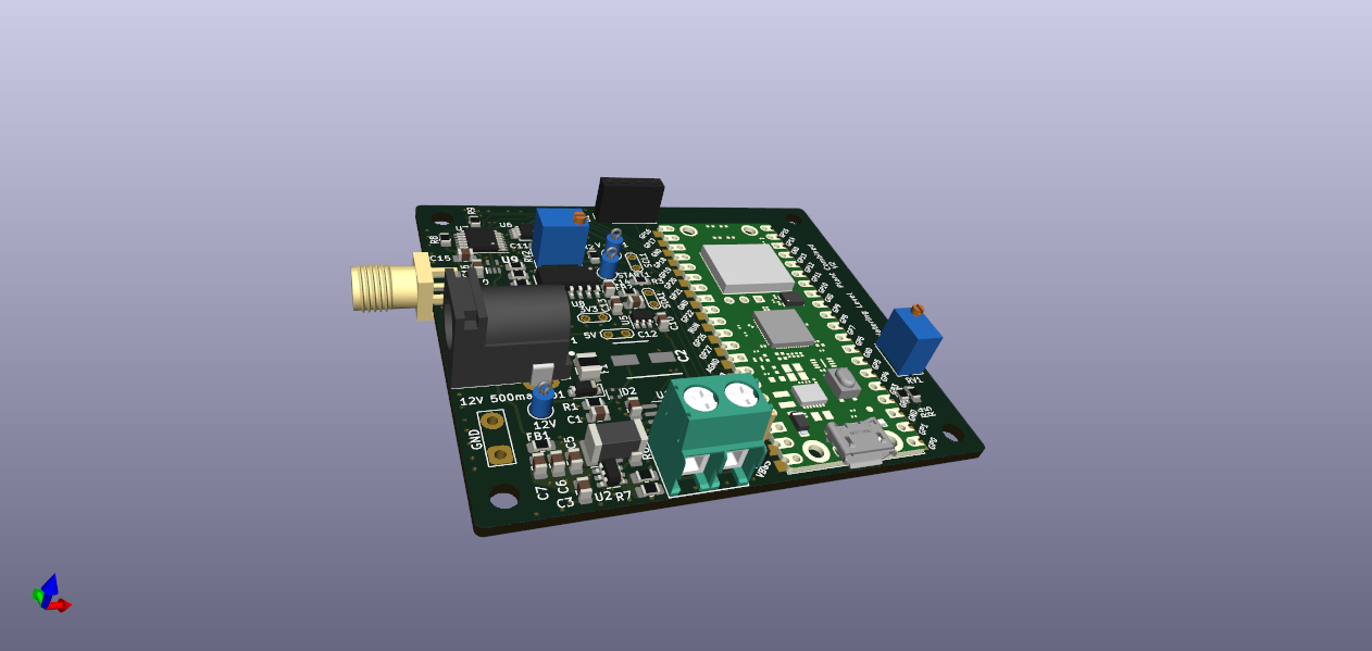
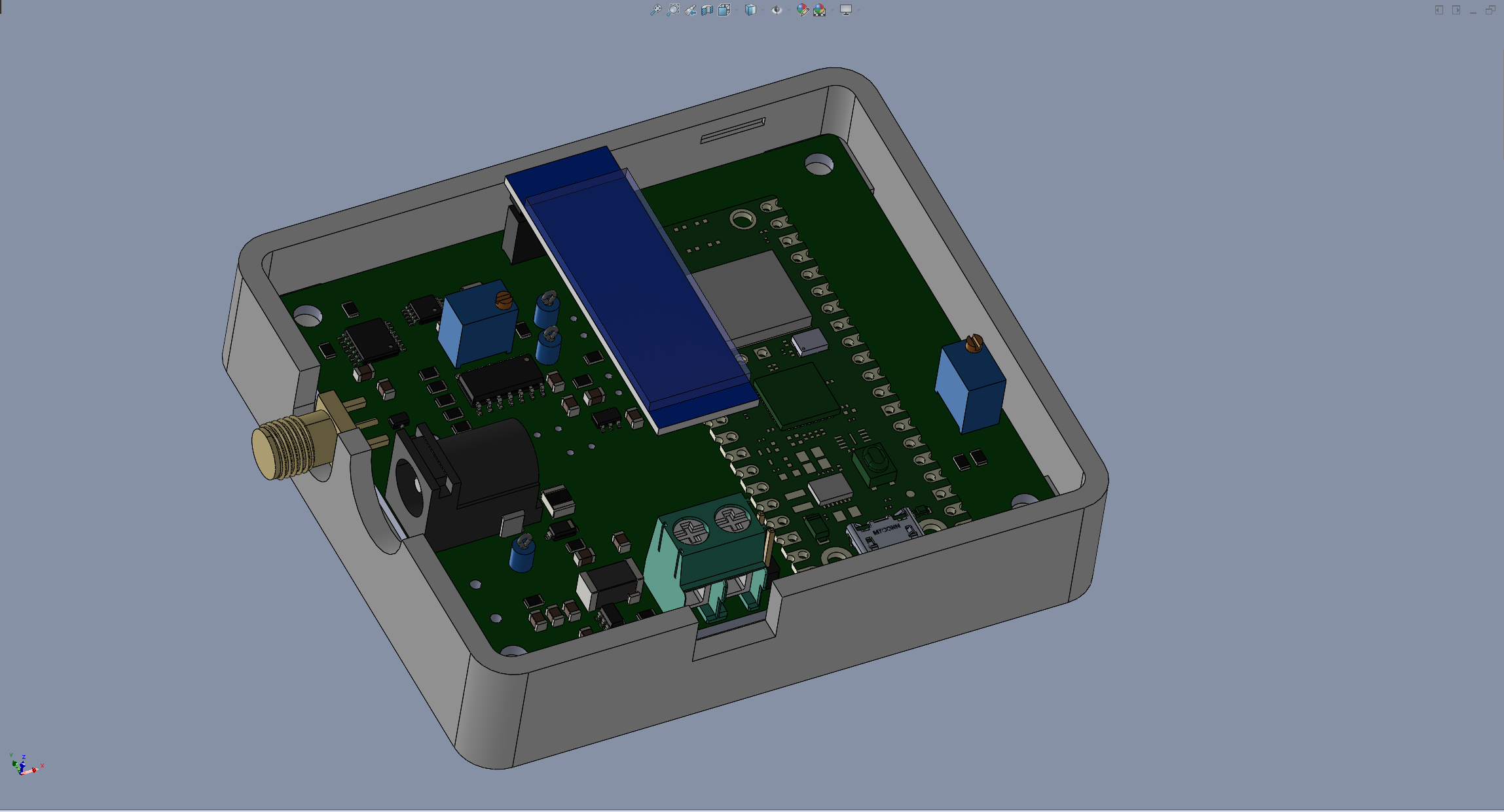
01/23/2024 at 03:26 • 0 commentsIntegrating the PCB with a water reservoir and plant pot would be the best solution, but I haven't quite figured out how I wan to do that yet. So lets just at least put the PCB into a simple enclosure to look a little better since there's been a bare board sitting around for a while now. The board already has mounting holes in it, so I can export the STEP from KiCAD to a CAD program:
![]()
I populated most of the footprints with 3D models mostly via DigiKey or the default models in KiCAD. The only really important ones are the off board connectors so that I can put holes in the right place in CAD.
I also added a simple model for the OLED module I'm using. This is to make sure I put the hole in the top at the right place and have clearance. To make it look actually good, it would probably be best to actually attach the OLED module to the top and use a ribbon cable to connect it to the PCB, but these OLED modules are so cheap on ebay that I just keep a few around to use in these projects.
Under each mounting hole I put in a M3 heat set brass insert and these are easily installed with a soldering iron. If you want a really secure way to hold on the top of the enclosure, use a threaded standoff instead of a screw and then use screw into the standoff to hold on the top. However, a snap fit top will work here and make it easer to get to the adjustments if needed.
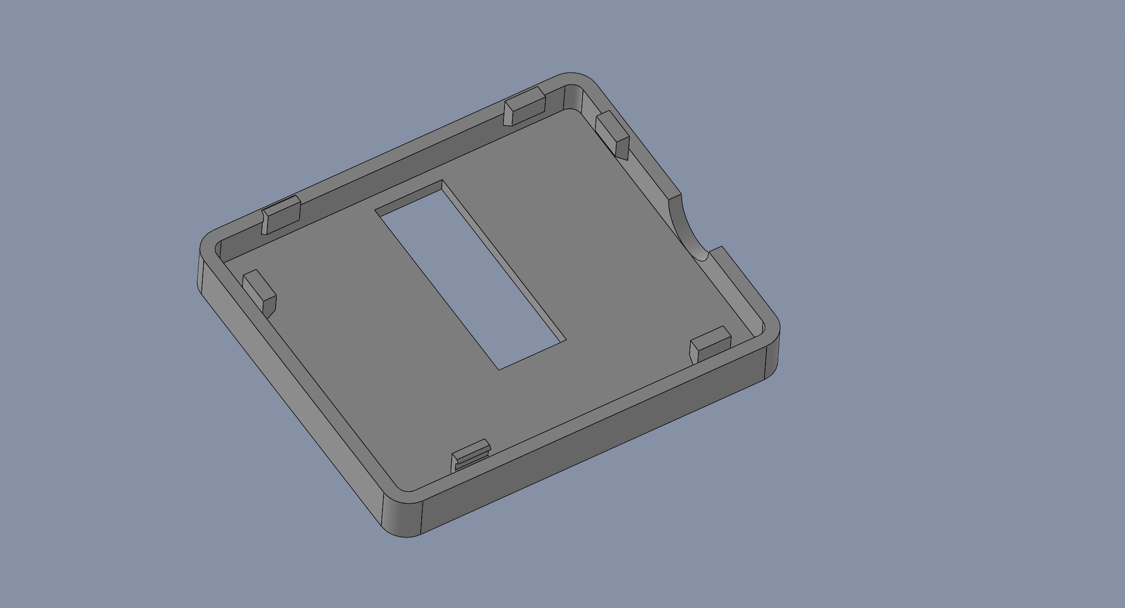
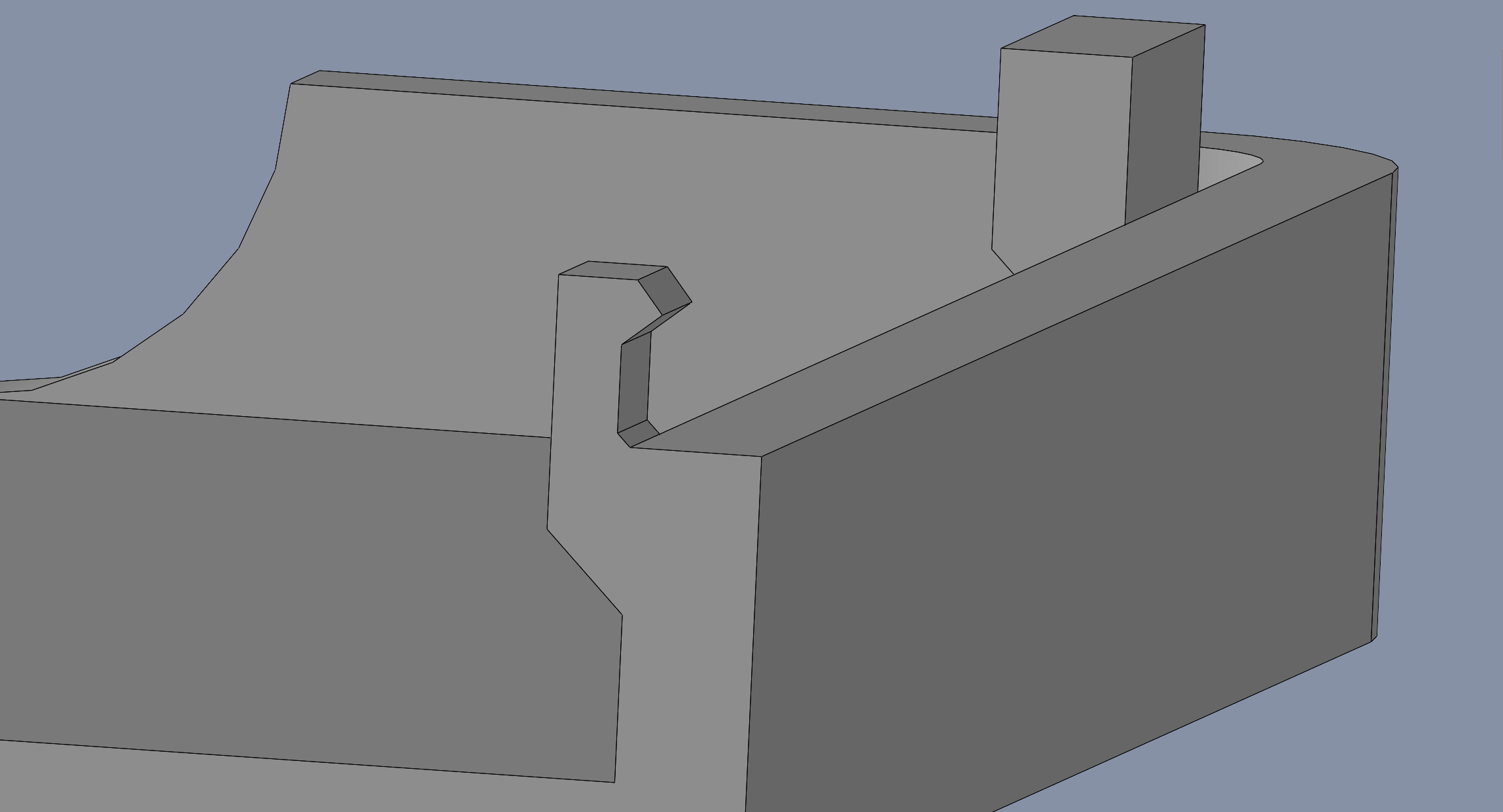
After the first iteration, I moved all the lugs/snaps to the lid so that I could drop the PCB in without having to slid it past things. The snap is only .020" interference as the lid is pushed on and fits into a matching slot in the bottom so that it's not under strain after the lid is closed.
Also make sure to make the snaps fairly wide since 3D printed in this orientation isn't that strong.
An hour and a half later and the 3D print is done:
![]()
-
Fixing SPI with "weak" MISO
11/19/2023 at 21:19 • 0 commentsI was having SPI issues that seemed to be exacerbated by setting a clock speed faster than 2MHz. I was getting junk data from the TDC chip sometimes. So, I kluged around this by discarding values that were outside a reasonable range, but I wanted to address the underlying issue. So, lets dig into what is actually happening here.
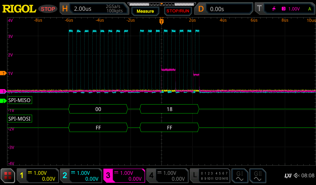
Looking at the SPI transactions with a scope showed a "weak" MISO.
![]()
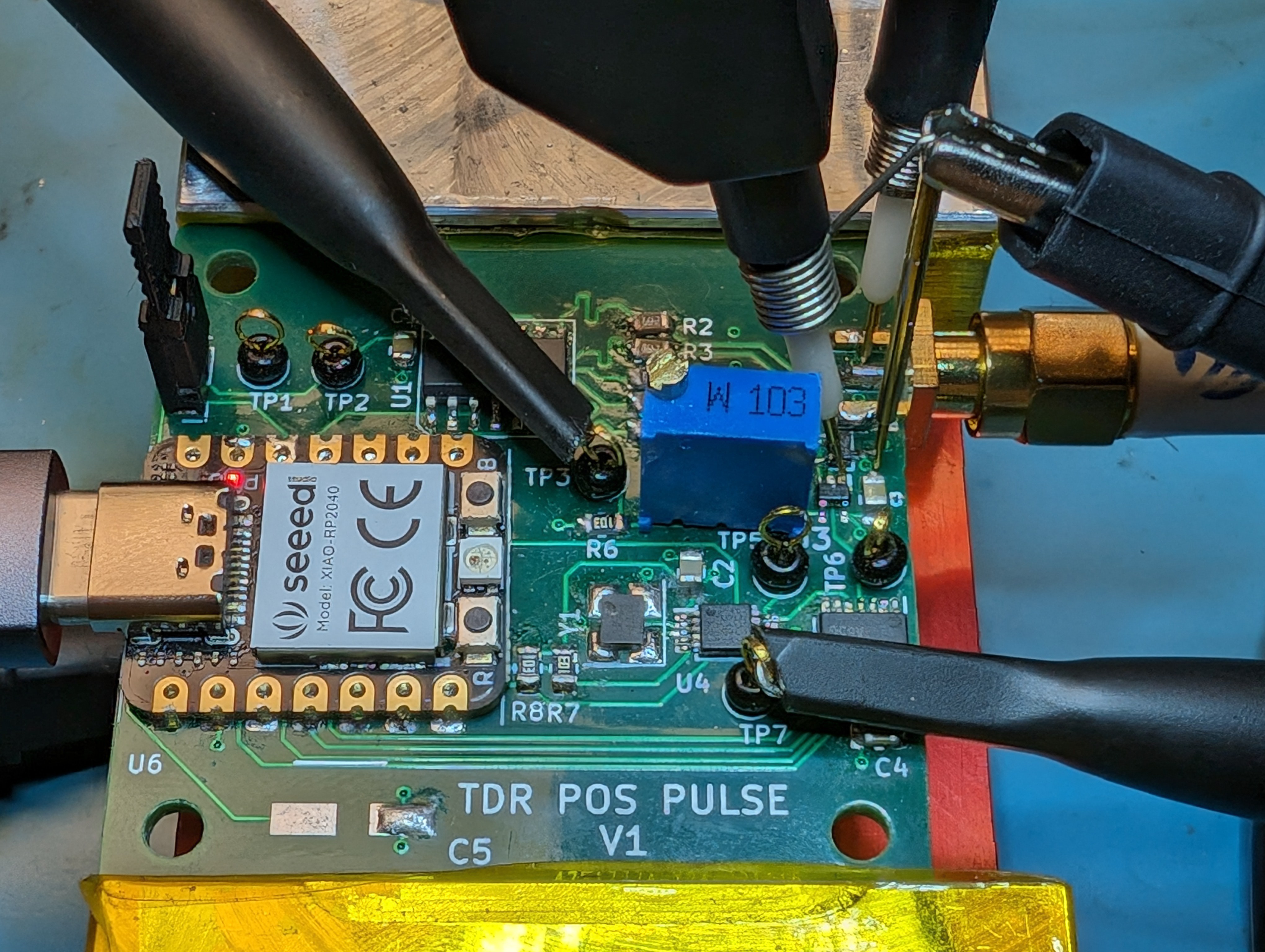
The magenta trace should be going to 3.3V but sometimes doesn't even manage to get to 1V. Just as an aside, always remember to put in test points for signals. The first revision didn't have easy places to probe and it was a massive pain to capture these traces on that board.
To make things even weirder, probing the traces cause more problems. I could see better results when not probing. Just as a test, if I set the clock speed to where it just barely worked, and then when I touched the TDC chip with my finger, it would fall apart. The extra capacitance from the probe or my finger would degrade the signal enough that it would stop working. This is a pretty short, well routed trace so it shouldn't be so borderline.
So does SPI need a pull-up to work? In theory no, but it sure seems like this chip could use some help. But what value to pick? 10K did nothing, but using 3.3K did improve things:
![]()
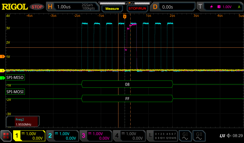
You can see the multiple slopes on the leading edge and no flat top. The pull-up drags the MISO up to 3.3V, but it takes a few 100ns. This is with a clock set to 5MHz (the RP2040 seems to not quite make it there). But if we bump up the clock to the advertised 20MHz
![]()
Here you can see the leading edge takes too long to rise up to the 3V level and the clock already gets to a falling edge where the measurement is made. So, lets try a 1K pull-up.
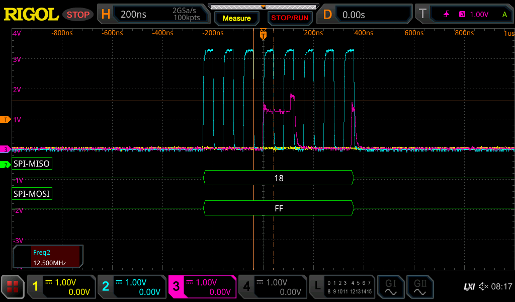
![]()
Now at 20MHz (RP2040 only makes it to 15.6MHz), even the last single bit on MISO can make it up to about 2.7V in time for the falling clock edge. You can also see the TDC starting to struggle in bring the low level down to 0V, but the 0.5V level seems to be good enough to be treated as logic low.
Things still aren't perfect. The TDC should be able to drive the MISO from 0V to 3.3V without that 1K pull-up, but at least this gets it working at 15MHz without kluging around it in software, which is much faster than where it was before. More importantly, it seems more stable, so board to board or chip to chip variations won't mess it up. I've also seen a board that worked at one point start to fail after a few months with SPI errors. Now if I could only figure out why the WiFi sometimes won't reconnect...
-
TOF Sensor CircuitPython Code
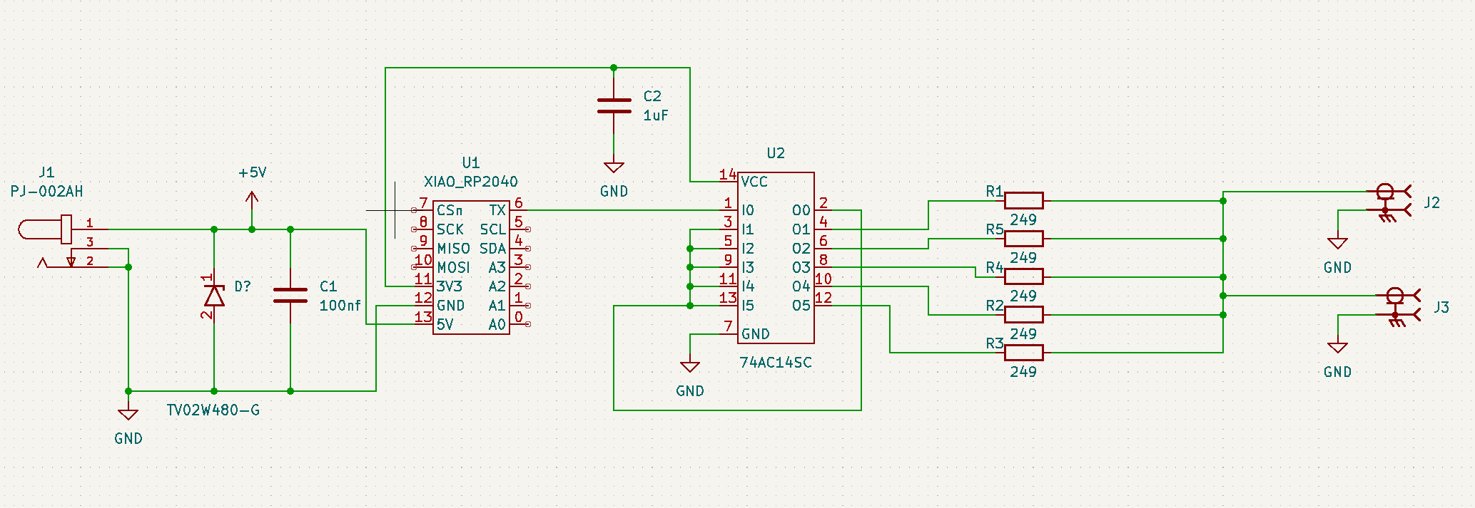
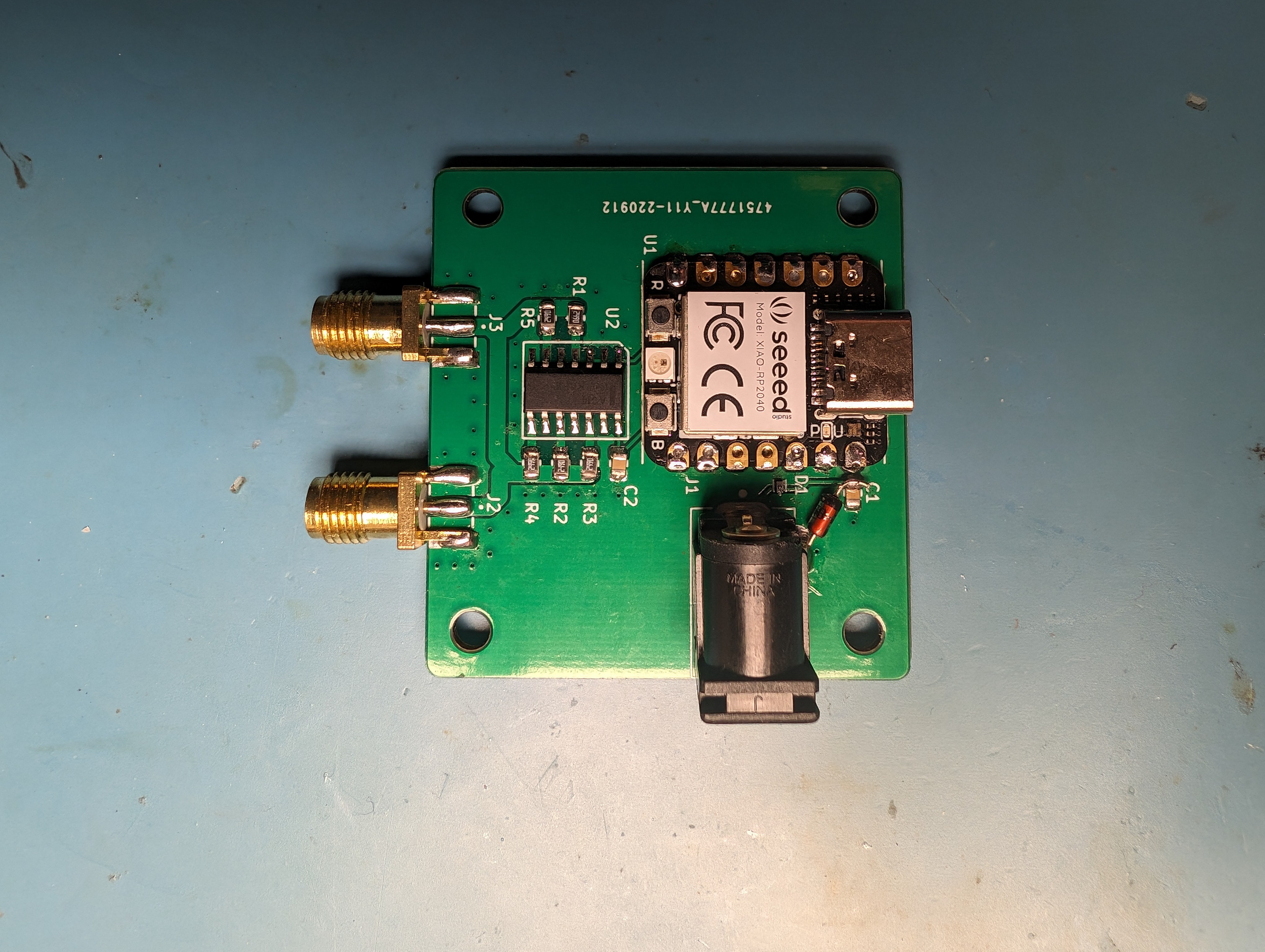
11/19/2023 at 01:18 • 0 commentsIn this revision of the PCB, I'm using a Seed XIAO RP2040, which is based on the RP2040. It's supported by CircuitPython which offers lots of useful libraries, but not one for the TDC chip I'm using. Generally I would say CircuitPython is pretty good for development, but does seem to have some stability issues when run for long periods of time. However, just dropping the code on a USB drive is pretty nice.
We are using the Time of Flight chip TDC7200 to measure the time between when we send a pulse and when we see the final reflection from the other end of the line. So the general flow is to setup everything by configuring the TDC and clock generation chip (a Si5351). Then trigger a measurement and read the result back.
The TDC is accessed over SPI and data is read or written into registers. So all the configuration looks like writing values to address with various bits set that indicate how the chip should be configured.
def config_tdc():
    calibration_periods = 1 # 1 = 10 periods
    calibration_shift = 6
    avg_cycles = 0b111 # 128 cycles
    avg_cycles_shift = 3
    reg_value = (calibration_periods << calibration_shift) | (avg_cycles << avg_cycles_shift)
    write_register(CONFIG2_ADDR, reg_value)
Everything is set as the default except we can enable taking multiple measurements and averaging it together on the TDC before returning the result. This ends up being much faster than doing the equivalent number of single measurements and doing the averaging on the RP2040 because it takes more time to do all the SPI interactions then it takes to do another measurement.
Another thing we need to setup is receiving the signal from the TDC to send a pulse. There are many different ways to do this, but since we want to do this quickly to minimize the time between measurements, I used a simple PIO program to just wait for a signal and then send the pulse to the Schmitt trigger.
# This will trigger a pulse whenever the TDC requests it
trigger_pio = '''
.program trigger
    wait 1 pin 0    ; wait for trigger pin to be set
    set pins, 1     ; send pulse
    set pins, 0
    ; loop back to the beginning
'''
triggered_asm = adafruit_pioasm.assemble(trigger_pio)
sm = rp2pio.StateMachine(triggered_asm,
                        frequency=10000,
                        first_set_pin=start_pin,
                        first_in_pin=trigger_pin)
The reason I didn't just set the output of the TDC directly to the Schmitt Trigger is that there is a minimum delay between the TDC requesting a start pulse and the pulse actually happening. The easiest way to add a delay is to have the RP2040 do it and then it can be adjustable too. Turns out that the no extra delay was needed.
So now we can actually do a measurement:
def do_measurement():
    "Time of flight in nanoseconds"
    start_measure = 0b1 # start measurement mode 1
    write_register(CONFIG1_ADDR, start_measure)

    # Wait for a measurement to be ready
    while done.value:
        pass

    time1 = read_register(TIME1_ADDR, reg_size=3) & TIME_MASK
    cal1 = read_register(CAL1_ADDR, reg_size=3) & CAL_MASK
    cal2 = read_register(CAL2_ADDR, reg_size=3) & CAL_MASK

    tof = calc_tof_mode1(clock, time1, cal1, cal2)
    # print("TOF = %s" % (tof*10**9))
    return tof * 10**9
Setting the start measure bit in the CONFIG1 register will cause the TDC to send the start signal back to the RP2040, which via the PIO program will send a pulse to the Schmitt trigger, which will then send the pulse, and the START pin of the TDC. Once that pulse reflection crosses the comparator level, a edge will be sent to STOP pin of the TDC.
This happens 128 times and when that is done, the done pin will be brought low, which indicates the RP2040 should read the result. Three values are read and then we can calculate the actual value
def calc_tof_mode1(clock, time, cal1, cal2):
    if time == 0 or cal1 == 0 or cal2 == 0:
        return -1
    freq = clock.clock_0.frequency
    period = 1/freq
    calCount = (cal2 - cal1)/9 # using default cal periods of 10
    if calCount == 0:
        return -1
    normLSB = period / calCount
    return time * normLSB
This is pulled right from the TDC datasheet.
I actually do even more averaging on the RP2040 since there is a fair amount of jitter in the measurements. It's just a simple sliding window based on the median of the measurements to better reject outliers.
samples = []
next_samp = 0
window_size = 50
samp_min = 8
samp_max = 50
def add_sample(new_samp):
    if new_samp > samp_max or new_samp < samp_min:
        return -1
    global next_samp
    if next_samp < len(samples):
        samples[next_samp] = new_samp
    else:
        samples.append(new_samp)
    next_samp = (next_samp + 1) % window_size

    return median(samples)

def median(lst):
    n = len(lst)
    s = sorted(lst)
    return (s[n//2-1]/2.0+s[n//2]/2.0, s[n//2])[n % 2] if n else None
Most of these outliers came from problems getting corrupted data over SPI.
SPI Issues
One of the weird issues I ran into was the SPI transfer would return garbage data sometimes. It took a while to track down what was happening, but it seemed to be related to the SPI clock speed. When I set the clock speed for the SPI bus:
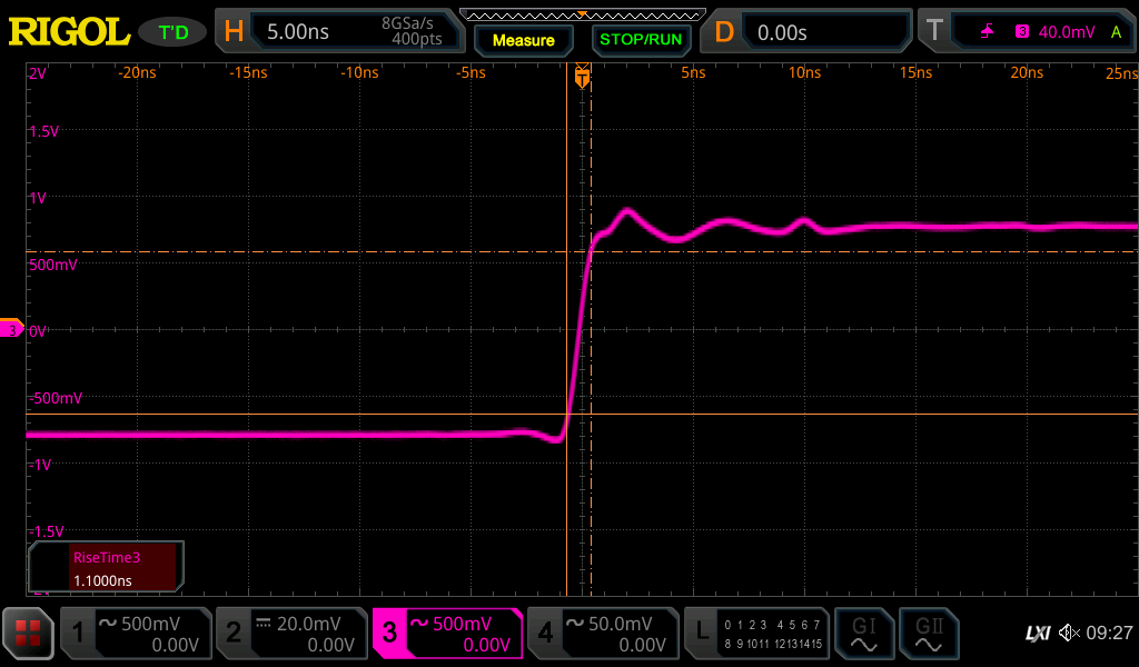
def open_spi():
    while not spi.try_lock():
        pass
    spi.configure(baudrate=2000000, phase=0, polarity=0)
The TDC could not operate at anywhere near it's advertised 20MHz. I originally suspected some kind of signal integrity issue, but after looking at the glitches I don't think so. Even when it "works" the MISO signal is very weak.
![]()
But sometimes it does manage to get to the normal voltage level
![]()
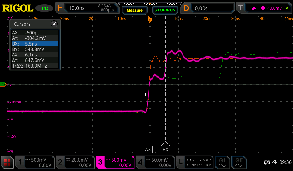
And if we increase the clock past 2MHz this gets even worse
![]()
At the point the RP no longer can actually read the data even if the scope can still decode it.
So we just limit to lower speeds than the datasheet says it should be able to handle. I'm still suspicious I'm doing something wrong, but I have no idea what it is and going slow seems to clear up the problem.
That's the general gist of the code. I'll include the full code for this revision in case it helps anyone else out.
Full code
import board import busio import adafruit_si5351 import adafruit_pioasm import rp2pio import board import busio import board import digitalio import pwmio enable = digitalio.DigitalInOut(board.D2) enable.direction = digitalio.Direction.OUTPUT enable.value = False start_pin = board.D0 trigger_pin = board.D1 out_pin = board.D6 pwm_out = pwmio.PWMOut(out_pin, frequency=5000000) done = digitalio.DigitalInOut(board.D3) done.direction = digitalio.Direction.INPUT done.pull = digitalio.Pull.UP cs = digitalio.DigitalInOut(board.D7) cs.direction = digitalio.Direction.OUTPUT cs.value = True spi = busio.SPI(board.SCK, MISO=board.MISO, MOSI=board.MOSI) def open_spi(): while not spi.try_lock(): pass spi.configure(baudrate=2000000, phase=0, polarity=0) CONFIG1_ADDR = 0 CONFIG2_ADDR = 1 INT_STATUS_ADDR = 2 INT_MASK_ADDR = 3 TIME1_ADDR = 0x10 CLOCK1_ADDR = 0x11 TIME2_ADDR = 0x12 CLOCK2_ADDR = 0x13 CAL1_ADDR = 0x1B CAL2_ADDR = 0x1C CAL_MASK = (1 << 23) - 1 TIME_MASK = (1 << 23) - 1 COUNT_MASK = (1 << 16) - 1 AUTO_INC_MASK = 0b10000000 RW_BIT = 0b01000000 REG_MASK = 0b0011111 def read_register(reg_addr, reg_size=1): result = bytearray(reg_size + 1) control = reg_addr & REG_MASK open_spi() try: cs.value = False spi.write_readinto(out_buffer=bytes([control] + [0] * reg_size), in_buffer=result) finally: cs.value = True spi.unlock() return int.from_bytes(result[1:], 'big', False) def write_register(reg_addr, data): control_data = reg_addr & REG_MASK control_data |= RW_BIT open_spi() try: cs.value = False spi.write(bytes([control_data, data])) finally: cs.value = True spi.unlock() return def config_si5351(): i2c = busio.I2C(board.SCL, board.SDA) si = adafruit_si5351.SI5351(i2c) si.pll_a.configure_integer(30) si.clock_0.configure_integer(si.pll_a, 50) si.outputs_enabled = True print('Clock 0: {0:0.3f} MHz'.format(si.clock_0.frequency/1000000)) return si clock = config_si5351() def calc_tof_mode2(clock, time1, time2, count, cal1, cal2): freq = clock.clock_0.frequency period = 1/freq calCount = cal2 - cal1 # using default cal periods of 2 normLSB = period / calCount TOF = normLSB * (time1 - time2) + count * period return TOF def calc_tof_mode1(clock, time, cal1, cal2): if time == 0 or cal1 == 0 or cal2 == 0: return -1 freq = clock.clock_0.frequency period = 1/freq calCount = (cal2 - cal1)/9 # using default cal periods of 10 if calCount == 0: return -1 normLSB = period / calCount return time * normLSB samples = [] next_samp = 0 window_size = 50 samp_min = 8 samp_max = 50 def add_sample(new_samp): if new_samp > samp_max or new_samp < samp_min: return -1 global next_samp if next_samp < len(samples): samples[next_samp] = new_samp else: samples.append(new_samp) next_samp = (next_samp + 1) % window_size return median(samples) def median(lst): n = len(lst) s = sorted(lst) return (s[n//2-1]/2.0+s[n//2]/2.0, s[n//2])[n % 2] if n else None # This will trigger a pulse whenever the TDC requests it trigger_pio = ''' .program trigger wait 1 pin 0 ; wait for trigger pin to be set set pins, 1 ; send pulse set pins, 0 ; loop back to the beginning ''' triggered_asm = adafruit_pioasm.assemble(trigger_pio) sm = rp2pio.StateMachine(triggered_asm, frequency=10000, first_set_pin=start_pin, first_in_pin=trigger_pin) def config_tdc(): calibration_periods = 1 # 1 = 10 periods calibration_shift = 6 avg_cycles = 0b111 # 128 cycles avg_cycles_shift = 3 reg_value = (calibration_periods << calibration_shift) | (avg_cycles << avg_cycles_shift) write_register(CONFIG2_ADDR, reg_value) def do_measurement(): "Time of flight in nanoseconds" # config_reg = read_register(CONFIG2_ADDR) # print("config2 = " + hex(config_reg)) # print("trigger: %s" % trigger.value) # start_measure = 0b11 # start measurement mode 2 start_measure = 0b1 # start measurement mode 1 write_register(CONFIG1_ADDR, start_measure) # config_reg = read_register(CONFIG1_ADDR) # print(hex(config_reg)) # status_reg = read_register(INT_STATUS_ADDR) # print(hex(status_reg)) # stop.value = True # stop.value = False # status_reg = read_register(INT_STATUS_ADDR) # print(hex(status_reg)) # config_reg = read_register(CONFIG1_ADDR) # print(hex(config_reg)) # cal1 = read_register(CAL1_ADDR, reg_size=3) # print(hex(cal1)) # cal2 = read_register(CAL2_ADDR, reg_size=3) # print(hex(cal2)) # if status & 1: # Wait for a measurement to be ready while done.value: pass # print("+", end="") # print("") # status = read_register(INT_STATUS_ADDR) # print("STATUS = %s" % hex(status)) # while not (status & 0b10000): # status = read_register(INT_STATUS_ADDR) # print("STATUS = %s" % hex(status)) time1 = read_register(TIME1_ADDR, reg_size=3) & TIME_MASK # print("TIME1 = %s " % hex(time1)) # time2 = read_register(TIME2_ADDR, reg_size=3) & TIME_MASK # print("TIME2 = %s" % hex(time2)) # count = read_register(CLOCK1_ADDR, reg_size=3) & COUNT_MASK # print("CLOCK1 = %s" % hex(count)) cal1 = read_register(CAL1_ADDR, reg_size=3) & CAL_MASK # print("CAL1 = %s" % hex(cal1)) cal2 = read_register(CAL2_ADDR, reg_size=3) & CAL_MASK # print("CAL2 = %s" % hex(cal2)) tof = calc_tof_mode1(clock, time1, cal1, cal2) # print("TOF = %s" % (tof*10**9)) return tof * 10**9 def main(): enable.value = True config_tdc() counter = 0 while True: avg = add_sample(do_measurement()) if avg == -1: print("-", end="") continue counter = (counter + 1) % window_size if counter == 0: print("\nTOF = %s" % (avg)) set_output(avg) else: print(".", end="") if __name__ == "__main__": main() -
Time of Flight Sensor
11/10/2023 at 18:19 • 0 commentsThe TDC7200 Time-to-Digital Converter chip came to my attention and despite it not exactly intended for this application, the basic functionality seems to be exactly what I need. It's intended to be used in something like a LIDAR system, where it measures the time between the outgoing pulse and the reflection. But the measurement resolution of 55ps with a standard deviation of 35ps should be more than enough my application.
So what I need to do is create a start and stop signal to feed into this chip and then read out the time of flight. The start pulse is easy, since I'm already generating that to feed into the Schmitt trigger to create the pulse, but the only twist is that the TDC requests the pulse instead of it just happening whenever. So, I wait for that with the RP2040 and then send out the start pulse.
Where I want to stop measuring is at the final reflection from the end of the PCB antenna. Since the TDC doesn't work off of voltage trigger level like an oscilloscope, I used a voltage divider to set the trigger level and a comparator to make a single step after that threshold is crossed.
I picked a very fast comparator, but in theory this actually isn't required since the absolute time between the start and stop pulse isn't important since we are just comparing relative readings, not the absolute value. So a cheaper chip is certainly possible as long as the rise time is less than 1ns and the delay is fixed.
The TDC also needs a clock, which I generated using Si5351 which gives me the ability to try out various frequencies, but in the end I just used the datasheet recommended frequency.
The board in action:
![]()
The SMA connector goes to the PCB antenna just sitting on the desk. I made a measurement that I saved to a ref (thin traces):
![]()
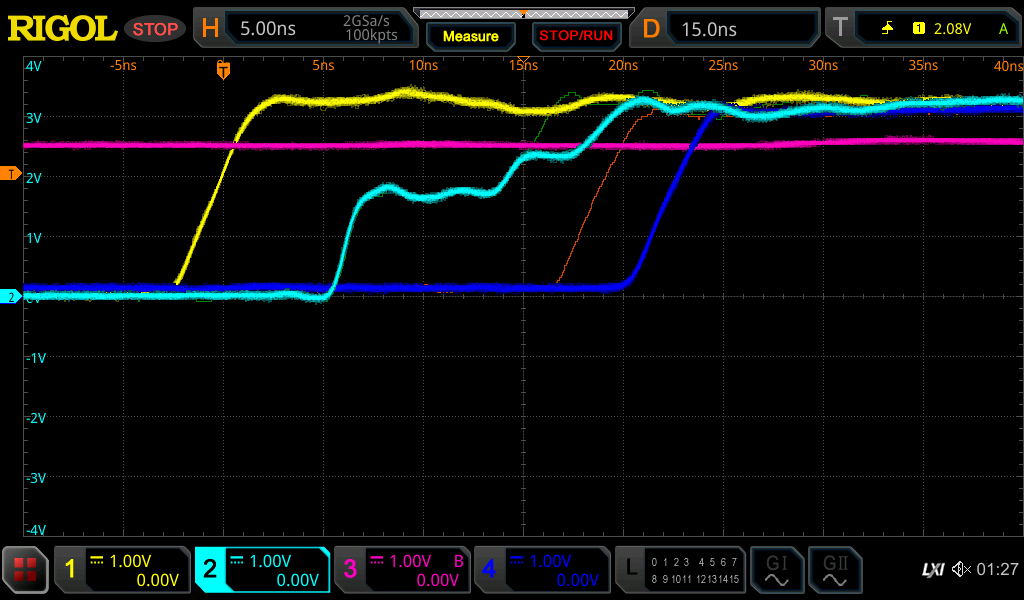
The yellow trace is the start pulse that then causes the light blue pulse to go to the antenna. The dark blue line is the comparator output and the magenta line is the trigger level. The light green thin ref line is the pulse with the antenna on the desk, so there is no extra step from the change in medium as the pulse goes down the trace. The comparator output with the antenna at that point is the orange ref line. I then covered the end of the antenna with my hand, causing a new step in the pulse trace from my hand right where the trigger level trace intersects the trace. This causes the comparator output to shift significantly. The difference between the orange ref trace and the blue trace is the result of my hand being on the antenna trace or not.
You can see the delay between the trigger level being crossed and the comparator output is about 5ns, but that is acceptable for this application.
In the end the only two traces that are measured by the TDC are the yellow and dark blue traces for the start and stop pulses. They are both clean edges for the TDC, unlike the mess that is the raw pulse trace.
Here's the reading from the TDC:
TOF = 19.5382
.........
TOF = 19.554
.........
TOF = 19.6037
.........
TOF = 19.6216
.........
TOF = 21.7848        <-- Hand placed on trace
.........
TOF = 22.386
.........
TOF = 22.6032
.........
TOF = 22.7481
.........
TOF = 22.8489
I'm reading the TDC reading via a serial console on the XIAO RP2040 and we can clearly see the jump in time of flight. The change is roughly what we see in the o-scope trace too (they aren't from the same moment, so they don't line up exactly).
Next time I'll go over the code needed for this.
-
EDN TDR Sensor
10/30/2023 at 02:34 • 1 commentAt this point we have something that at least proves out the concept of using TDR to measure soil moisture, but requires an oscilloscope to actually measure. To make this project work, I'll need to make a self contained way to measure that timing difference and it also can't cost much. So I want to avoid any ADC based based designs and instead focus on comparator and timing based designs.
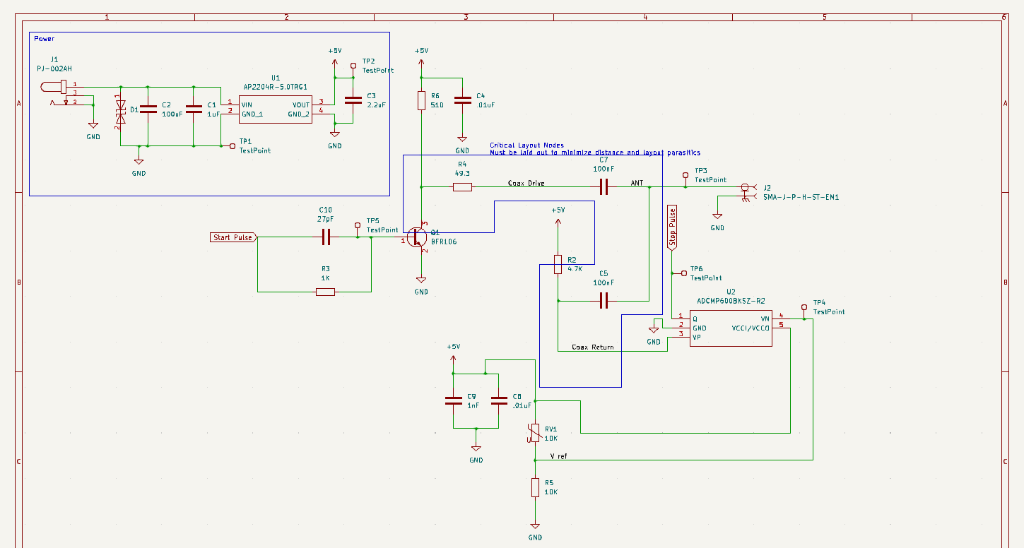
The first design I attempted to replicate was from an EDN article. There are some low res partial schematics in the article that I recreated:
![]()
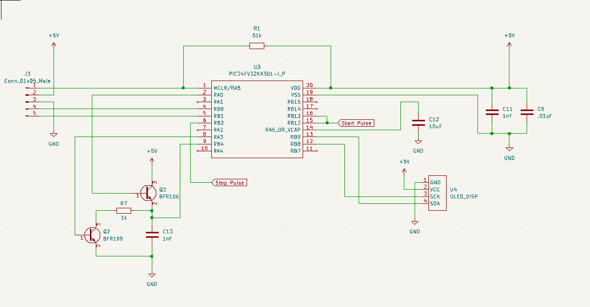
And also the PIC24F based digital section:
![]()
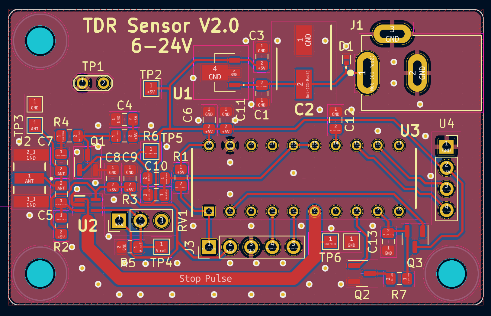
Which resulted in the following layout:
![]()
![]()
If you look closely, you may notice some unpopulated parts. I didn't take a picture until after I had already harvested a few components for the next version. There was a next version because this design ended up not having the resolution I needed to detect the differences between moist soil and slightly less moist soil. In the end it could measure a delay change of about 500ps which wasn't enough to reliably detect the moisture difference over a day.
So even if it didn't work out, I learned a few things while working with the PIC microcontroller and the CTMU. As mentioned in the article, the PIC has a current source it can start and stop charging a capacitor with. It then can measure the voltage on that cap to determine how much time has passed. Even with the current source set to the highest setting and using just the internal capacitance, the charge was too small to get an accurate reading. Also, the documentation on how to set the flags to get the right charge range where incorrect and had to be determined experientially.
The code is pretty simple and mostly configuration, so I'm including it here for completeness.
#define RANGE_5_50uA 1 // 5.50uA
void CtmuTimeConfig(unsigned int range, signed int trim)
{
    // Step 1 Configure the CTMU
    CTMUCON1 = 0x0000; // Disable CTMU
    CTMUCON1bits.TGEN = 0; // Disable Time Generation mode
    CTMUCON1bits.EDGEN = 1; // Edges are enabled
    CTMUCON1bits.EDGSEQEN = 1; // Edge sequence enable
    CTMUICONbits.ITRIM = trim; // Set trim
    CTMUCON1bits.CTTRIG = 1; // Trigger output enabled
    CTMUICONbits.IRNG = (range & 3); // Set range
    // This line does not apply to all devices
    //CTMUCON2bits.IRNGH = (range>>2); // set high bit of range

    CTMUCON2bits.EDG1MOD = 1; // Edge mode
    CTMUCON2bits.EDG1POL = 1; // 1 - rising edge 0 - falling edge
    CTMUCON2bits.EDG1SEL = 2; // 8 = CTED13 Pin 6 || 2 = CTED2 pin 15
    CTMUCON2bits.EDG2POL = 0; // 1 - rising edge 0 - falling edge
    CTMUCON2bits.EDG2MOD = 1; // Edge mode
    CTMUCON2bits.EDG2SEL = 8; // 8 = CTED13 Pin 6
//    CTMUCON2bits.IRSTEN = 1; // enable reset by external trigger
//    CTMUCON2bits.DSCHS = 4; // ADC end of conversion

    // Step 2 Configure the port Ports
    TRISBbits.TRISB12 = 1; // Configure RB12 as a input CTED2
    ANSBbits.ANSB12 = 0; // disable analog on RB12

    TRISBbits.TRISB2 = 1; // Configure RB2 as a input CTED13
    ANSBbits.ANSB2 = 0; // disable analog on RB2

    TRISAbits.TRISA0 = 1; // Configure RA0 as a input
    ANSAbits.ANSA0 = 1; // Configure AN0/RA0 as analog
    AD1CHSbits.CH0SA = 0 ; // Select AN0

    // Configure the cap drain output pin
    TRISAbits.TRISA3 = 0; // RA3 as output
    PORTAbits.RA3 = 0; // Set output low

    // Step 3 configure the ADC
    AD1CON1 = 0x0000; // Turn off ADC
    AD1CON1bits.SSRC = 0; // 4 - CTMU is the conversion trigger source 0 - manual
    AD1CON2 = 0x0000; // VR+ = AVDD, V- = AVSS, Don't scan,
    AD1CON3 = 0x0000; // ADC uses system clock
//    AD1CON3bits.ADCS = 8; // conversion clock = 1xTcy
    AD1CON5 = 0x0000; // Auto-Scan disabled
    AD1CON1bits.ADON = 1; // Enable ADC
    AD1CON1bits.ASAM = 1; // Auto-sample

    // Clear CTMU Interrupt
    IFS4bits.CTMUIF = 0;

    // Step 4 - 6 Enable the current source and stop manual discharge
    CTMUCON2 &= ~0x0300; // clear the edge status bits
    CTMUCON1bits.CTMUEN = 1; // Enable the CTMU
    CTMUCON1bits.IDISSEN = 1; // begin manual discharge of cap
    PORTAbits.RA3 = 1; // Drain the external cap
    __delay_ms(10); // Wait for the drain to complete
    CTMUCON1bits.IDISSEN = 0; // stop discharge of cap
    PORTAbits.RA3 = 0;
}

static void config_ADC_ext_cap() {
    AD1CON1 = 0x0000; // Turn off ADC
    ANSA = 0; // Clear register select
    ANSB = 0;
    // Configure RB4/AN15 to read the voltage on external cap
    TRISBbits.TRISB4 = 1; // Configure RB4 as an input
    ANSBbits.ANSB15 = 1; // Configure AN15 as analog
    AD1CHSbits.CH0SA = 0b01111; // Pick AN15

    AD1CON1bits.ADON = 1; // Enable ADC
    AD1CON1bits.ASAM = 1; // Auto-sample
}

#define MAX_TRIGGER_CHECKS 100
/*
    Main application
 */
int main(void)
{
    char print_buf[128] = {0};
    // initialize the device
    SYSTEM_Initialize();

    SSD1306_Begin(SSD1306_SWITCHCAPVCC, SSD1306_I2C_ADDRESS);
    SSD1306_set_rotation(SSD1306_ROTATE_180);
//    SSD1306_Display();
//    __delay_ms(2000);
    SSD1306_ClearDisplay();
    SSD1306_DrawText(2, 7, "Hello, world!", 1);
    SSD1306_Display();

    // Configure the pulse output pin
    TRISBbits.TRISB13 = 0; // RB13 as output
    ANSBbits.ANSB13 = 0; // disable analog on RB13
    PORTBbits.RB13 = 0; // Set output low

    unsigned int result;
    CtmuTimeConfig(0, 0); // 550uA

    int count;
    int flip = 0;
    while(1)
    {
        count = 0;
        PORTBbits.RB13 = 1; // Trigger pulse
        PORTBbits.RB13 = 0; // Reset pulse
        // Wait for CTMU interrupt
        while(IFS4bits.CTMUIF == 0) {
            count++;
            // Bail if we fail to trigger
            if(count > MAX_TRIGGER_CHECKS) {
                CTMUCON2 &= ~0x0300; // clear the edge status bits
                goto main_loop_end;
            }
        }
        // Clear CTMU Interrupt
        IFS4bits.CTMUIF = 0;

        //config_ADC_ext_cap();
        // Make sure the interrupt is already cleared
        IFS0bits.AD1IF = 0;
        // Trigger ADC conversion
        AD1CON1bits.SAMP = 0;
        // Step 7: Wait for ADC interrupt
        while(IFS0bits.AD1IF == 0){}

        // Steps 8-11
        IFS0bits.AD1IF = 0; // clear the interrupt
        result = ADC1BUF0; // read ADC result

        CTMUCON1bits.IDISSEN = 1; // begin manual discharge of cap
        PORTAbits.RA3 = 1; // Drain the external cap
        __delay_ms(10); // Wait for the drain to complete
        CTMUCON1bits.IDISSEN = 0; // stop discharge of cap
        PORTAbits.RA3 = 0;

        CTMUCON2 &= ~0x0300; // clear the edge status bits

        // Write results to screen
        char format[] = "ADC: %d %s";
        int slen = sprintf(NULL, format, result, flip ? "." : " ");
        if(slen < sizeof(print_buf)-1) {
            sprintf(print_buf, format, result, flip ? "." : " ");
        } else {
            sprintf(print_buf, "Print too long");
        }
        SSD1306_ClearDisplay();
        SSD1306_DrawText(2, 7, print_buf, 1);
        SSD1306_Display();

main_loop_end:
        // Wait a bit
        __delay_ms(10);
        flip = !flip;
    }
    return 0;
}
I didn't write much in the way of documentation or screen shots of the experimental results since I was focused on getting it working, and since it didn't, I don't really feel like going back and setting it up again.
At this point it was back to the drawing board for the sensor side of the project, which we'll take a look at in the next log.
-
TDR Antenna
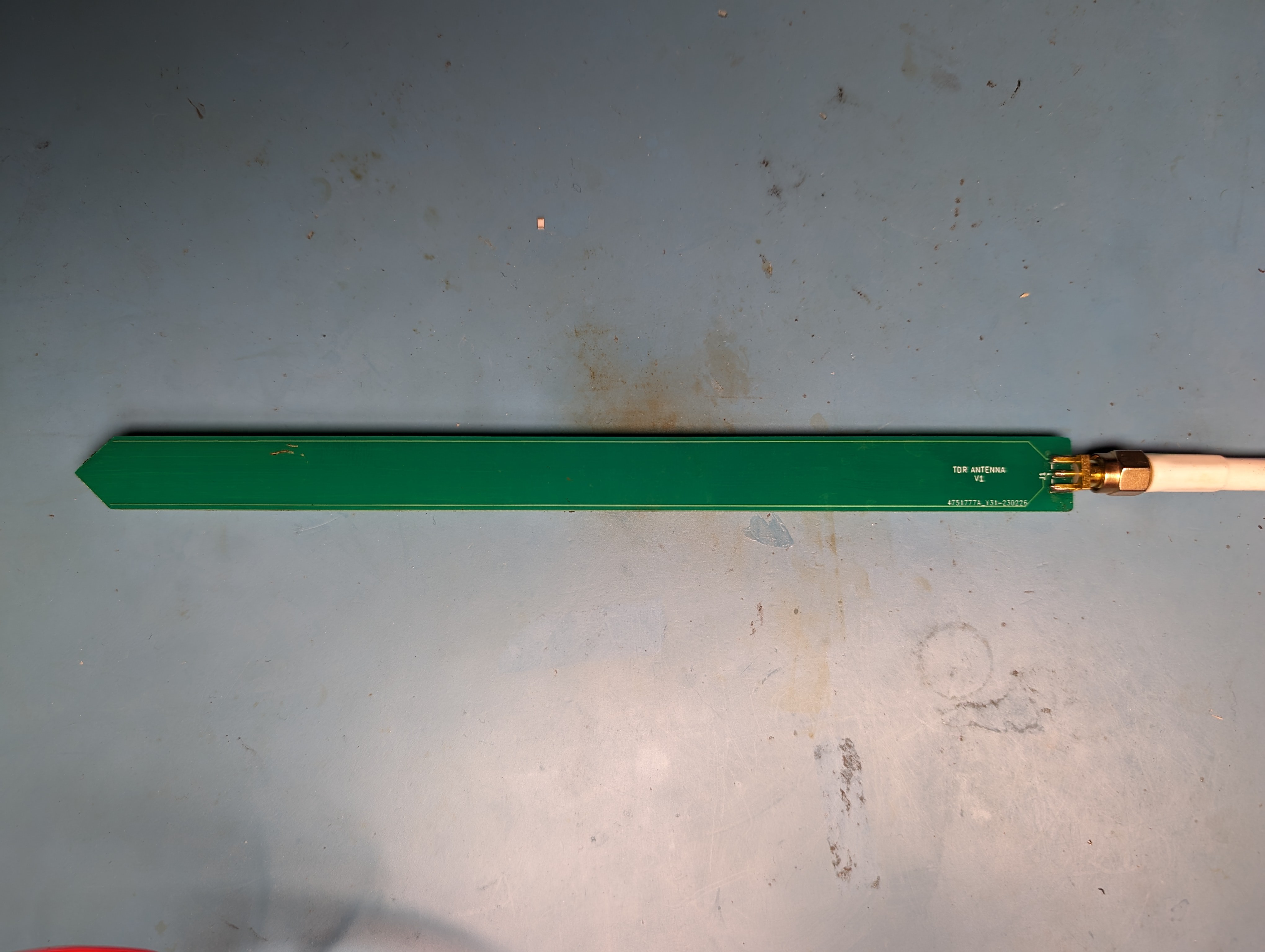
10/16/2023 at 03:17 • 0 commentsI have no idea what design parameters are needed to maximize the effect of whatever medium the TDR step has on the propagation speed. So I started with just two stainless steel 2mm rods in parallel with ground on one rod and the pulse on the other. This did work, but the connection between the rods and the copper clad PCB I had just cut two pads into with a knife was not great. I ended up making another PCB for this.
![]()
There is no ground plane based on the thought that I want as much of the EM field to go through the surrounding medium instead of there being a short path to ground. The impedance of this trace will be higher than 50ohms, so in theory that will cause some refections as it goes from the 50 ohm cable to the pcb, but we only care about the last reflection that goes all the way down the trace.
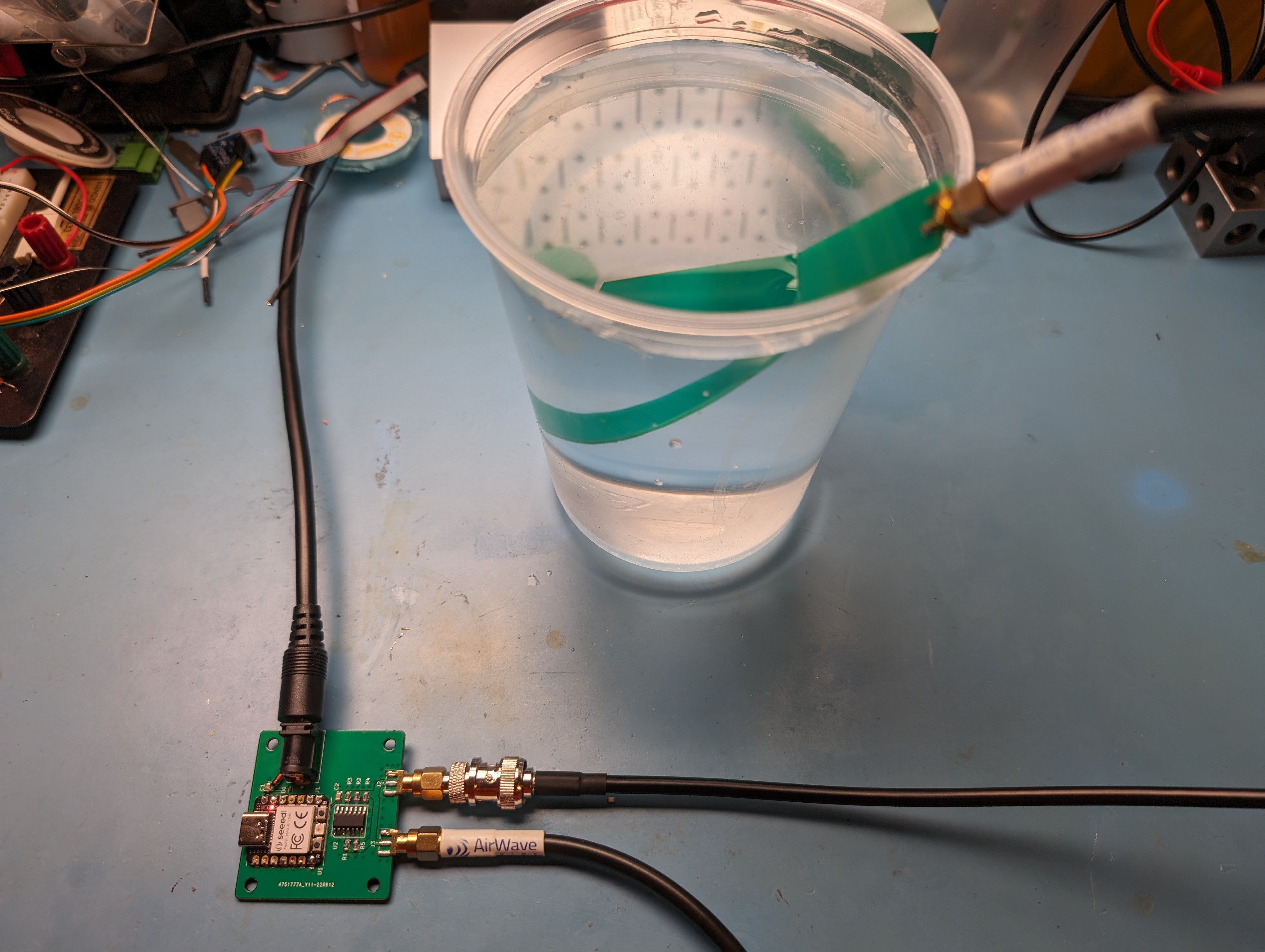
To test how well this works, we can measure the difference between air and fully immersed in water
![]()
Which looks like this on the scope:
![]()
The green trace is the antenna in open air and the magenta trace is fully immersed in water. Most of the length of the step is the same, but at the 9ns the reflection starts coming from the antenna. Each division is 10 nanoseconds, so the water reflection is about 5 ns slower than open air. This is about the maximin difference we can expect to be able to detect.
So, lets stick it into some soil and see what it looks like.
![]()
Here the difference between the two traces are when the soil is dry and freshly watered. The antenna was not inserted as deep into the pot as it was into the water, so we can see the change is nearer the top of the step. It is also smaller because the change in water content is not as large between the dry and moist soil. In this case it is 3ns right after watering.
The difference in timing is only a few nanoseconds at best. That's pretty small and I'd like to be able to differentiate between various levels of moisture content which will need sub-nanosecond resolution. The good news is that it is a relative measurement. My scope which can only measure a rise time of about 1ns can resolve differences much less than that.
The original TDR article on EDN has a design for measuring the difference in TDR pulses, so the plan is to build one and test if it has the resolution needed for this application.
-
Pulse Generator
10/15/2023 at 17:41 • 0 commentsThere's already quite a few of builds of cheap pulse/step generators online, so I just picked one to base my build on:
Even though something like a 555 timer could generate the start pulse to feed the Schmitt trigger, I ended up putting a XIAO RP2040 to just generate a pulse via PWM.
![]()
![]()
![]()
I put two edge launch SMA connectors so I could run one to whatever I was trying to test and one to my oscilloscope. The theory behind simple TDR measurements assumes that there's only one transmission line involved and adding the second one to the scope would cause it's own set of reflections into the high impedance scope termination. So I added a 50ohm termination at the scope, which I have to do with an external passthrough termination:
![]()
The 50 ohm termination will load the signal, which will cause the magnitude of the signal to be decreased compared to when the scope isn't connected, but that doesn't matter in this case since it will only be used with something attached to make the reading.
![]()
This pulse has a rise time of a little more than 1ns into 50 ohms, which is about the limit of the bandwidth of my 350MHz scope.
Attaching different lengths of coax shows that the basic TDR measurements work.
![]()
Which results in the following trace:
![]()
The orange ref trace is when nothing is connected. The active trace is with a 2ft coax attached. The green trace is with a much longer coax cable attached. The different length of coax cause a step from the delayed reflection off the other end of the cable. The length of that delay is proportional to the length of the cable. That same delay is what I'm aiming to measure to in soil.
Now I need to make something to probe soil and see the TDR measurements.
-
Initial Research
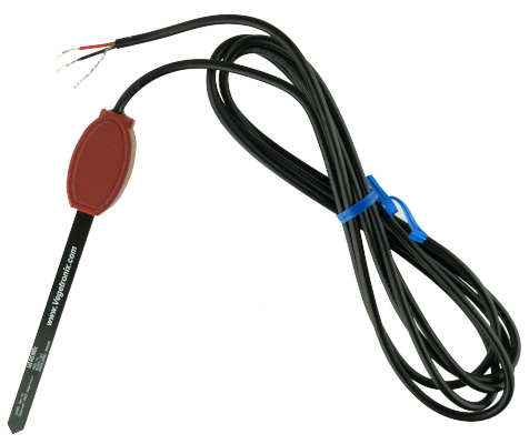
10/15/2023 at 04:35 • 0 commentsFirst step of any of these DIY projects is to check if I can just buy the solution. At first glance, the price jump between most capacitive sensors and low end TDR sensors is pretty big but some cheaper examples of TDR sensors exist at the $50 price point:
![]()
https://www.vegetronix.com/Products/VH400/
More than I'd like to spend on each plant I want to water, so there's actually a chance it makes sense to create my own solution that will be cheaper if I need to make several.
Alright, so how does that actually work? Well, turns out there a pretty good background article on that too:
https://www.edn.com/use-time-domain-reflectometry-tdr-for-low-cost-liquid-level-measurement-part-i/
https://www.edn.com/use-time-domain-reflectometry-tdr-for-low-cost-liquid-level-measurement-part-ii/
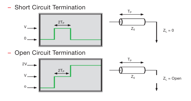
The TLDR version is that the speed that a voltage step moves down a transmission line is related to the medium the electric fields pass thru. In PCBs this is the typically FR4 fiberglass that makes up the board itself, not the copper of the traces itself. This is true for cables and anything else too. Also, an open or short circuit will cause that voltage step to be reflected back to the sender, it is possible to measure the time it reach the end of the transmission line and come back from the sending side by looking at the final voltage step.
So the basic concept is that by measuring that time, one can learn something about the medium the step is traveling thru. For example, by dunking the line in water will cause the time to increase when compared to the time when the line is in open air.
![]()
More subtle differences, like that between dry soil and damp soil are also possible and that seems to be the working principle of these TDR soil moisture sensors.
But how subtle is that difference? I figured it would make sense to test this out first, so I will build a pulse generator I can use with my oscilloscope as a proof of concept.
TDR Soil Moisture Sensor
I just want to water my plant, but cheap moisture sensors are pretty bad. Here I attempt to make a better one.