 Rene
Rene-
Current Goal: new PCB order before Oct 2018
09/25/2018 at 07:37 • 0 commentsThings have been a bit crazy at work for the past year, leaving me with limited time to spend on this project. I'm on leave for this week, and aim to send off the revised PCB order by 30 September 2018. This includes:
- Design PCB for EastRising 3.4" LCD module
- Design PCB for the Navigation module
- Revise PCB for the Rotax 582 Engine Interface module
- Revise PCB for the Monochrome LCD modules
-
Design Notes for Shielding and EMC issues
09/25/2018 at 07:02 • 1 commentThe current avionic modules still cause interference on my VHF air-band radio. Whenever the power switch for the avionics is turned on, the radio intermittently shows the Rx light and plays channel noise. Turning the squelch all the way up reduces the issue to some extent. Unplugging the antenna on the radio stops the issue, leaving me to believe that I am dealing with radiated emissions from the avionics, rather than conducted emissions through the power supply.
Below are some design notes for the next hardware revision to mitigate the EMC issues:
- run the micro-controller at 80 MHz rather than 120 MHz (move the I/O and transistor switching noise further away from the air-band VHF frequencies)
- PCB ground fill on both sides (traces become more like coplanar waveguides rather than radiating antenna elements)
- PCB solder pads for an EMC cage (brass sheet bent into a box)
- use in-line termination resistors for signals between integrated circuits on the same board
- use low noise switching power supply modules
The whip antenna position (in close proximity to the instrument pod) and limited ground plane (using the goose neck on the aluminium frame) are not ideal on my microlight trike. The aluminum frame structure and many stainless steel support wires make the antenna mounting challenging and distort the radiation pattern. I have not measured the VSWR, but expect quite a bad impedance match and significant reflections. If the next hardware revisions still cause interference issues, I will consider mounting a V or dipole antenna to the king post or the back of the keel.
-
Sunlight Readable LCD Selection
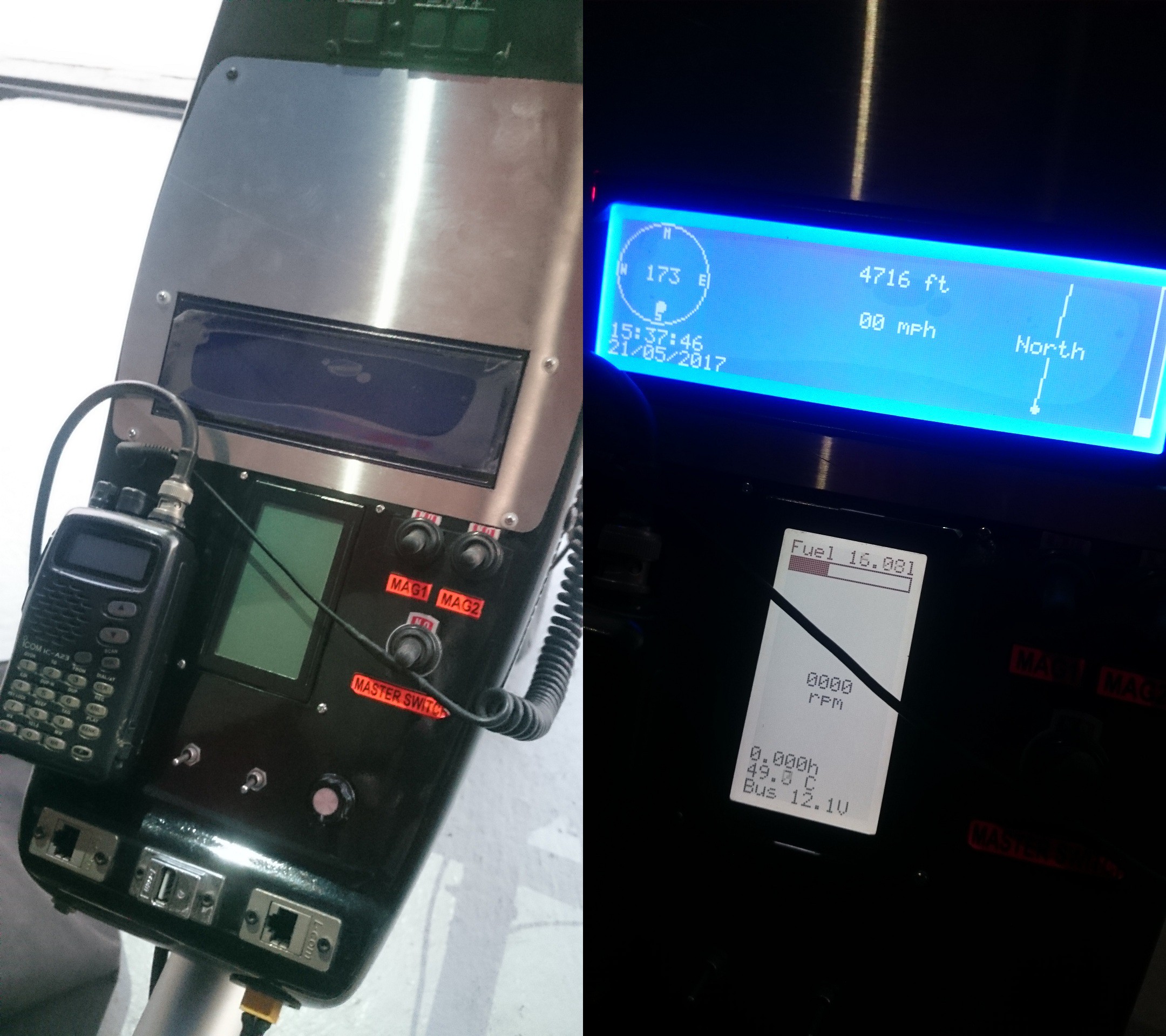
07/09/2017 at 12:37 • 0 commentsI initially thought the 5.8" white-on-blue LCD module would be readable in sunlight, but having flown with it a few times now, the white pixels mostly vanish under direct sunlight (even with the blue back-light set to maximum brightness). For sunlight readable screens:
- Any monochrome LCD should be of FSTN Positive type, preferably with black pixels on a white/grey background.
- Any color TFT LCD screen needs to have an ultra-bright back-light with an absolute minimum brightness of 700 nits (1 nit is equivalent to 1 cd/m2).
For sunlight readable color TFT screens, the transflective variants (which transmit light when the back-light is turned on and otherwise reflect light) are extremely expensive and difficult to procure. TFT modules with ultra-bright back-lights are easier to procure but typically cost a few hundred dollars. After multiple days of googling, browsing catalogs and comparing screens, I've selected the following options, which should suit most cockpits and budgets:
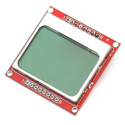
1. Nokia 5110 LCD Module
1.4 inch (29 x 19 mm active area) 84x48 pixel monochrome, (less than $2 on AliExpress).

These modules use the PCD8544 controller with a serial interface to the microcontroller. Their small size makes them ideal to fill a standard 2.25" instrument panel hole. One could have multiple of these in the cockpit, each with enough space to show a graphical widget, 1 to 2 large font parameters, or 6 to 7 small font parameters.
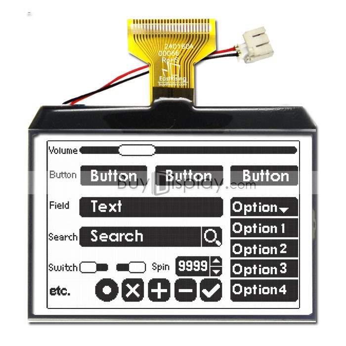
2. EastRising ERC240160FS-1 Module
3.4 inch (72 x 48 mm active area) 240x160 pixel monochrome, (around $11 from BuyDisplay).
The solderable FPC ribbon interface supports both 8-bit parallel as well as serial communication to the ST7586 controller. The screen size, pixel density and price make this module quite attractive for most use cases.
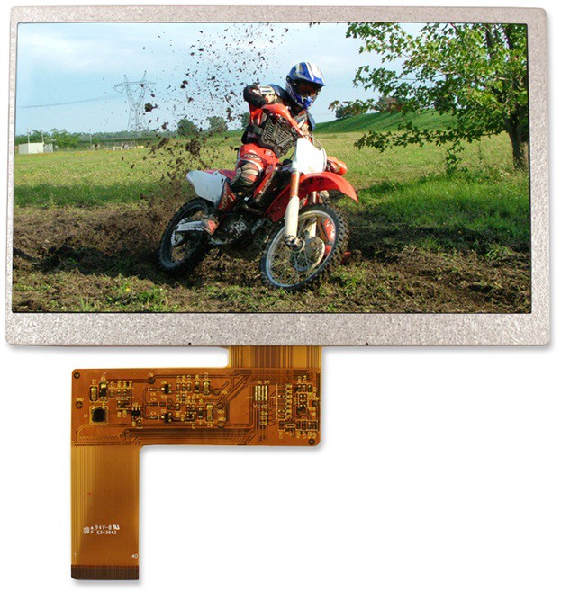
3. Newhaven NHD-7.0-800480EF-ASXN# Screen
7 inch (154 x 86 mm active area) 800x480 pixel color, 1000 cd/m2, (around $80 from Newhaven).
This is by far the cheapest sunlight readable TFT screen that I found in this size category. It uses a 24-bit parallel RGB interface, which is supported by most single board computers (e.g. the RaspPi Display Parallel Interface [DPI] as a multiplexed function on the GPIO pins). Alternatively an external controller can be used to drive it via HDMI. Touchscreen versions are also available, trading off a bit of brightness.
-
Lesson Learnt: Shielding
05/23/2017 at 19:42 • 0 commentsLast weekend I got the firmware to a state where it could be used in the aircraft and installed it all into the pod... Not very pretty, but it'll do for now.
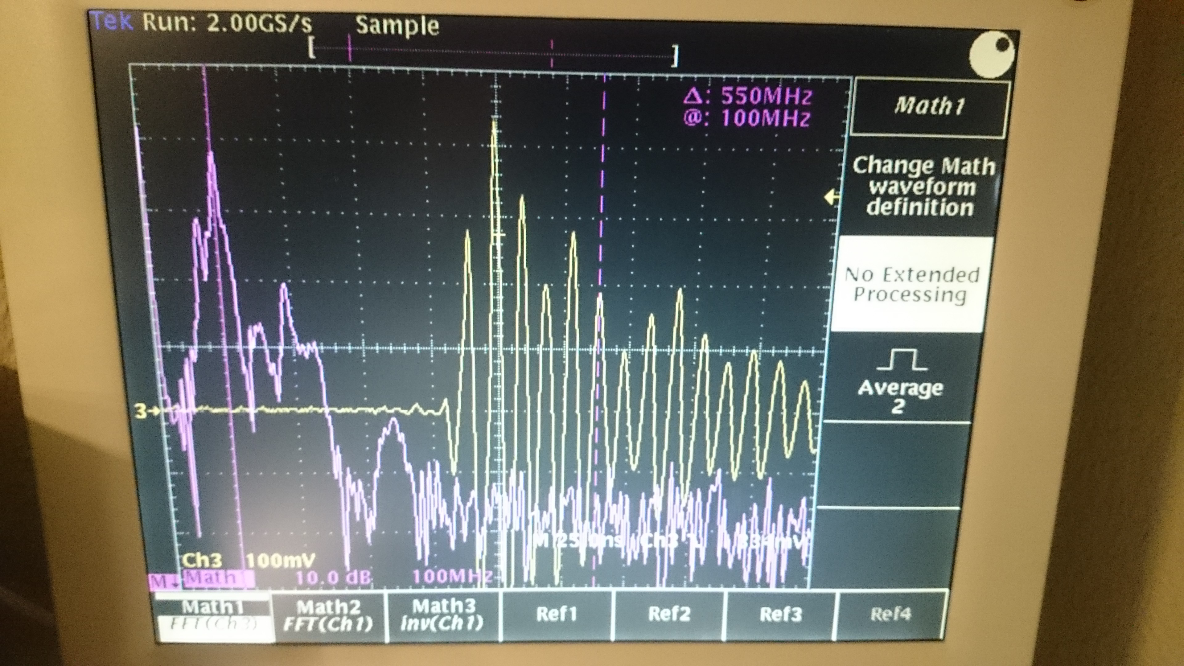
During my pre-flight checks I noticed that the radio was picking up interference (the SQL had to be set all the way up to suppress it); Upon closer inspection with the oscilloscope I noticed that the switched mode power supplies were ringing around 100 MHz during both the rising and falling edges... Additionally the Microchip PIC is set to run at 119.763 MHz. The capture below was taken with a floating probe around 5-10cm away from the SMPS.
Re-wiring the electronics with shielded cables (and connecting only ONE side of the shield to ground) fixed the issue. It's clear that each of the modules as well as all interface cables should be properly shielded to suppress their emissions, and shield them from the VHF radio and transponder RF!
-
Other CAN-bus Aviation Protocols
04/22/2017 at 12:29 • 1 commentThis section tracks and compares various aviation-specific CAN-bus protocols. Being open source, support for these protocol can always be added at a later stage if required.
See also: Comparison by J Klüser, Comparison by A Brehmer.
MakerPlane CAN-FIX
Flight Information eXchange Protocol over CAN. Useful document for reference: min / max ranges of parameters etc. I find it too restrictive in some aspects, whereas other aspects have not been addressed at all.
ARINC 825
Very promising; used by Airbus and Boeing. Unfortunately the standard is behind a paywall. There is insufficient open information for implementation...
CANopen
Used for space applications (ESA programs)
CANaerospace
Standardized by the US National Air and Space Administration (NASA) as "AGATE Airplane Avionics Data Bus". Used in several aircraft; primary use in engineering simulators
-
Other Open Source Avionics
04/22/2017 at 11:56 • 0 commentsThis section tracks other open source avionics projects, for the purpose of collaboration and design reuse. Please let me know if you know of any other initiatives.
MakerPlane
After being idle for a few years, the MakerPlane avionics section gained some momentum again between early and middle 2016. Their Python (PyQt) EFIS GUI looks quite good.
http://www.makerplane.org/forum/viewforum.php?f=19
https://github.com/makerplane/pyEfis (switch to the 'develop' branch)
https://github.com/makerplane/FIX-Gateway
https://github.com/jmg22/pyEfis
Stratux
Their FlightBox is a ADS-B / GPS / AHRS data to Tablet / Phone interface. It consists of a Raspberry Pi with USB Dongles: 2x SDR, WiFi. AHRS expansion port.
https://github.com/cyoung/stratux
https://www.openflightsolutions.com/
Compatible Apps: WingX Pro, iFly GPS, FlyQ EFB and FF.
Marian Keller - AHRS platform for gliders
Bluetooth module for smart devices.
https://hackaday.io/project/20456-ahrs-platform-for-gliders
Experimental Avionics - Arduino EFIS
Looks very promising. Second prototype already. Updated end of 2016.
http://experimentalavionics.com/efis-19264/
Marc Robitaille - Arduino EFIS
Altimeter, Airspeed, Horizon, Slip, Vertical speed
YouTube Link (with dropbox link in description)
FlightGear Flight Simulator
Open source simulator (similar to Microsoft Flight Simulator). Might be useful to use some of their front end / GUI.
Others
Forum to discuss. Maintainer longer has aircraft. No content on website;
http://www.opensourceavionics.com/wp/
Arduino Altimeter
http://www.diyavionics.com/projects/arduino/altimeter
Activity between 2003 and 2005. OpenGL + Qt. Download able ‘efis.0.1.1.tar.gz’
https://sourceforge.net/projects/avionics/
Density Altitude Gauge; no source code, never completed?
https://hackaday.io/project/5072-density-altitude-gauge
Source code for MGL Avionics - Ultra HXL was released, but just dead links now.
http://www.vansairforce.com/community/showthread.php?t=76777
-
System Bus Decision
04/22/2017 at 10:21 • 0 commentsThe entire design is built around a shared bus, into which multiple modules, interfaces and screens are plugged in. With various sensors asynchronously producing data, a one-to-many bus that supports message broadcasting is required. This leaves us with some options...
- Ethernet
- I2C bus (in multi-master mode)
- Wireless transceivers
- Custom bus with collision avoidance rules
- CAN bus
Ethernet tends to be a bit too expensive for simple modules, and requires a bulky Ethernet switch. I2C is susceptible to electrically noisy environments, requires a master node to poll slave nodes, and the data rates are quite low. Wireless transceivers are usually not full-duplex and become unreliable when there are too many transmitters and packet collisions occur.
Initially I ran UART over the CAN physical layer (saving some cost and overcoming the maximum 8-byte CAN payload limit), and added some arbitration rules to the protocol. This required some assembly optimisation to check for collisions after each bit transmission, but worked quite well. With the number of sensors increasing, I started to feel a bit uneasy about the reliability of this implementation though.
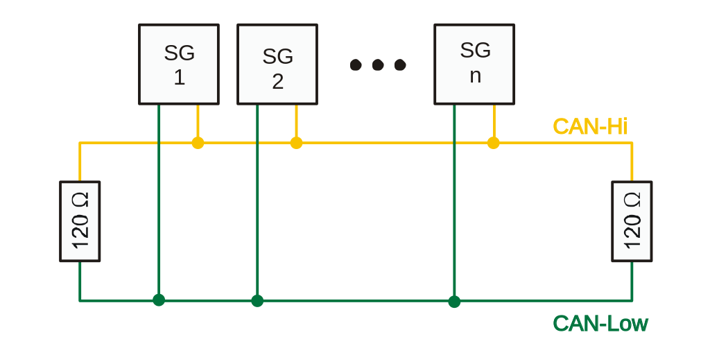
Hence, the CAN bus was chosen. It is robust (differential pair), features automatic message arbitration (packet collisions are impossible), and is used widely in the aerospace and automotive industries. The can bus consists of a CAN_HI and a CAN_LO differential pair, which is terminated (HI and LO pins connected together with 120 Ohm resistors) on each end of the bus. When no node is driving the bus, the resistors pull the HI and LO lines together and the bus is a high-impedance "recessive state" (logical 1). During a "dominant state" (logical 0), one or more nodes drive the HI line towards +5V and the LO line towards 0V.
(Image from Wikipedia)
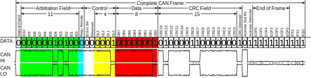
Messages are sent out on the bus with a unique CAN-ID, which identifies the message and also acts as a priority. After each bit is sent, the bus is checked for a potential collision by the CAN controller. When multiple nodes attempt to simultaneously transmit, the node with the lower CAN-ID (first dominant bit in the ID) continues transmitting, while the other node back's off and re-transmits at a later stage.
(Image from Wikipedia)
One disadvantage of the CAN-bus is the small message size: an 11 or 29-bit CAN ID, and 0-8 data bytes. Yes, a maximum payload length of 8 bytes!!! Luckily most sensor values that are broadcast periodically (and make up the majority of bus traffic) can be represented with a single precision floating point (4 bytes). -
Feature Wishlist
04/20/2017 at 12:53 • 0 commentsI find it useful to envision as many future requirements as I can think of. That way the architecture can be designed with future upgrades in mind, even if these features are never actually implemented.
- Support for multiple display sizes and types
- TFT LCD
- Character STN LCD modules
- Graphic STN LCD modules
- eInk displays
- OLED screens
- Analog dial gauges (via PWM)
- LED displays (bar graphs, 7 segment, matrix)
- Support for Android / iOS devices as additional graphical user interfaces and for internet access
- Smartphones
- Tablets
- Smartwatches
- Synthetic Vision System (SVS)
- Moving Map View
- Airports / landing strips
- Airspaces
- Current and predicted Weather
- Waypoints and path planning
- Other Airplanes in the area
- Via Automatic Dependent Surveillance - Broadcast (ADS-B)
- Via Low-Cost ISM-Band Transceiver (for friends in your group)
- Engine Monitoring (multiple engines)
- Revolution Counter (RPM)
- Hour Meter (Hobbs)
- Maintenance / service timer
- Exhaust Gas Temperatures (EGT)
- Cylinder Head Temperatures (CHT)
- Coolant Water Temperature (H20)
- Oil Temperature
- Oil Pressure
- Manifold Pressure
- Alternator Voltage
- Alternator Current
- Fuel Management (multiple fuel systems)
- Fuel Level
- Fuel Pressure
- Fuel Flow (Instantaneous, Average, Accumulated)
- Fuel Range / Endurance
- Fuel Pump Control
- Navigation Instruments
- Heading
- Magnetic Heading (compass)
- True Heading (GPS based)
- VHF Omni Directional Radio Range (VOR)
- Speed
- Air Speed (pitot tube)
- Ground Speed (GPS based)
- Vertical Speed Indicator (pressure differential)
- Vertical Speed Indicator (GPS altitude differential)
- Glide Ratio
- Altitude
- Barometric Altitude (user QNH setting)
- Flight Level (QNH=1013.2 hPa)
- True Altitude (GPS based)
- Radar Altimeter
- Height above runway (ultrasonic sensor)
- Attitude and Heading Reference System (AHRS)
- Artificial Horizon
- Inclinometer
- G-Force meter
- Angle Of Attack (AOA) Indicator
- Turn Coordinator
- Turn and Slip Indicator
- GPS Position Coordinates (multiple formats)
- Distance covered
- Flight Time
- Reporting point helper
- Distance and heading to nearest reporting point (e.g. 3 miles NE of XYZ) for radio position reports
- Waypoints management
- Route and waypoint editing
- Course Deviation Indicator (CDI)
- 3D Heading to next waypoint
- Vertical Distance to next waypoint
- Horizontal Distance to next waypoint
- Time to next waypoint
- Default waypoint: takeoff location
- Heading
- Flight Data Logging (black box)
- Visual and audible warnings (navigation, thresholds exceeded, etc)
- Interface with other Avionics
- Altitude encoder for Mode C Transponders
- Transponder Remote Control
- Intercom Remote Control
- Air Band Transceiver (Radio) Control
- Pilot Notes / Checklists / Frequencies
- Edit
- View
- Upload
- Download
- Aircraft Status and Control
- Battery Voltage
- Battery Current (charge / discharge)
- Flap position
- Landing gear
- Strobe light
- Headlight
- Heater control
- Heat Vest control
- Stopwatch / Countdown
- Density Altitude
- Ambient Air Temperature
- Date / Time (from GPS)
This list is by far not complete, but should give a good starting point for the detailed design.
- Support for multiple display sizes and types
-
Background
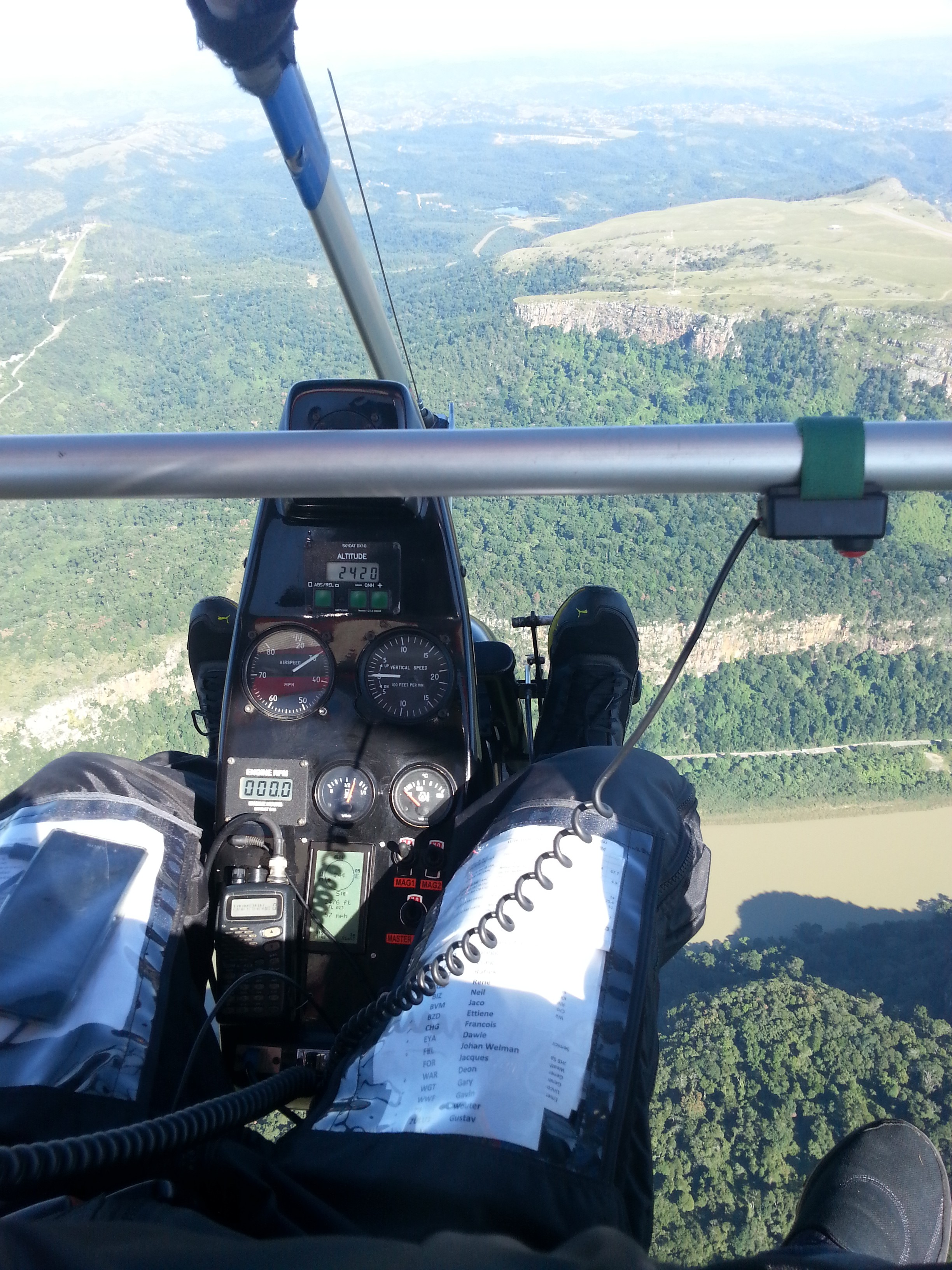
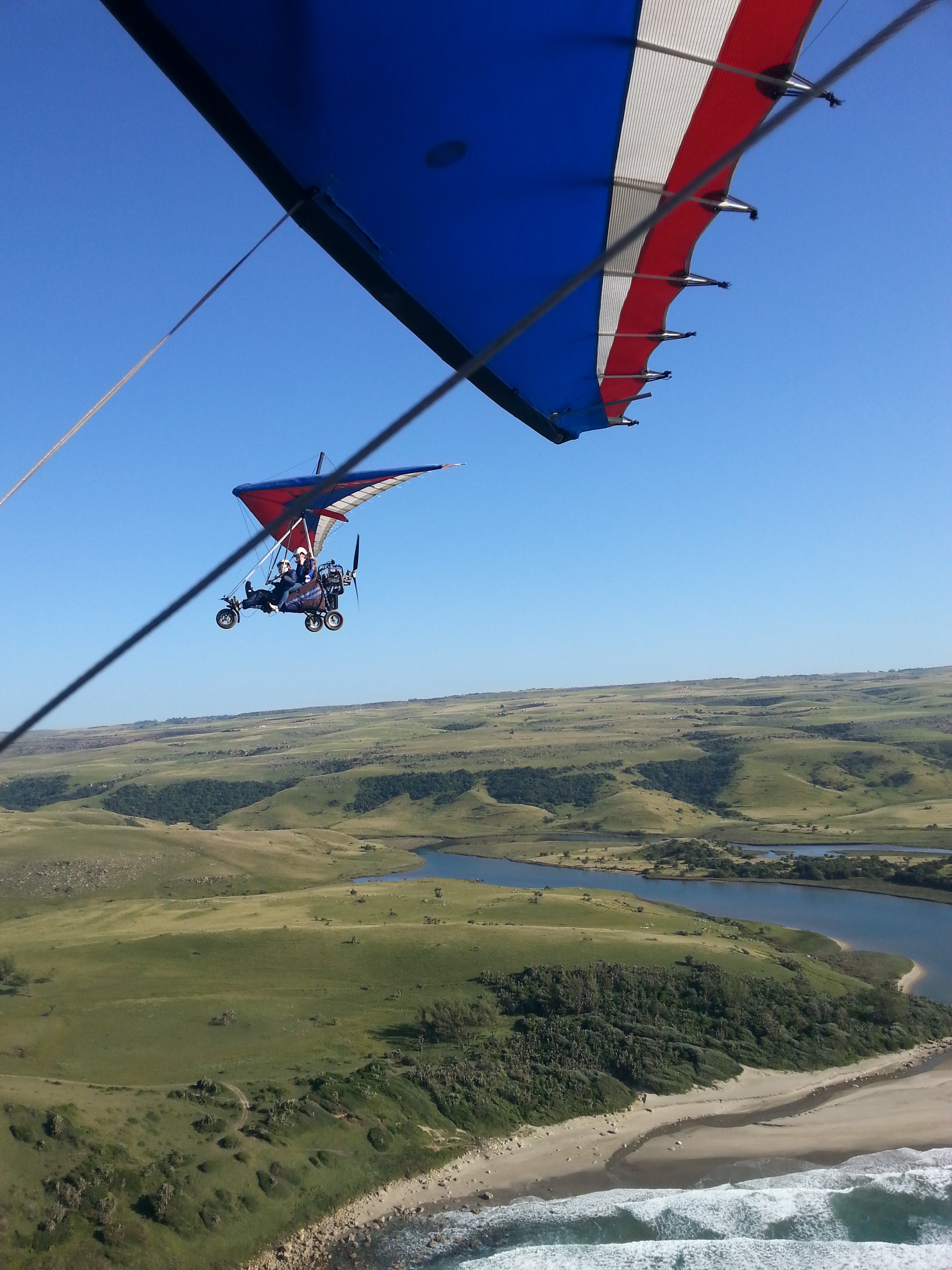
04/20/2017 at 12:49 • 0 commentsI have always dreamed of flying and was fortunate enough to be able to complete my recreational pilot license a few years ago. South Africa is an amazing country to explore by air, especially in an open cockpit of a Weight Shift Controlled (WSC) trike!
My wife took the picture below as we were flying along the Wild Coast. The pilot sits in front, with the passenger in the rear seat.
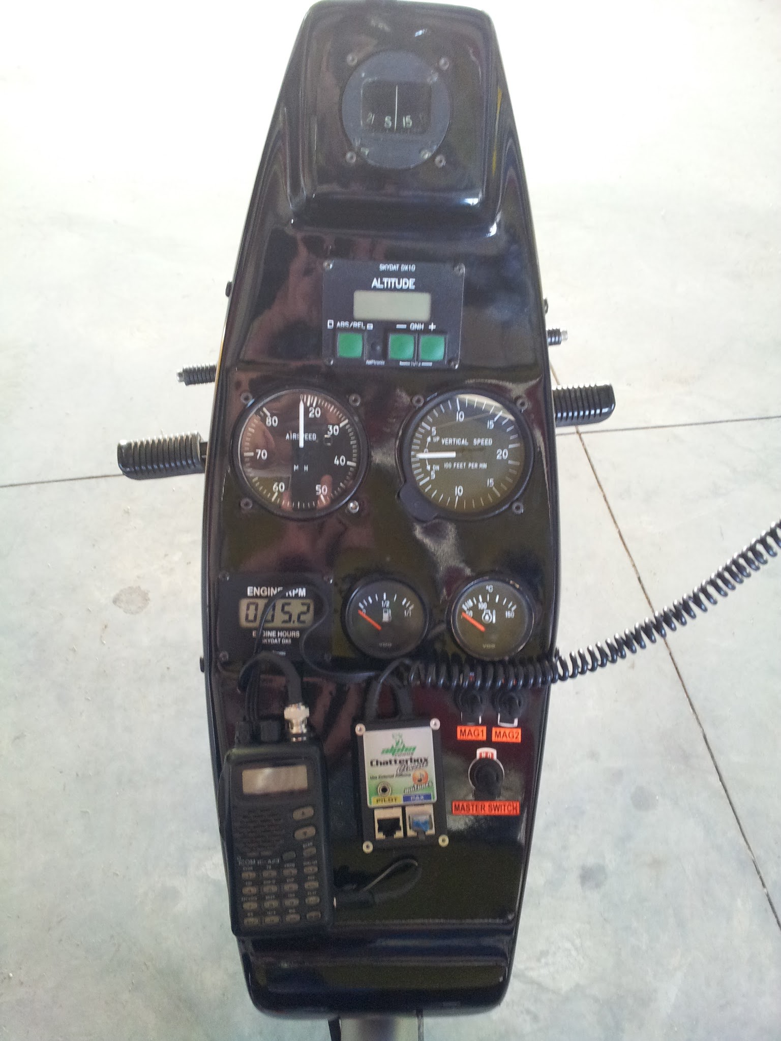
The instrument pod is located between the pilots legs.
The original instrument pod is pictured above. From top to bottom (and left to right), the instruments are as follows:- Compass,
- Altimeter,
- Air Speed Indicator (ASI),
- Vertical Speed Indicator (VSI),
- Engine RPM and Hour Meter,
- Fuel Level,
- Water Temperature,
- Radio,
- Intercom,
- Magneto Switches, and
- Master Switch.
The analog dials look nice and make a neat cockpit, but lack in functionality for cross country navigation. Also, the ASI was under-reading, the compass needed calibration and the Engine RPM Meter occasionally showed zeros. Time for an upgrade!
As hackers and engineers we are quick to think of all the potential features we can add with a few sensors, a micro-controller and an LCD screen. It wasn't long before I built the first prototype...
I installed a 128 x 64 graphic LCD module between the radio and the switches, integrating the intercom box into the pod and added the headset connectors to the bottom of the pod. My phone in the flight suit window pocket runs the Air Navigation Pro app, which gives me a moving map with all the airspaces. A PIC microchip, GPS module, some MEMS sensors and a Rotary Encoder added a few additional flight instruments:
- Ground Speed
- True Heading
- True Altitude
- Altitude at standard pressure (Flight Level)
- Date and Time
- Flight Time
- Pilot Checklist / Notes
- Battery Voltage
- Outside Air Temperature
- Headlight Control
- Heat-pad Temperature Control
- Engine RPM Meter
- Fuel Level
- Water Temperature
- USB Charging Port
So far so good... the only issue: feature creep!
This first prototype was hacked together on veroboard with parts I had lying around. With all the menus and functionality, the 24 KB program memory on the PIC18F4455 was quickly running out. Time for a proper design...
-
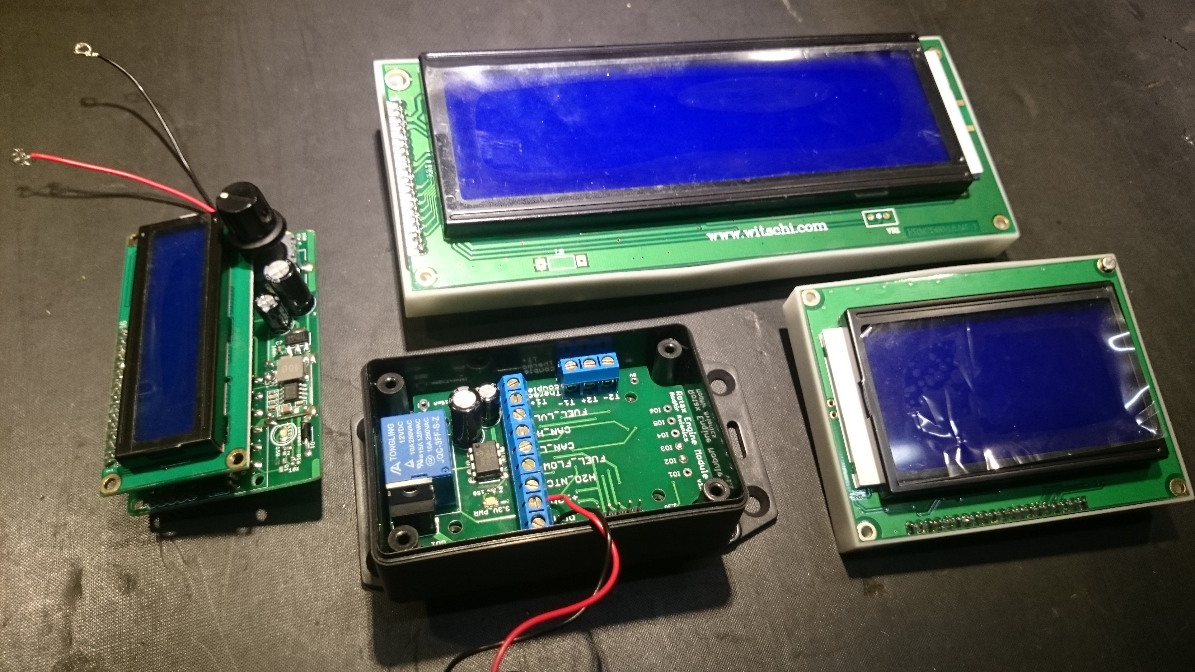
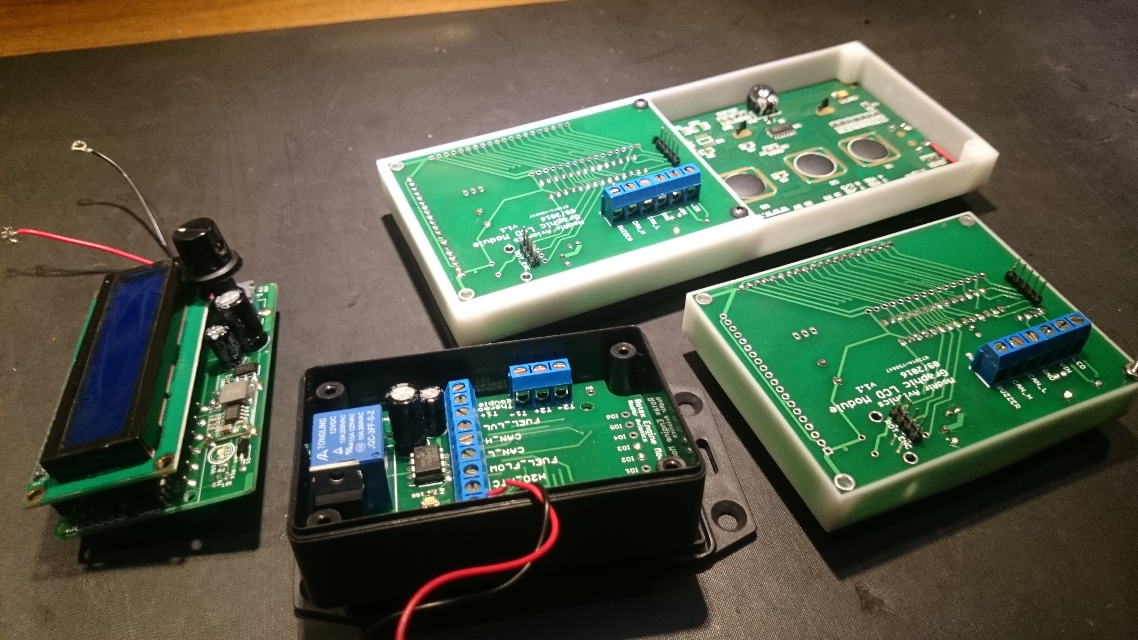
First Batch: Assembled Modules
02/05/2017 at 13:21 • 0 commentsFor the first manufacturing batch, I decided to focus on the bare essentials: LCD screen module and engine monitoring module. The screen module PCB was designed to fit some of the more common graphic and character LCDs from China. Here are some pictures after soldering and assembly.
ModAir - Modular Aviation Instruments
Open Source Avionics for Microlights and other Non-Type-Certified Aircraft