niko
niko-
Things have changed a lot
04/22/2017 at 09:28 • 0 commentsI hadnt made any updates here because lack of time, but the bucket have changed a lot.
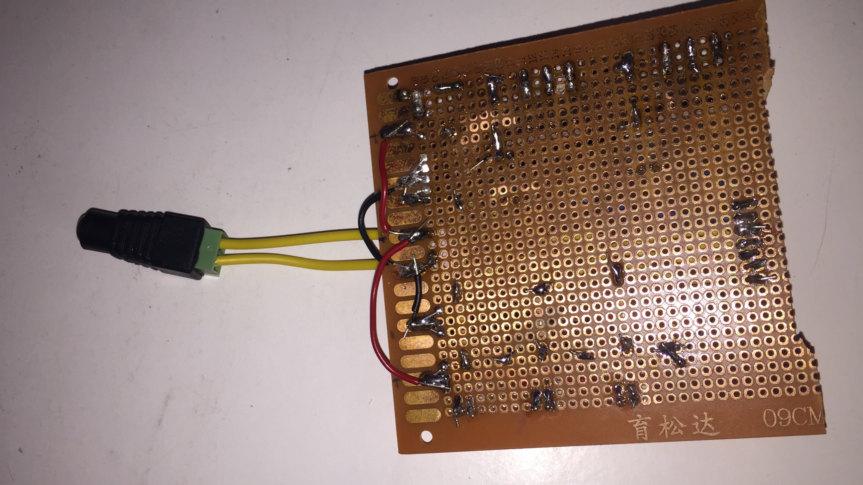
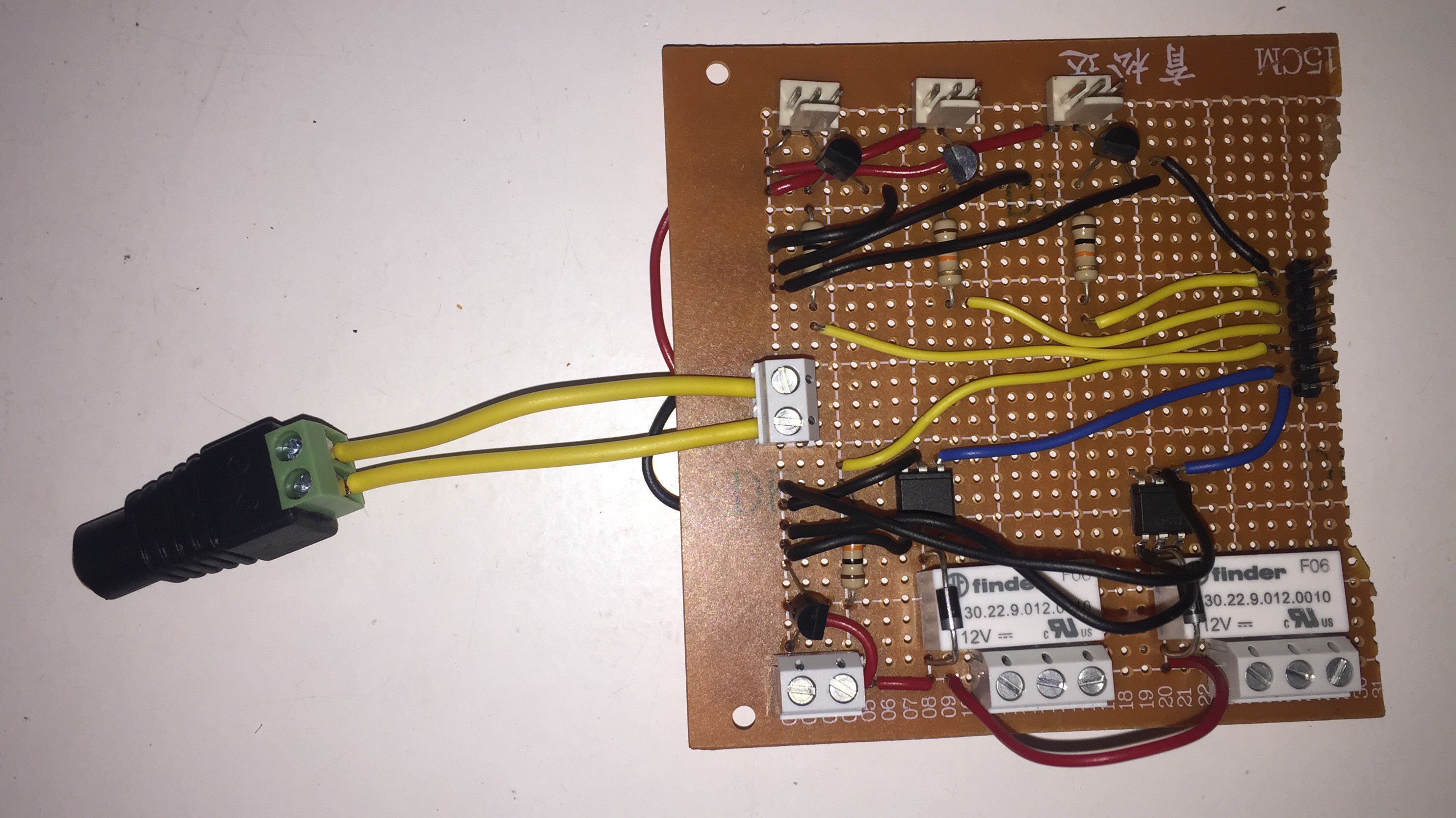
Finally, assembled first prototype for the circuit board, already i have lot of changes in mind, but at least it took out a lot of cables and mess. Heres a shot:
![]()
Basically, powers 2 12v fans for the air flow and one to cool the leds, also uses has 2x 12V 6A relays to switch on and off the power to the main and side lights(also added them to the bucket) and has a connection for the water pump(which is still in development). Takes the power from a sauvaged 12V Wall power source and everithing is turned on and off by transistors controlled from the arduino.
![]()
Im now trying to develop a second model with a lot lot of updates, to make it even easier and more functional.
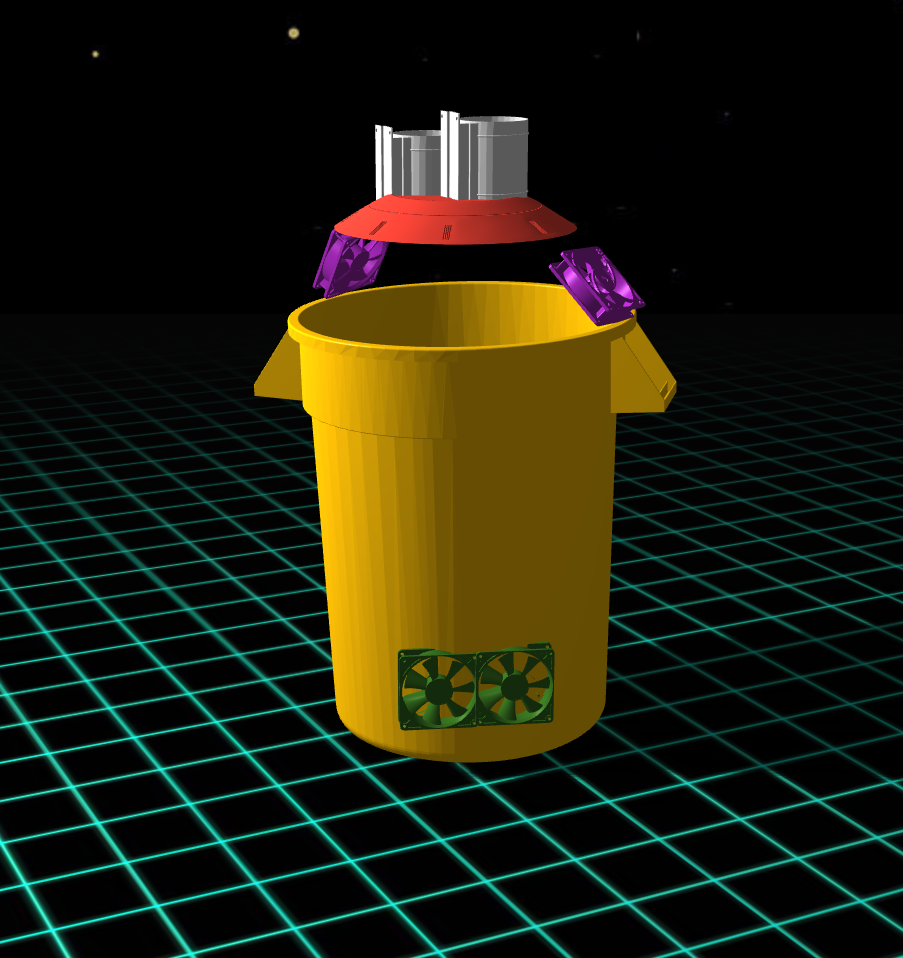
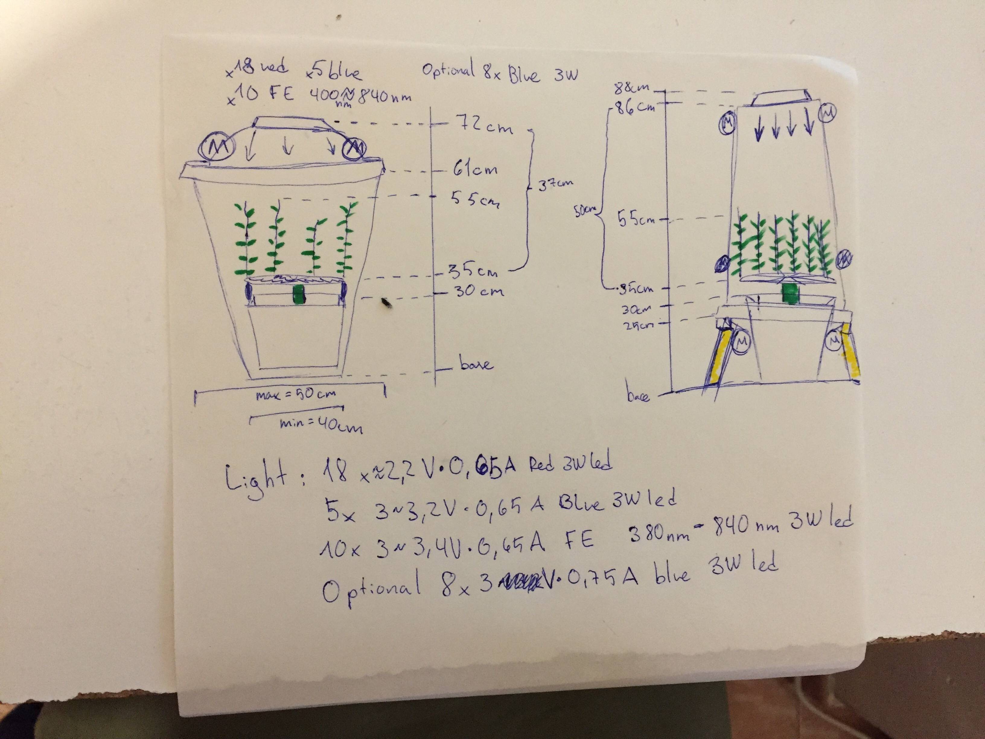
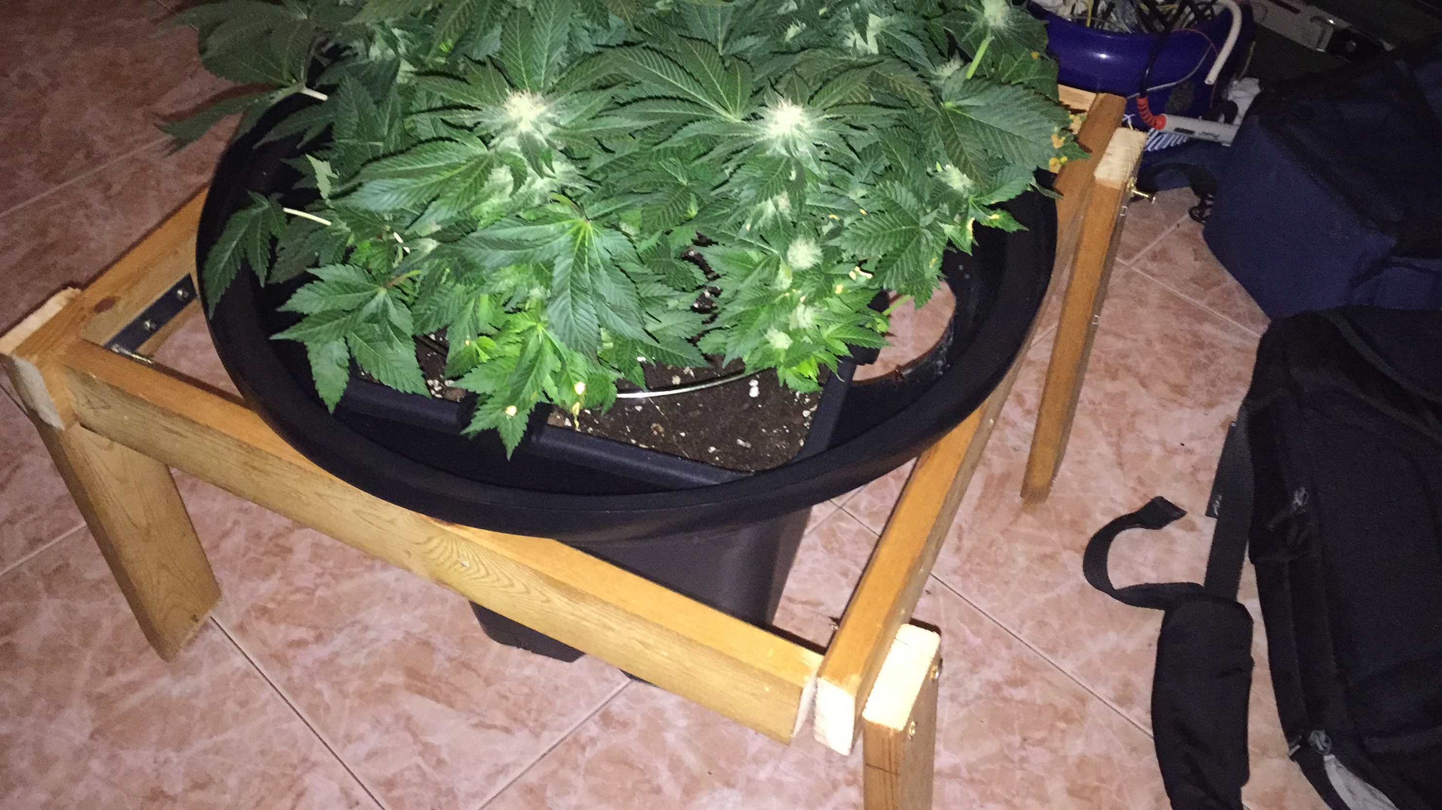
Othe major development was the redesign of the bucket. The top leafs where getting burned, so i decided to add more space vertically, i did a little sketch about it:
![]()
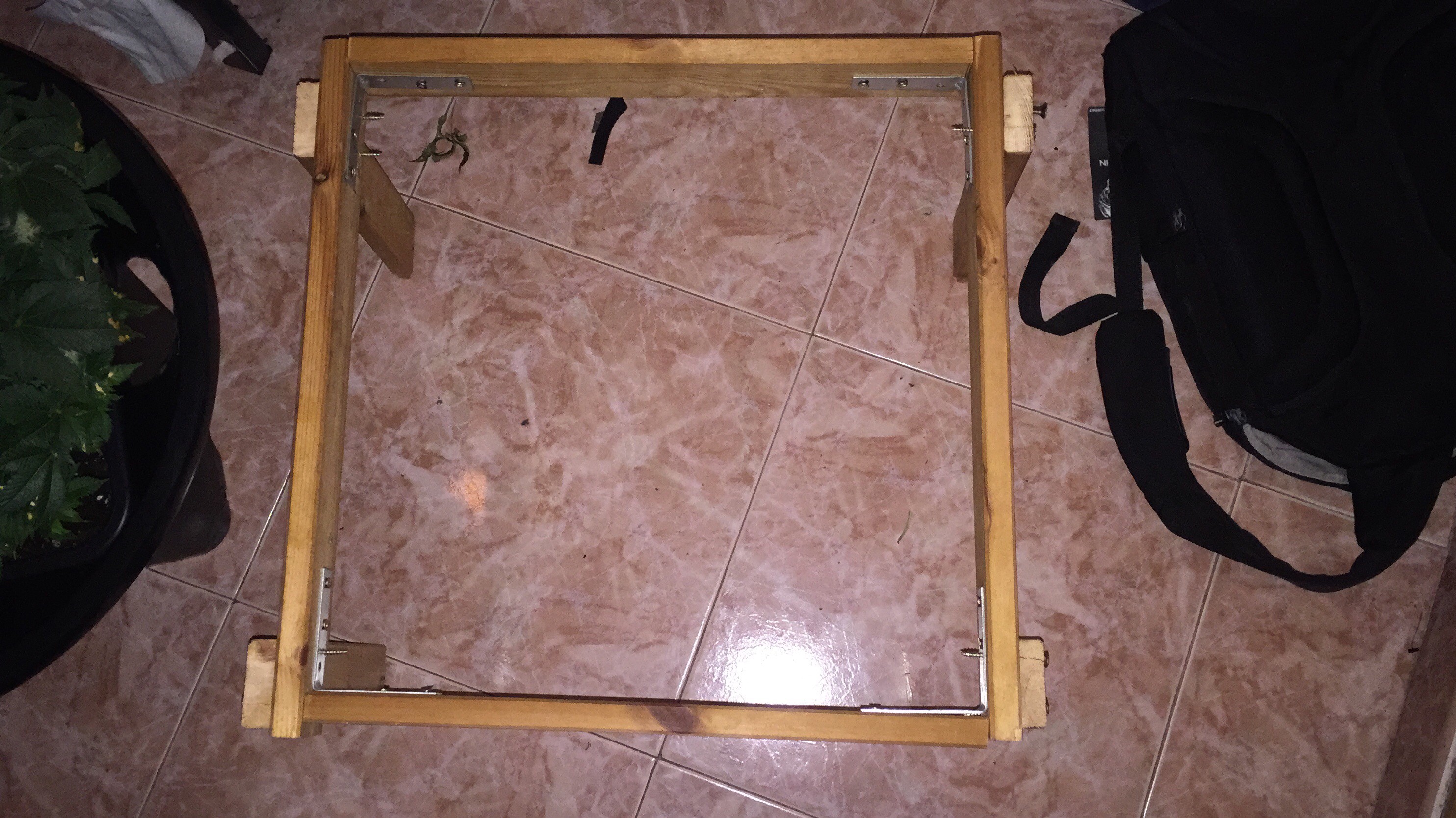
I did a little base with sauvaged pine wood from a matress:
![]()
![]()
and it turned out pretty well alltogether:
![]()
![]()
The air is flowing pretty well just with the 2x top fans and two passive intakes at bottom, also i added SMD 3560 as side lights, powered by 12V 1A wall power sources i had at home, and they turned to work pretty well, as some lower zones of the plant were getting very little light and this helped to develop that parts.
-
Minor updates
01/28/2017 at 03:15 • 0 commentsThis week started university again so less time will be invested in this project, but at the moment works.
I've updated the code on GitHub
Ive updated the way the lights are controlled and put a start-end time for each light.
also mae larger the time between conditions measurement as i sont want to make the mysql very large and a reading of temperature every 20 sec is unnecesary
So right now is working autonously, except for the watering system.
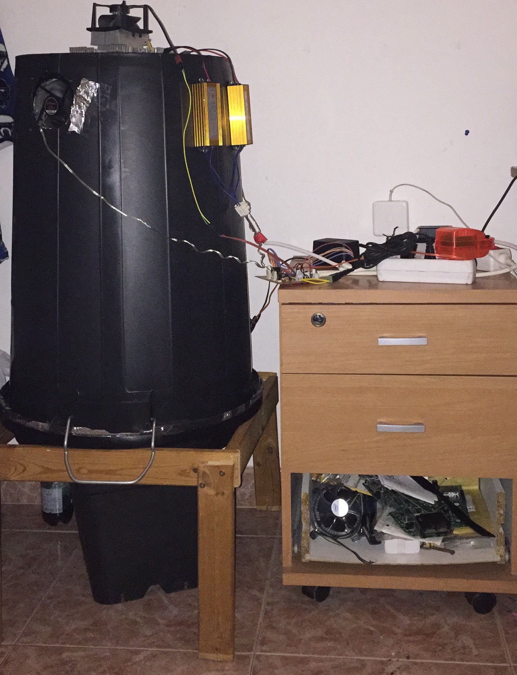
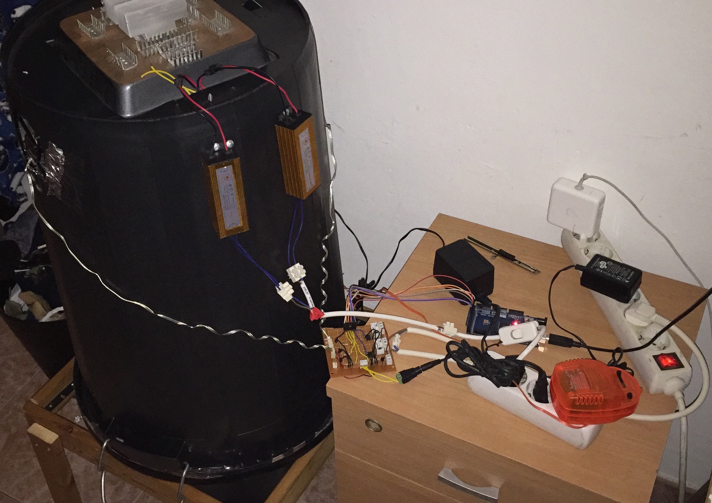
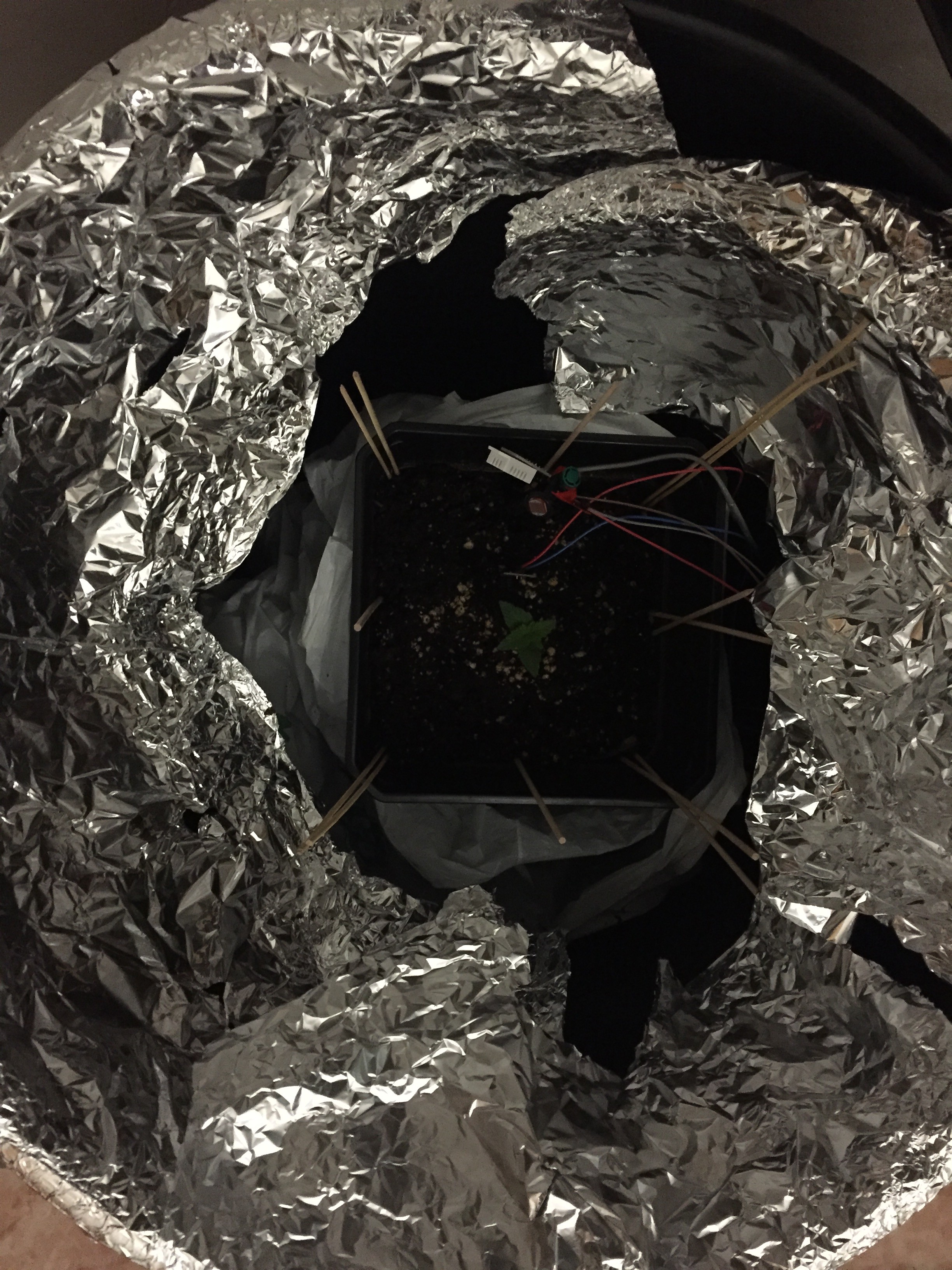
I also upgraded the bucket, mounting the fans and putting led lights in the top part, im pretty happy with the result.
By the moment 1 fan is taing air in and the other one out, untill i mount the bottom fans.
Also lights get a bit hot (maybe 50-60 *C) because i pasted them not the best way, so maybe this will be modified, if somebody makes something similar, dont put all the leds that turn on at same time together. I pasted by the moment the small heatsinks, but maybe they will be replaced by bigger/better ones
![]()
![]()
As the plant is small, the led lenses arent mounted yet and the plant is over some small bucket
![]()
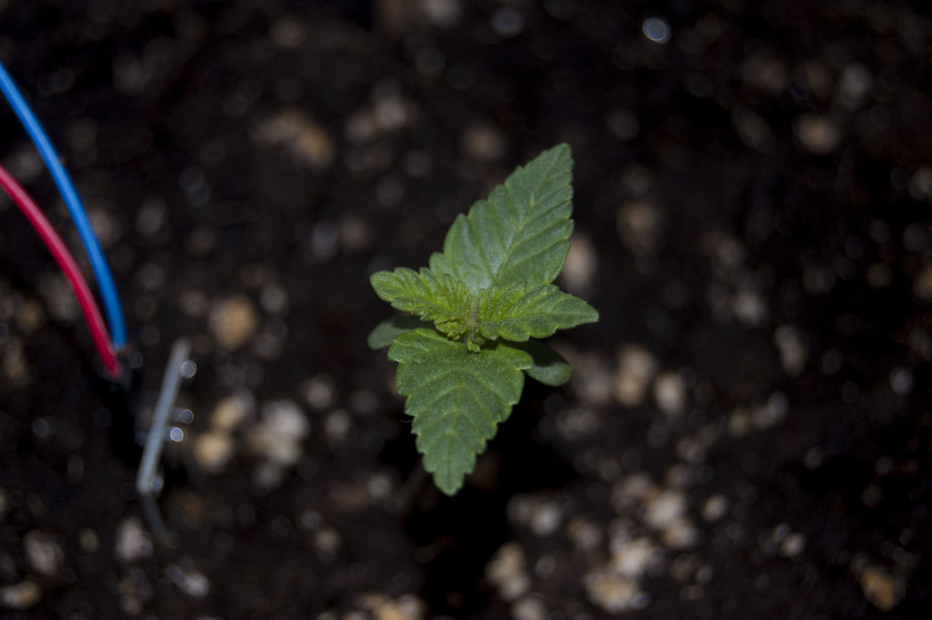
I think im not doing things very bad if the plant looks so healthy :)
![]()
-
Getting stuff done
01/21/2017 at 02:57 • 0 commentsHave been working in this stuff all week so some mayor things have been done.
Also some minor things were bought so, pricelist should be actualized
##LIGHT
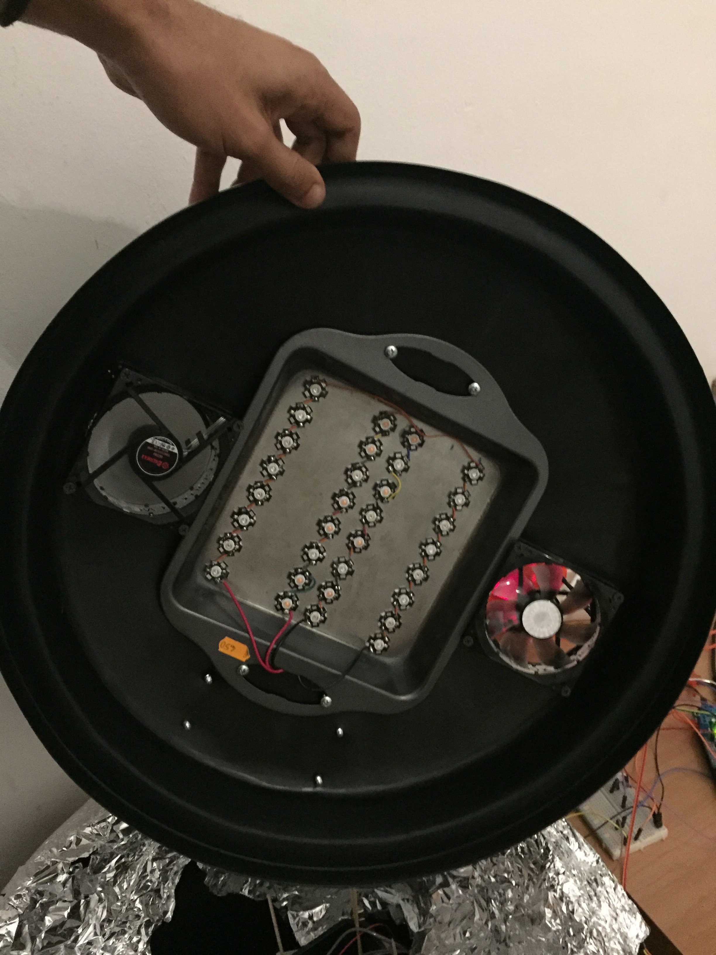
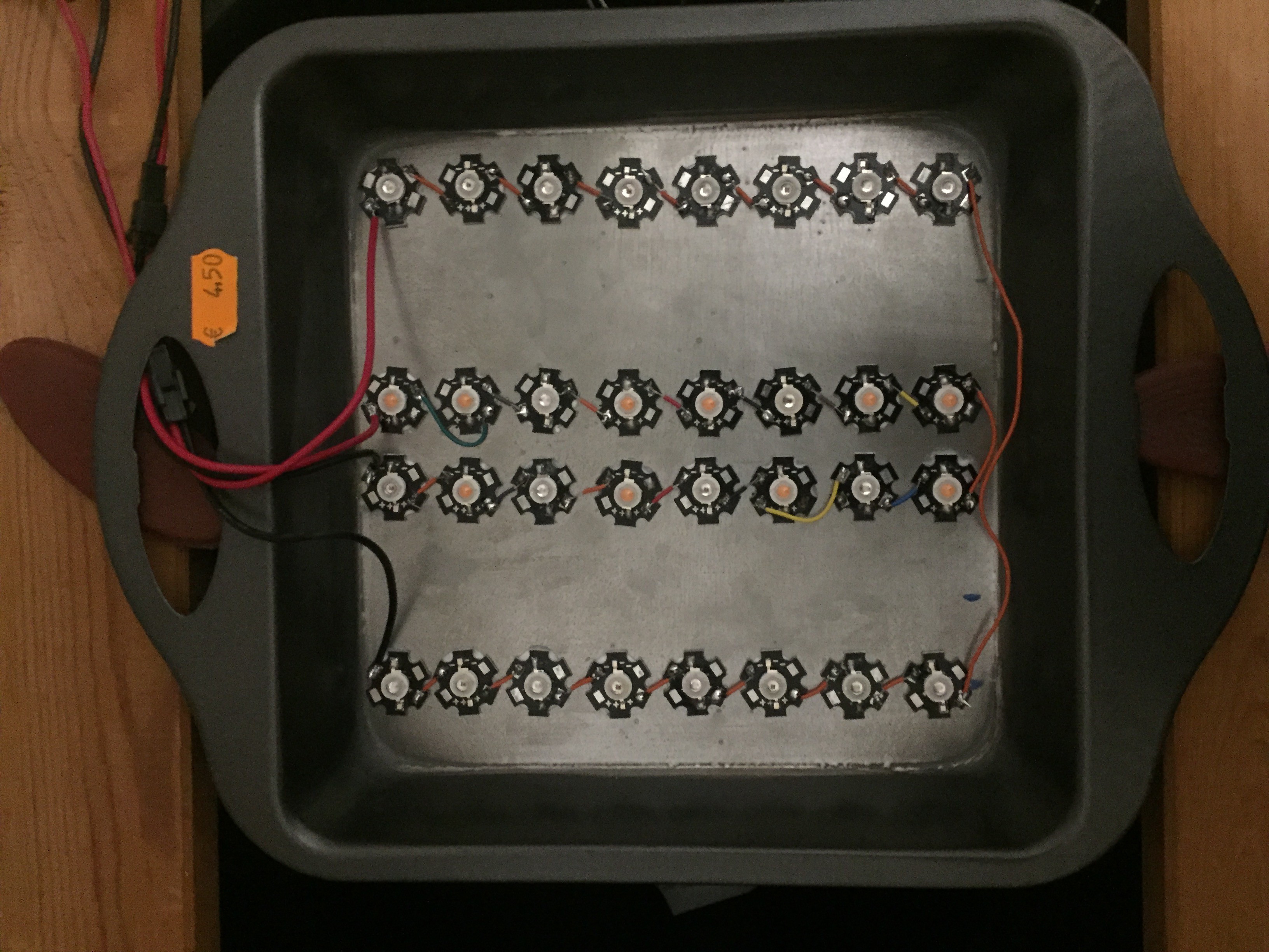
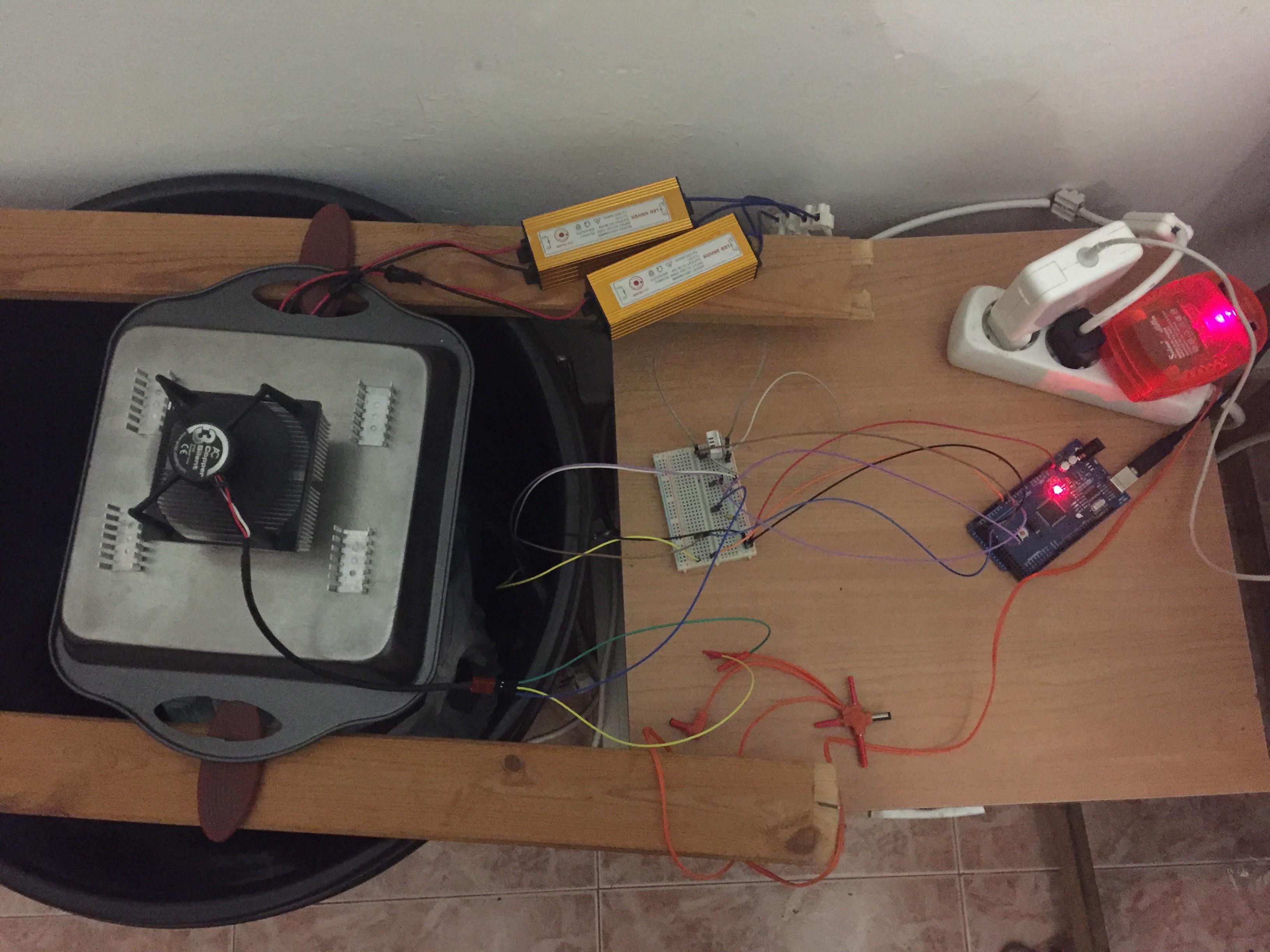
-Bought a squared metal stuff to paste the LED lightning system on it, in total 32 x 3W LEDs to speed up plant growth
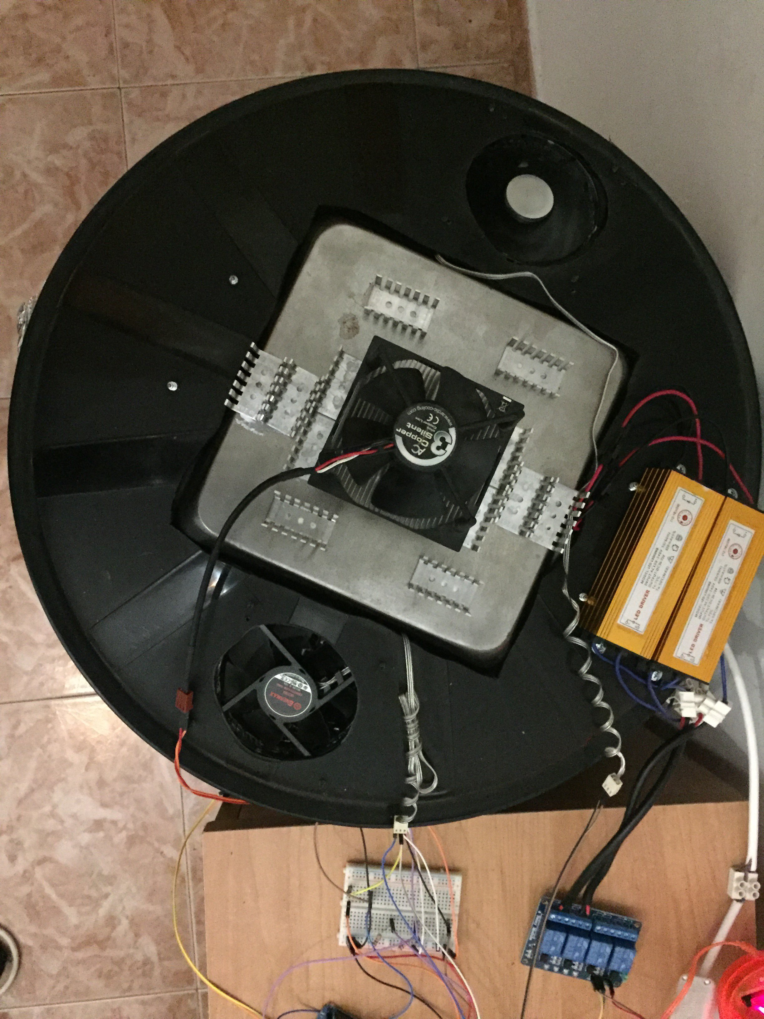
-Welded all the connetions and powered it with the LED drivers
![]()
-Added one of the PC fans at top and some heatsinks. Was planning to add 2 of that pc fans but i think with that one and some more heatsinks is enough. Bougth also 12V 1A power connector for the pc fan. Here you can see it in place with the arduino gathering data
![]()
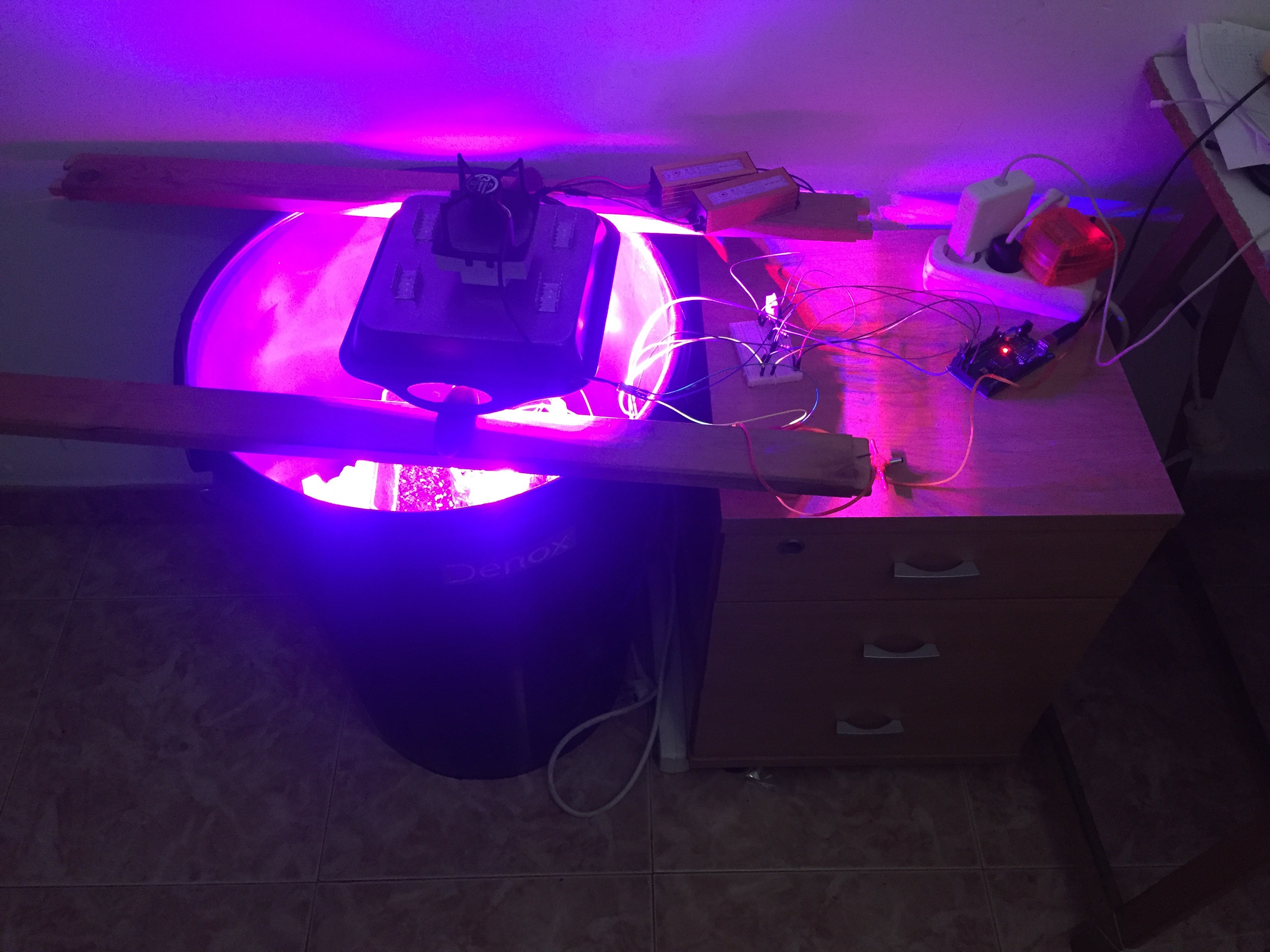
-Here you can see it in action
![]()
##Arduino and rPi data logger
Some further advances had also made been on the software part
I've uploaded the program to : Arduino Plant Bucket Github
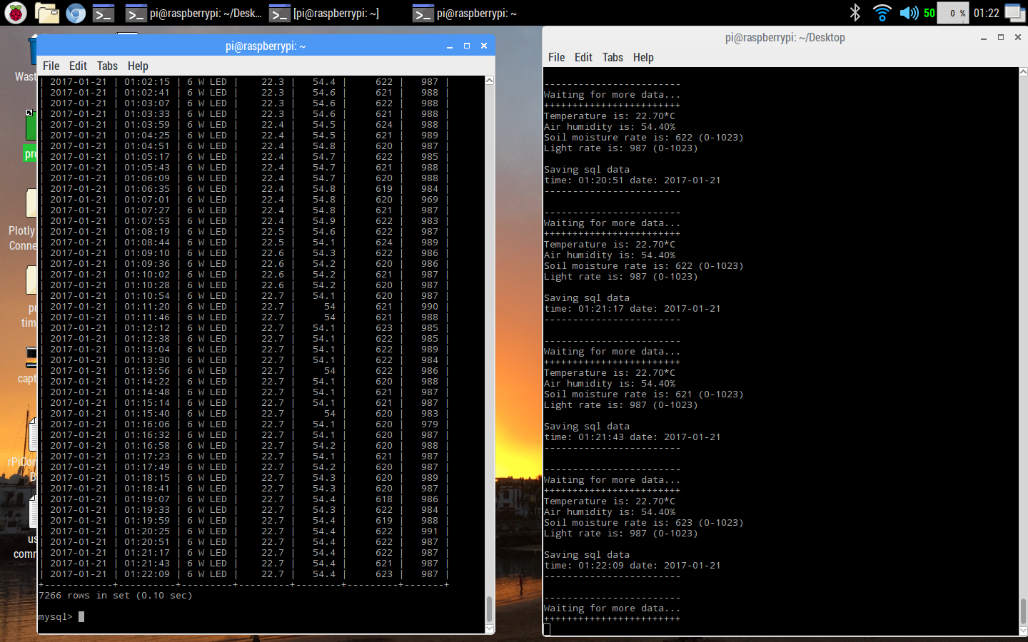
By the moment, the program in the arduino reads all for sensors, and sends the info by serial to the rPi, this one waits for all the data of the row, and inserts it in a previosly created MySql database
Here you can see it working:
![]()
The programs need further programming as i'm not very happy how the sql data is organized(im a complete sql NOOB).
Light and fan control and the watering system are not implemented.
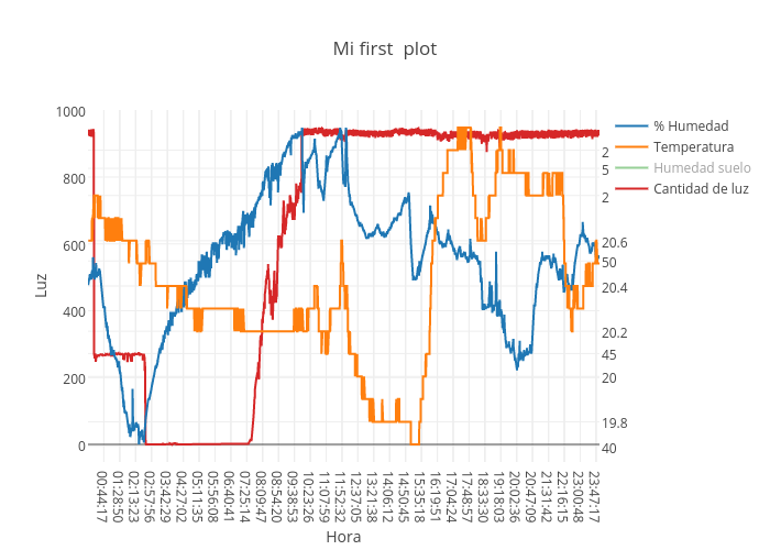
At lest i can try to have an idea of how is the enviroment inside of the bucket graphing the data with plot.ly
This is how my first day plot looks like:
![]()
Reference links:Transfer Arduino Data to MySQL Database on Raspberry Pi - Youtube
##EXTRA!!
if somebody got reading until here, thing that i supose will never happen, i am also learning a bit of photography, and did some practice timelapses with my old nikon d40 and gphoto2 and the rPi, about the first days of the Cream caramel plant. Will try to do some more next weeks,
Here is the unedited result:
-
Wiring update and sensors test
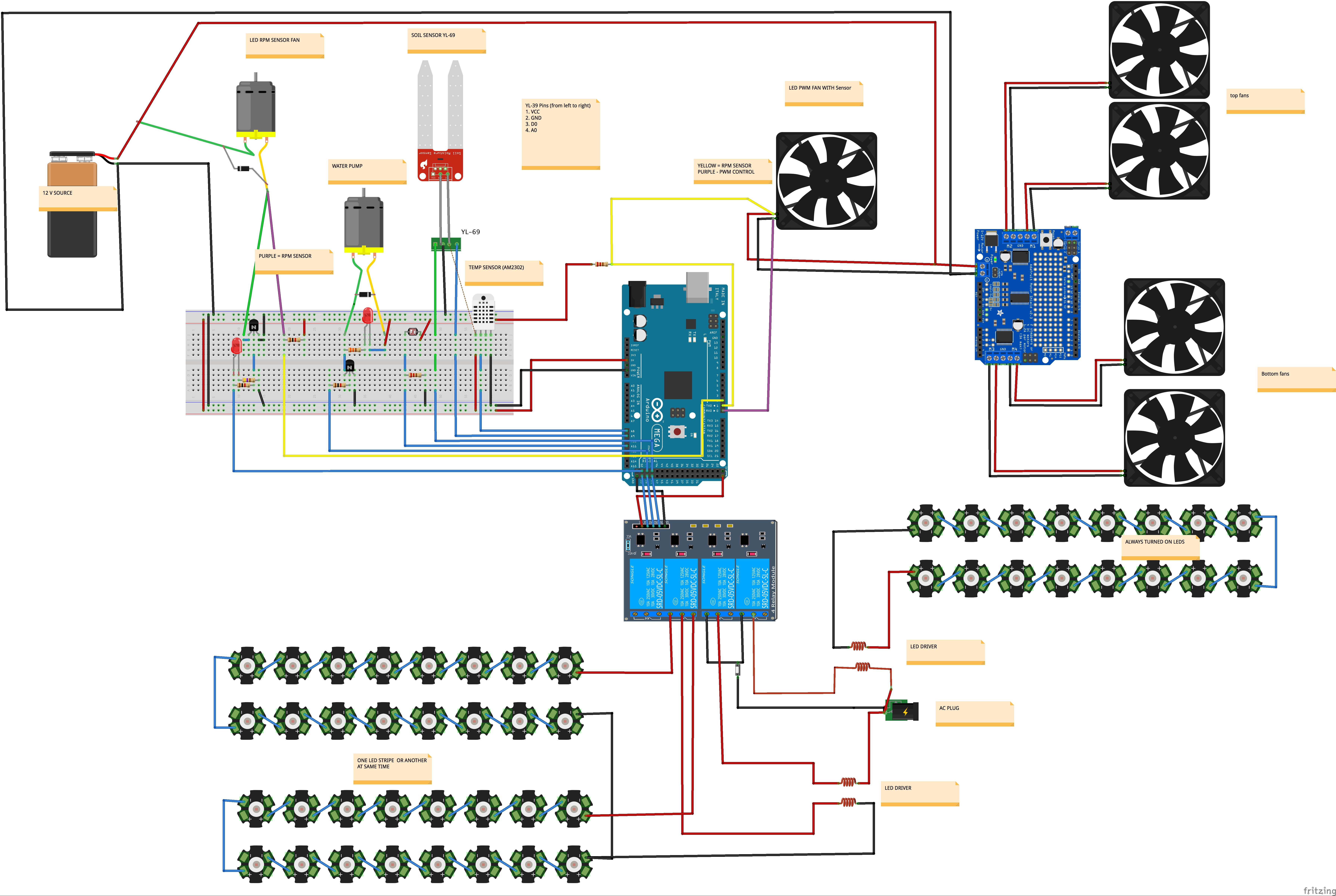
01/12/2017 at 20:28 • 0 commentsSo after making the Component desglose, i decided to make a clear wiring diagram proposal and creating the arduino program.
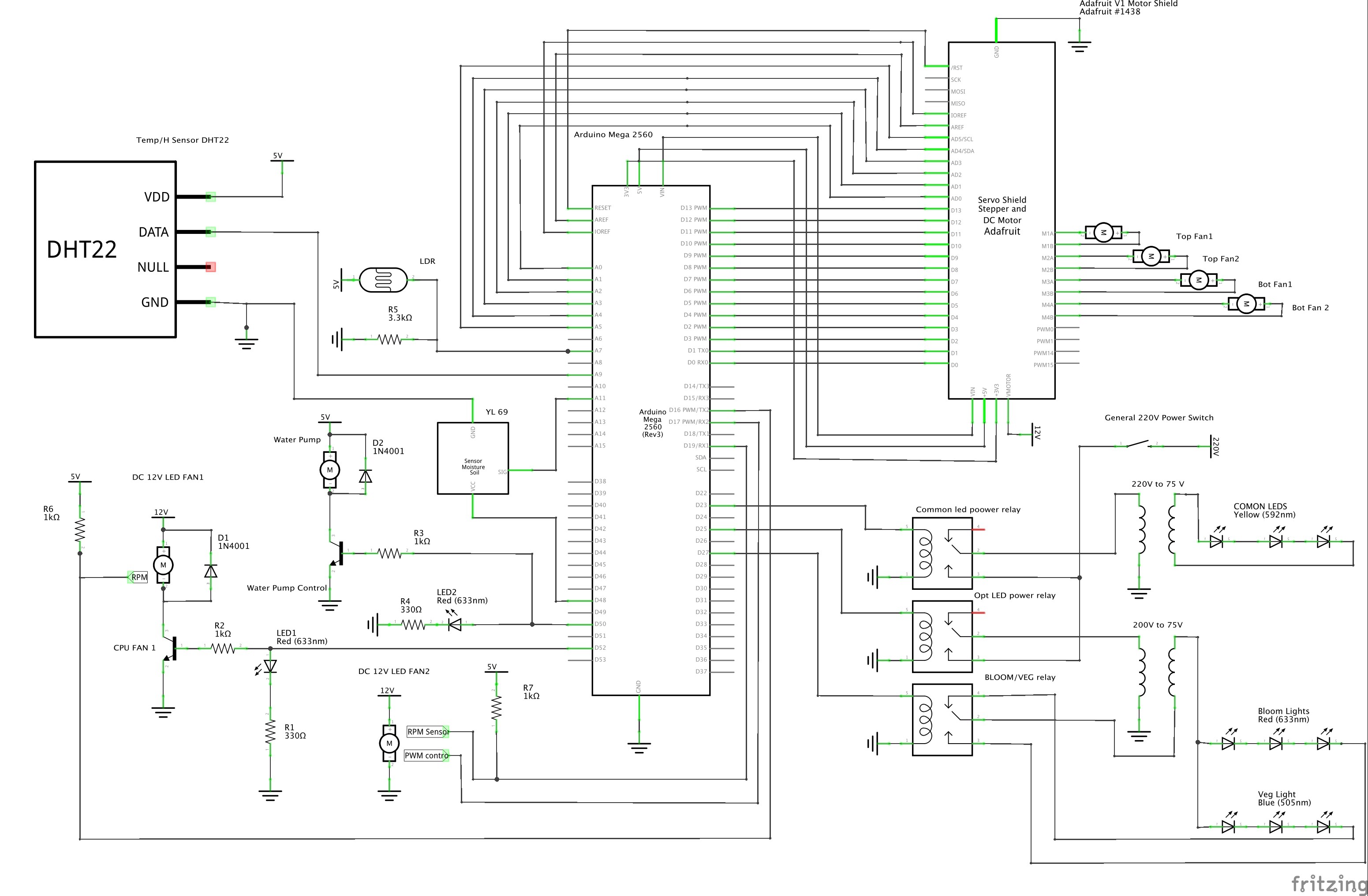
The new general wiring diagram, it's not definitive, will be actualized as needed to mount the project, especially the ports to which the sensors are connected, but starts to look clean and organized.
![]()
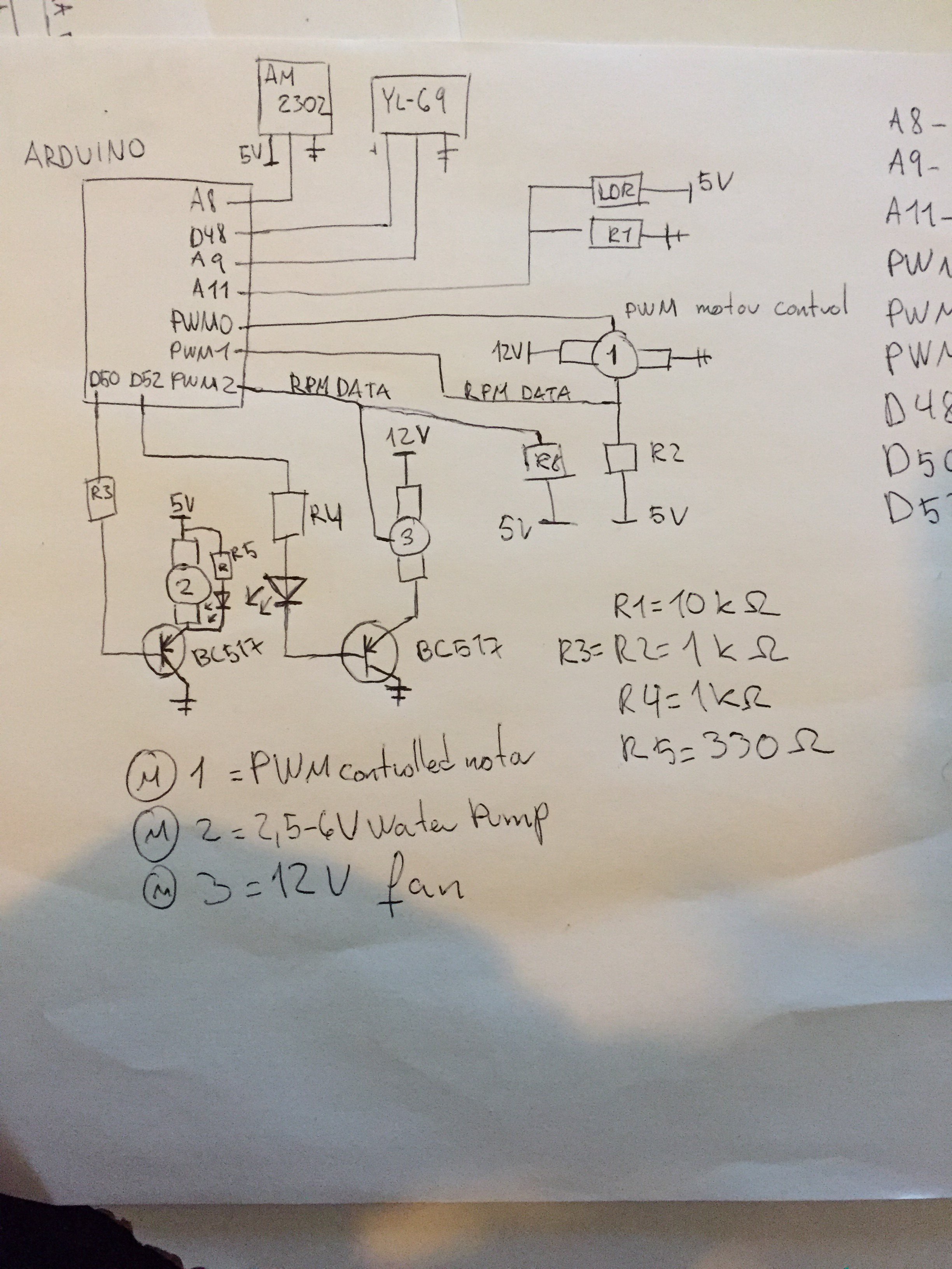
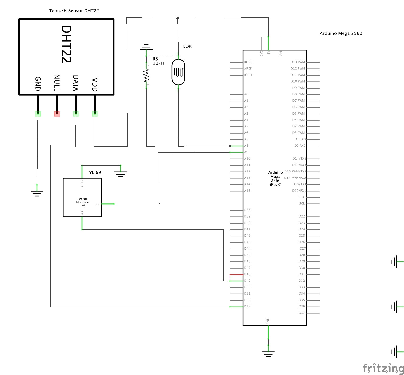
For the first part of the program i decided to create the basic functions that will gather data from the sensors, also for testing them, and send that data thru USB serial to the arduino.
The circuit is showed under, the cutted lines from ground to 5V and between PINs D48 & D49 is because of some fritzing error, they shouldn't be included.
![]()
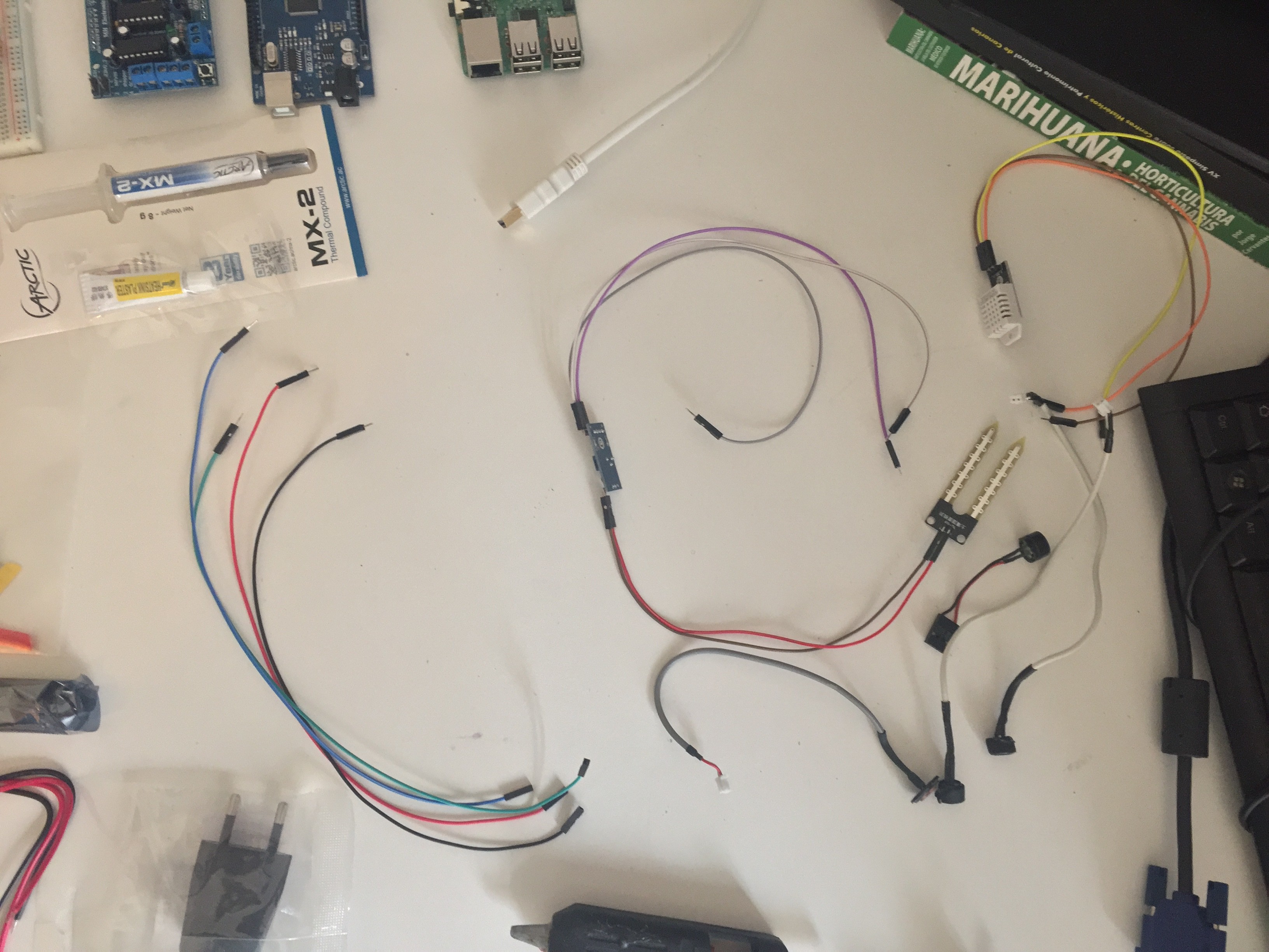
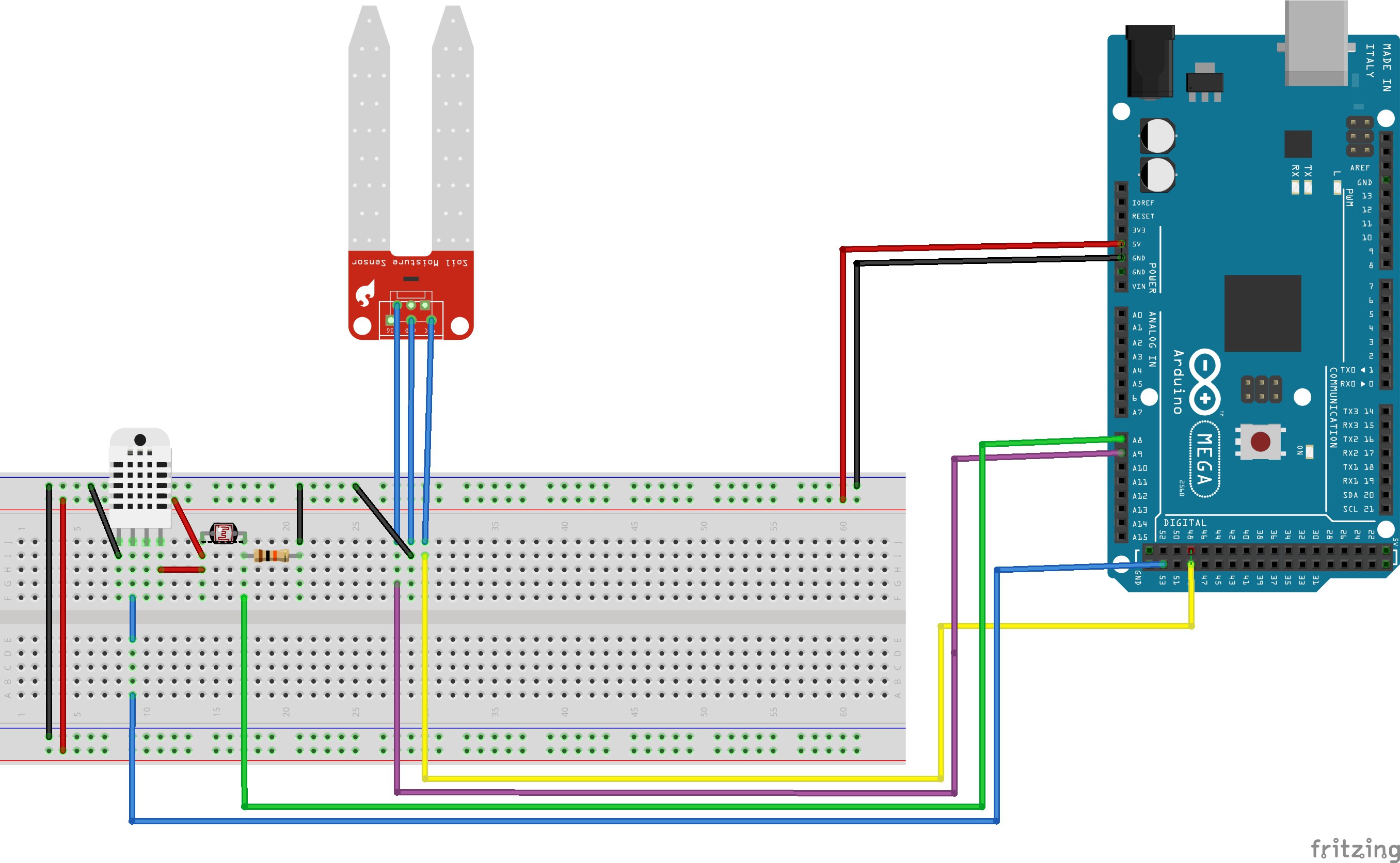
This is the protoboard mounting:
DHT22 Data PIN 53 - Blue
YL-69 Turn on PIN 49 - Yellow
YL-69 Data PIN A9 - Purple
LDR Data PIN A8 - Green
![]()
For creating this cricuit i gathered information about them from the net, best info i got from:
Adafruit - Using a DHTxx sensor
Read LDR Values on arduino - Luis LLamas (Spanish)
Using the YL-39/YL-69 Soil himidity sensor with arduino
And this is the result test program, reads values from the sensor pins and send it thru USB, while is taking measurements, onboard led turns on:
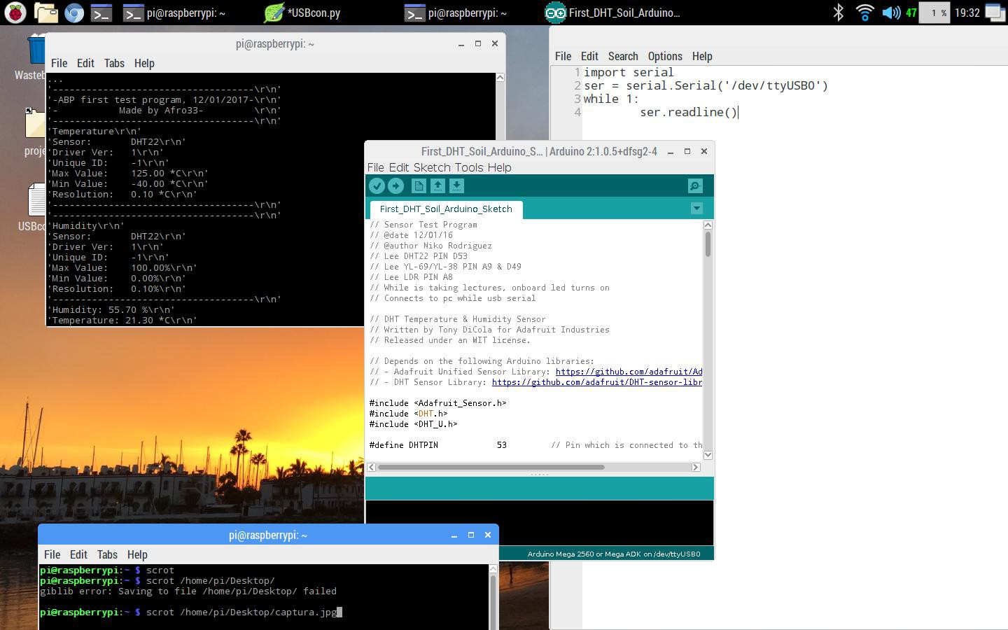
// Sensor Test Program
// @date 12/01/16
// @author Niko Rodriguez
// Lee DHT22 PIN D53
// Lee YL-69/YL-38 PIN A9 & D49
// Lee LDR PIN A8
// While is taking lectures, onboard led turns on
// Connects to pc while usb serial
// For arduino Mega 2560

// DHT Temperature & Humidity Sensor
// Written by Tony DiCola for Adafruit Industries
// Released under an MIT license.

// Depends on the following Arduino libraries:
// - Adafruit Unified Sensor Library: https://github.com/adafruit/Adafruit_Sensor
// - DHT Sensor Library: https://github.com/adafruit/DHT-sensor-library

#include <Adafruit_Sensor.h>
#include <DHT.h>
#include <DHT_U.h>

#define DHTPIN            53         // Pin which is connected to the DHT sensor.

// Uncomment the type of sensor in use:
//#define DHTTYPE           DHT11     // DHT 11
#define DHTTYPE           DHT22     // DHT 22 (AM2302)
//#define DHTTYPE           DHT21     // DHT 21 (AM2301)

// See guide for details on sensor wiring and usage:
//   https://learn.adafruit.com/dht/overview

DHT_Unified dht(DHTPIN, DHTTYPE);

uint32_t delayMS;


// YL-39 + YL-69 humidity sensor
byte humidity_sensor_pin = A9;
byte humidity_sensor_vcc = 49;


//LDR
int LDR_Pin = A8; //analog pin 0

//Onboard LED
int defaultLed = 13;

void setup() {
  // Init the onboard LED
  pinMode(defaultLed, OUTPUT);

  // Init the humidity sensor board
  pinMode(humidity_sensor_vcc, OUTPUT);
  digitalWrite(humidity_sensor_vcc, LOW);

  // Setup Serial
  Serial.begin(9600);
  dht.begin();
  // Print temperature sensor details.
  sensor_t sensor;
  dht.temperature().getSensor(&sensor);
  Serial.println("------------------------------------");
  Serial.println("-ABP first test program, 12/01/2017-");
  Serial.println("           -Made by Afro33-         ");
  Serial.println("------------------------------------");
  Serial.println("Temperature");
  Serial.print  ("Sensor:       "); Serial.println(sensor.name);
  Serial.print  ("Driver Ver:   "); Serial.println(sensor.version);
  Serial.print  ("Unique ID:    "); Serial.println(sensor.sensor_id);
  Serial.print  ("Max Value:    "); Serial.print(sensor.max_value); Serial.println(" *C");
  Serial.print  ("Min Value:    "); Serial.print(sensor.min_value); Serial.println(" *C");
  Serial.print  ("Resolution:   "); Serial.print(sensor.resolution); Serial.println(" *C");
  Serial.println("------------------------------------");

  // Print humidity sensor details.
  dht.humidity().getSensor(&sensor);
  Serial.println("------------------------------------");
  Serial.println("Humidity");
  Serial.print  ("Sensor:       "); Serial.println(sensor.name);
  Serial.print  ("Driver Ver:   "); Serial.println(sensor.version);
  Serial.print  ("Unique ID:    "); Serial.println(sensor.sensor_id);
  Serial.print  ("Max Value:    "); Serial.print(sensor.max_value); Serial.println("%");
  Serial.print  ("Min Value:    "); Serial.print(sensor.min_value); Serial.println("%");
  Serial.print  ("Resolution:   "); Serial.print(sensor.resolution); Serial.println("%");
  Serial.println("------------------------------------");
  // Set delay between sensor readings based on sensor details.
  delayMS = sensor.min_delay / 1000;
  delay(1000);
  //dht.begin();
}

int read_humidity_soil() {
  // Gets Soil humidity (0-1024) first turns on sensor
  ledOn();
  digitalWrite(humidity_sensor_vcc, HIGH);
  delay(500);
  int value = analogRead(humidity_sensor_pin);
  digitalWrite(humidity_sensor_vcc, LOW);
  ledOff();
  return 1023 - value;
}

double read_humidity_DHT() {
  // Get humidity event and print its value.
  ledOn();
  sensors_event_t event;
  dht.humidity().getEvent(&event);
  if (isnan(event.relative_humidity)) {
    Serial.println("Error reading humidity!");
    ledOff();
    return 0;
  }
  else {
    ledOff();
    return event.relative_humidity;
  }

}

double read_temp() {
 sensors_event_t event;
  // Get temperature event and print its value.
  ledOn();
  dht.temperature().getEvent(&event);
  if (isnan(event.temperature)) {
    Serial.println("Error reading temperature!");
    ledOff();
    return 0;
  }
  else {
    ledOff();
    return event.temperature;
  }
}

int read_light() {
  // Reads a LDR connected to analog port with 10K resistor
  ledOn();
  delay(1000);
  ledOff();
  return analogRead(LDR_Pin);
}

void ledOn() {
  digitalWrite(defaultLed, HIGH);
}

void ledOff() {
  digitalWrite(defaultLed, LOW);
}
void loop() {

  Serial.print("Humidity: ");
  Serial.print(read_humidity_DHT());
  Serial.println(" %");
  delay(10000);

  Serial.print("Temperature: ");
  Serial.print(read_temp());
  Serial.println(" *C");
  delay(10000);

  Serial.print("Soil Humidity Level (0-1023): ");
  Serial.println(read_humidity_soil());
  delay(10000);

  Serial.print("Light Level (0-1023): ");
  Serial.println(read_light());
  delay(10000);
}
The usb serial data gathering on the Rpi was easily resolved using Oscar Liang's tutorial, here's the blog link:
Oscar Liang - Connect raspberry pi and arduino with USB cable
Heres a screenshot with the result:
![]()
In the next days, i'm going to collect all the data from the usb on the rPi and create some charts and graphics with them.
Also relay board must be tested and LED panel construction must start, as first seeds were yesterday putted in the pot, actually they're with a CFL lamp, so time isn't our ally.
Thanks for all who collaborate sharing tutorials and helping other people on forums and blogs, without all that people this wouldnt be possible.
-
Component Check and Price
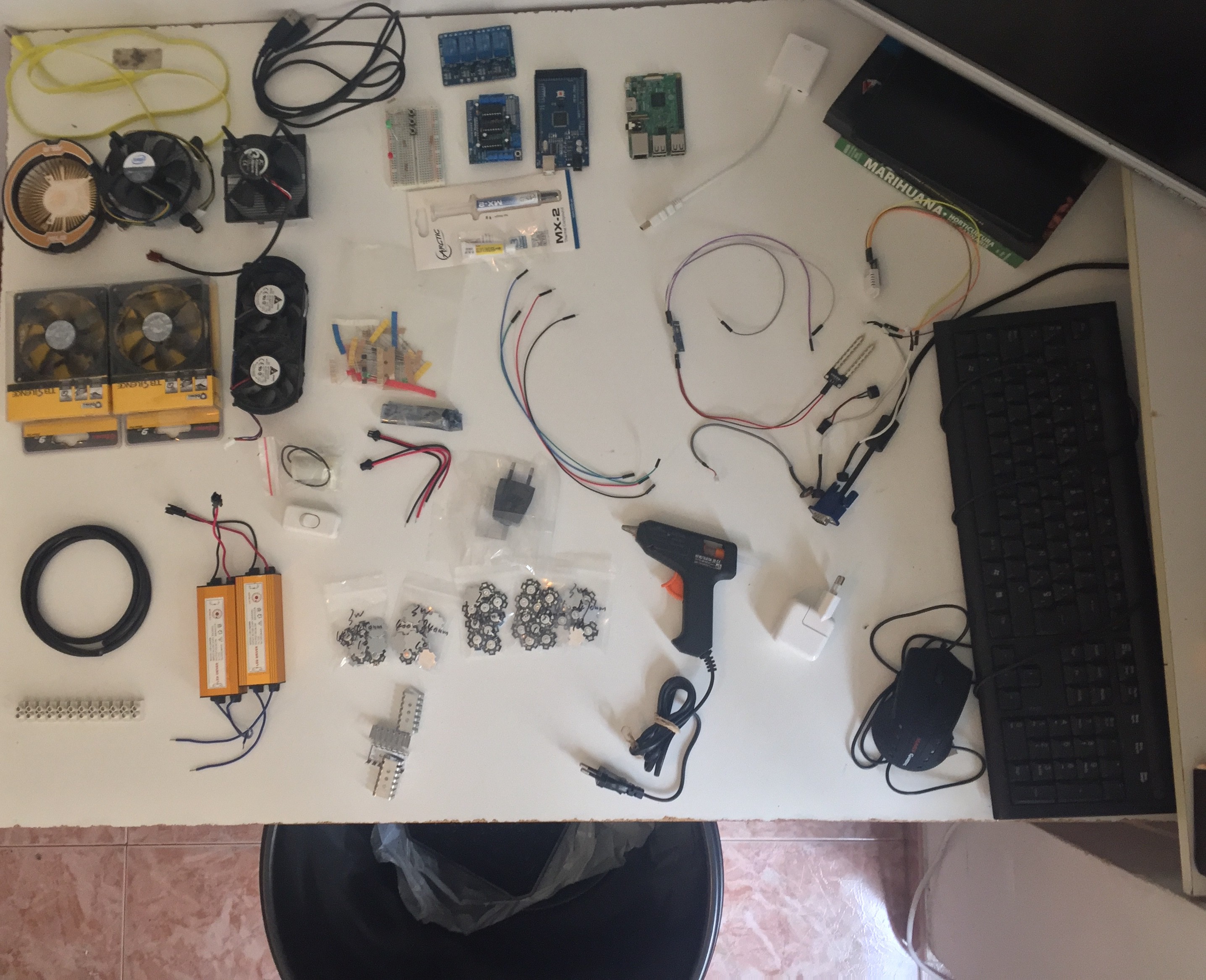
01/11/2017 at 15:11 • 0 commentsI already bought some of the last things i need to start to build, seed already has germinated so yesterday was put on soil, i want to start taking measurements with the Arduino and Sensors, so before that i decided to make a sum up of everithing i have need and what still i need and to make an estimated cost of the project:
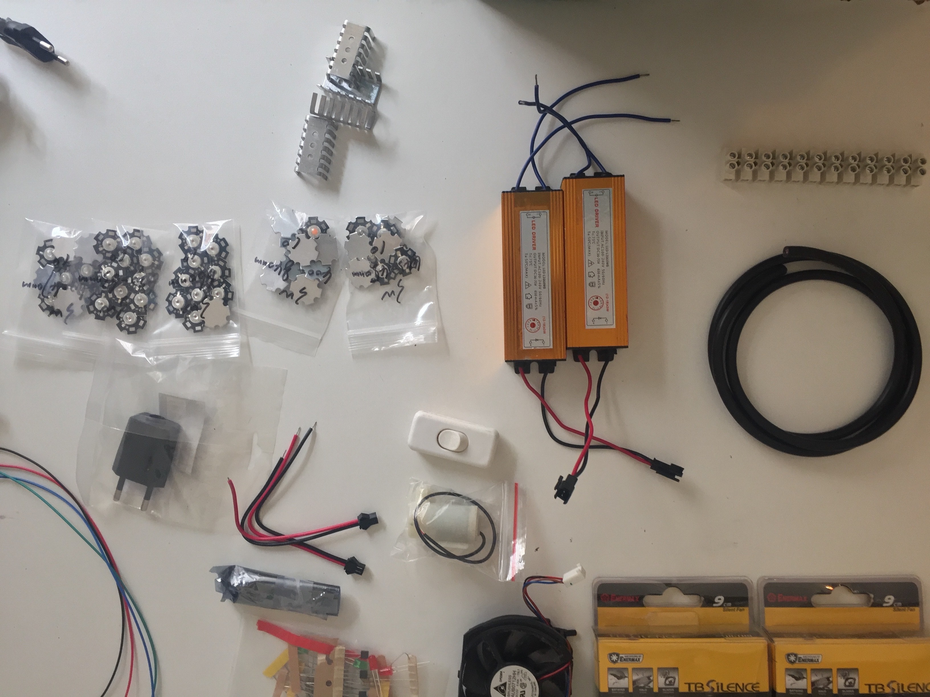
##Here is a photo of all i already got:
![]()
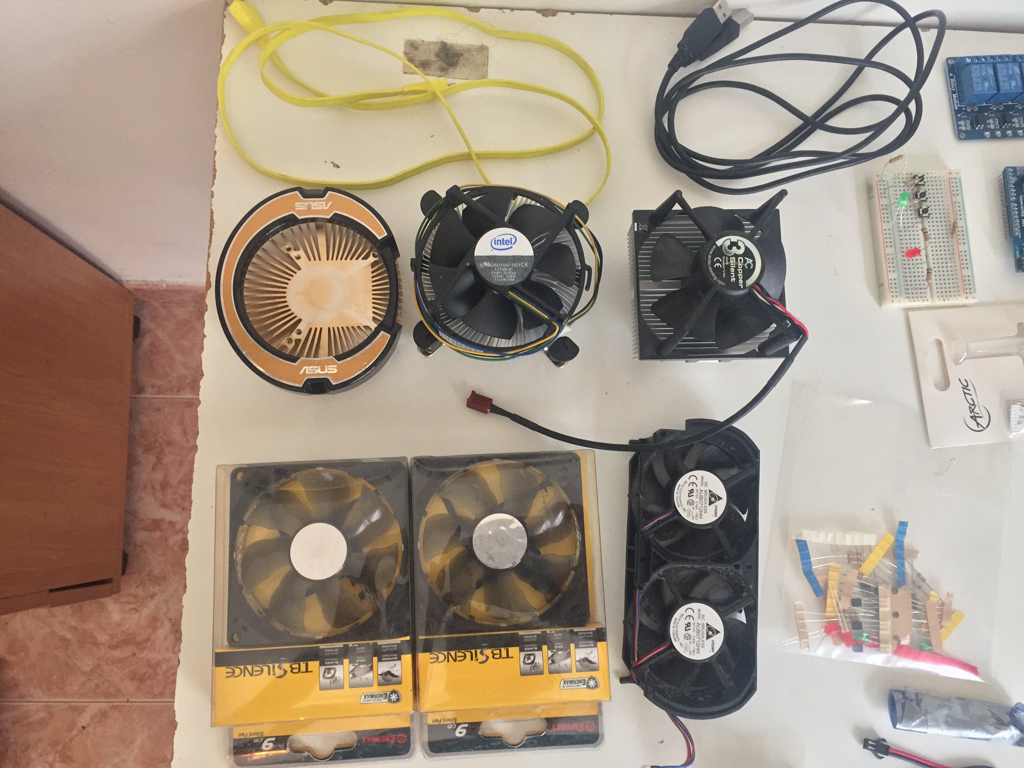
##Fans, Heatsinks and usb cables:
USB A - MicroUSB (Salvage 2 €)
USB A - USB B (Salvage 2 €)
Heatsink GPU (Salvage 5 €?)
Intel 12V CPU FAN PWN Controlled (Salvage 5 €?)
Old Salvage 12V with RPM speed hall sensor (Salvage 5 €?)
2x90mm CPU Fans (Salvage 5 €?)
Xbox 2x70mm Fans (Salvage 5 €?)
![]() ##Led Drivers and 3W leds:
##Led Drivers and 3W leds:4x Heatsinks (0,60 €)
1m 220V cable, Conectors, AC power plug, general AC switch (Salvage 2 €)
2,5-6V Aquarium water pump (3,98 $)
10x 3W LED Full Espectrum !
10x 3W LED 445-450 nm ( Far Red) !
10x 3W LED460-470 nm (Red) !
10x 3W LED 620-630 nm (Blue) !
10x 3W LED 660 nm (Royal Blue) V
2x 36-75V 650 mA LED Driver ! 56,89 € ! <-Total
![]()
##Sensors :
AM2302(DHT22) (8,25 €)
YL-69 with YL-38/YL39 (4,48 €)
Buzzer (PC Salvage 0,05 €?)
LDR (Salvage 2 €?)
Specialized Literature (Optional, Already got it but was like 25 €, very recomedable)
![]()
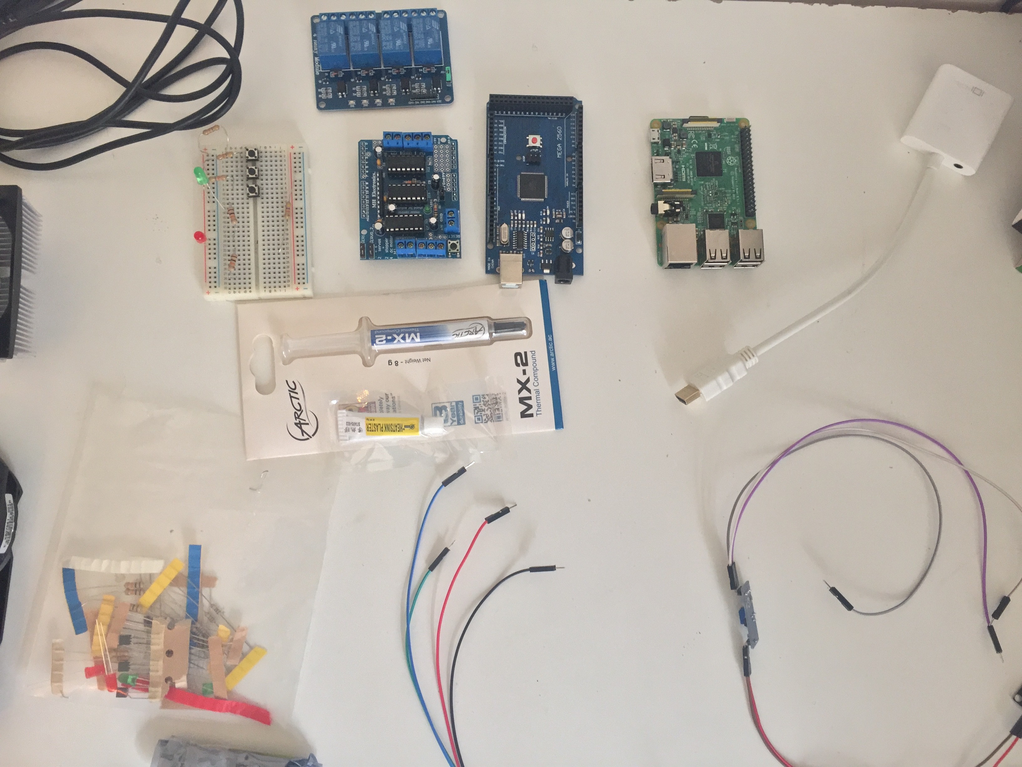
##Arduino and Rpi Boards:
Arduino Mega Clone (10,55 €)
L293D Arduino Motor Shield(4,04 €)
4x Arduino Relay Board (5,25 €)
Half Size Breadboard (1,34 €)
Heatsink Paste (2 €)
Thermal Paste (Salvage 6 €)
Bunch of resistors, NPN Transistor, LEDs... (Salvage 3 €?)
Also for the interfacing i will use a Rpi Model 3 B with Raspbian (Optional 44 €)
For which i needed to buy:
16 Gb MicroSD (Optional 7 €)
HDMI to VGA (Optional12 €)
VGA cable (Optional 2 €)
USB Mouse (Optional 8 €)
USB Keyboard (Optional 2 €)
VGA Monitor (Optional 15 € Bargain)
Hot glue gun (Optional 3 € with glue Bargain)
![]()
##
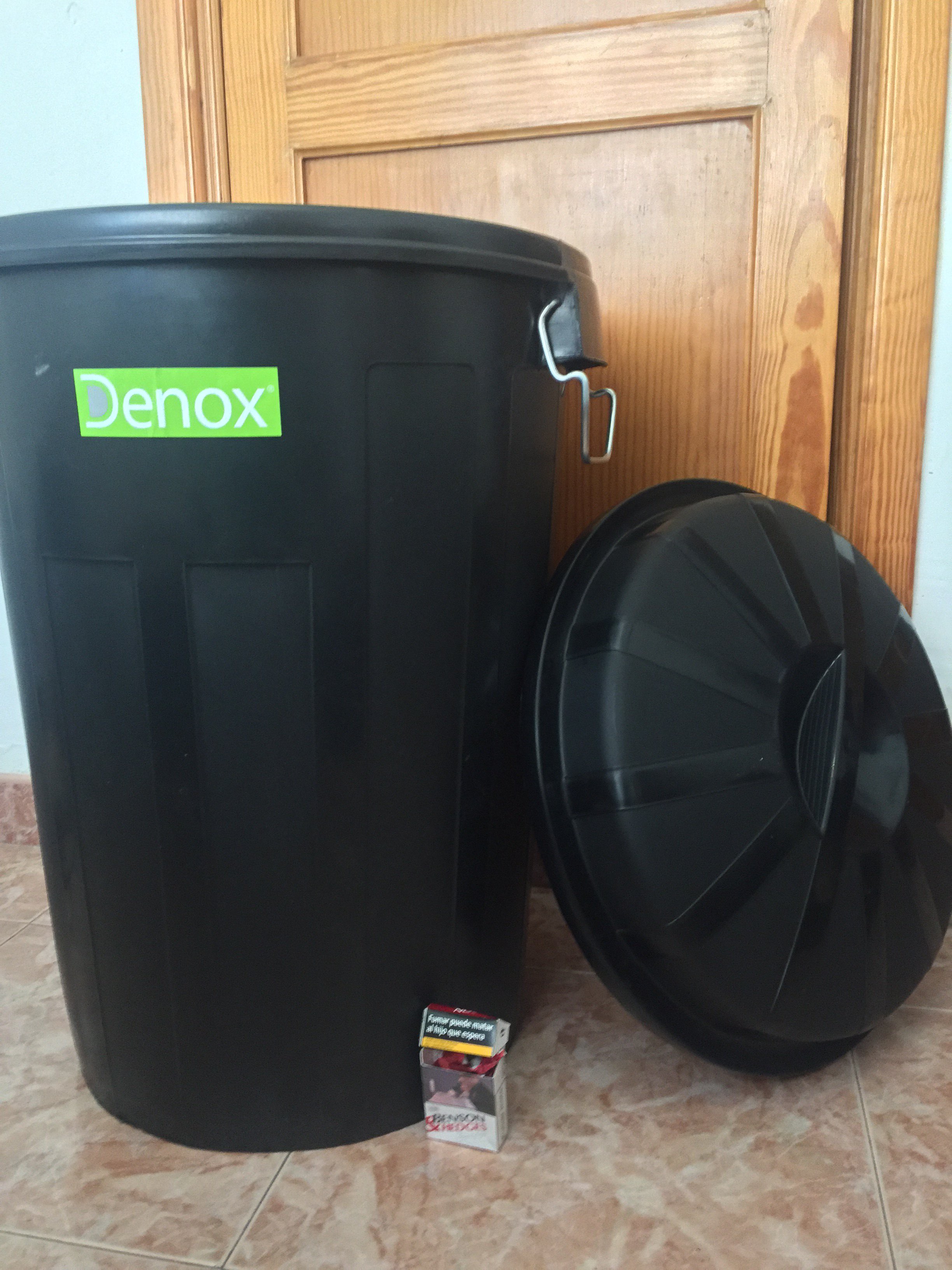
90 L Container (18 €)
7l Soil Container and Soil (3,50 €)
![]()
##Still needed
Copper and copper melterer (Optional 5 €, Arrives Monday)
Some aluminium where put the leds
Aluminium for Reflecting light
##Total:
With Salvage price and withouth optional things : 160,93 €
Salvage makes me save (in my case): 42,05 €
Total project cost (discounting salvage): 118,88 €
LED Lights and drivers: 56,89 €
Total Project cost without light: 61,99 €
Rpi with Monitor etc: 90 € (not only for this)
Book + Optional Tools: 32 €
Total Price of everithing involved with salvage price discounted: 240,88 €
Electrical pieces, arduinos, sensors, and shields were bought on ebay and the local shop, LEDs on Amazon.
-
Prototyping the conections
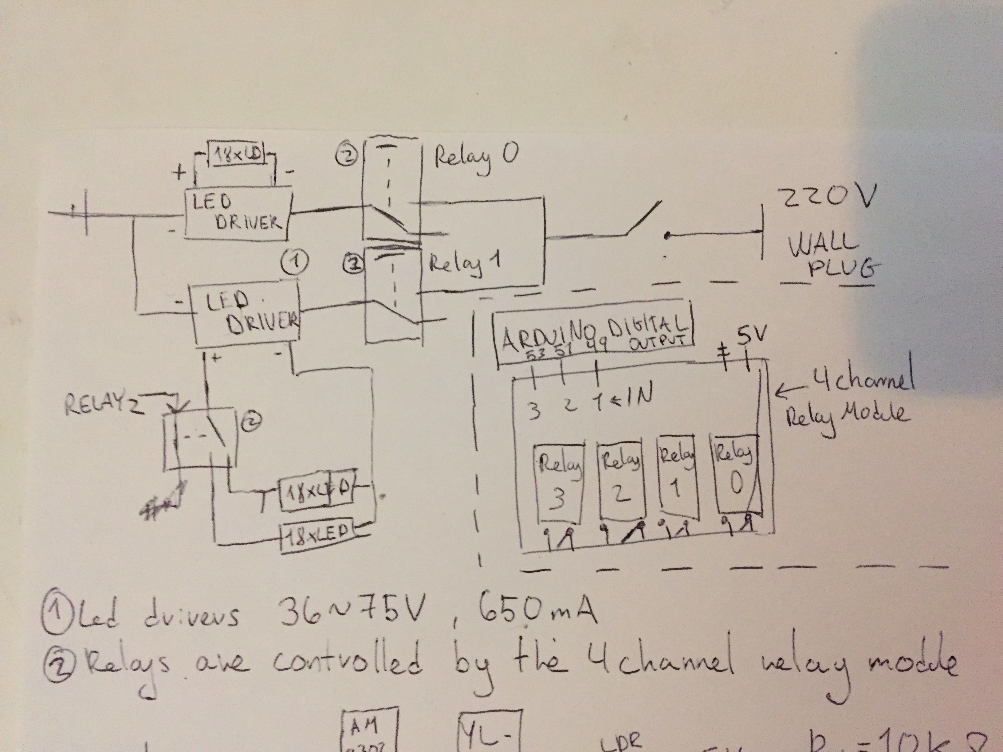
01/08/2017 at 12:53 • 0 commentsFor the start of this project i have been working on the wiring of what will be the first prototype. It will be a 10 gal bucket with the 3 18x led arrays connected at the top (red) with their 2x fans and heatsink to cool (white) and with 2x 12V fans at top(purple) and 2x at bottom(green) for climate control, to try to achieve the first goals of the project.
*Thanks to spacebucket community for creating the spacebucket 3d prototyping program, is very helpfull
The design of the wiring sketch is still not definitive as some questions regarding the wiring are still to be resolved, expecially the protection about high voltage management, sith some fuses maybe needed for general protection and about the wiring of the sensors and the fans and the electrical noise that this could provocate.
But is a first aproach
![]()
![]()
![]()
![]()
APBucket (Arduino Plant Bucket)
Indoor plant enviroment measure and control with arduino and Rpi
 ##Led Drivers and 3W leds: