 Alex
Alex-
First assembly test
11/05/2023 at 22:30 • 0 commentsNot yet finished...but every thing fits mechanically. The empty prototype board is for the level shifting. You can also see the Eurorack Power connector on that. The Blue Module is al little LM317 LDO which will probably use to generate some supply voltage for the Badge. The Badge than gets powered via the SAO Header on the front. See also the red and brown cable on the images.
![]()
![]()
-
Basic Idea an some CAD
11/05/2023 at 18:14 • 0 commentsThe badge does have two inputs and two outputs, which can be seen as 0-3V Audio. So convert this to some more Eurorack compatible Levels (still not sure what are the right levels) and make them available on some 3.5mm audio jacks. Than you need some cariiere to mount the Badge in your rack. This is what I cam up with:
Front view of Carrier with four audio Jacks mounting for the badge. And a extended USB for update an other stuff. The USB extender is planed to be this: https://www.adafruit.com/product/3258
On the back: Space for all the needed cables, some LDO module (front blue one) and a prototype PCB. On the Prototype PCB will be space for the eurorack power connector and some circuits for the level adjustment. The Badge will get powered via the LDO form the eurorack power. To connect the Power the SAO-Header on the Top will get used. The goal is not so change or solder anything to the badge itself.
-
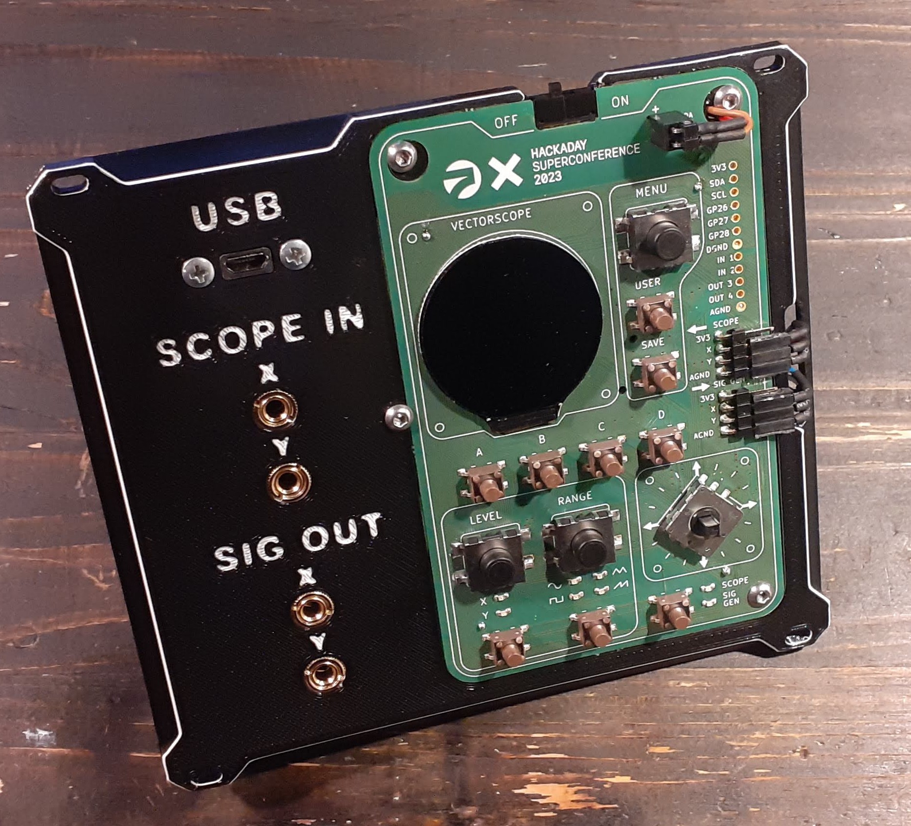
First a Badge is needed
11/05/2023 at 18:03 • 0 commentsAs I am not attending this year's Supercon, I build my own badge. Boardfiles and BOM are available on this github: https://github.com/Hack-a-Day/Vectorscope and with some help of @davedarko I got my rebuild sourced, assembled and running.
![]()
Badge to Eurorack
Frame/Adapter to make the Supercon 2023 Badge Eurorack compatible

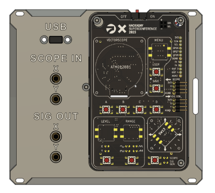 Front view of Carrier with four audio Jacks mounting for the badge. And a extended USB for update an other stuff. The USB extender is planed to be this:
 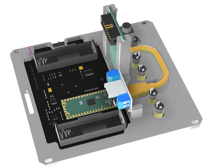 On the back: Space for all the needed cables, some LDO module (front blue one) and a prototype PCB. On the Prototype PCB will be space for the eurorack power connector and some circuits for the level adjustment. The Badge will get powered via the LDO form the eurorack power. To connect the Power the SAO-Header on the Top will get used. The goal is not so change or solder anything to the badge itself.